Anmelden
Hochladen
Anleitungen
Marken
Bosch Anleitungen
Steuergeräte
Rexroth PRC 7000
Bosch Rexroth PRC 7000 Handbücher
Anleitungen und Benutzerhandbücher für Bosch Rexroth PRC 7000. Wir haben
5
Bosch Rexroth PRC 7000 Anleitungen zum kostenlosen PDF-Download zur Verfügung: Betriebsanleitung, Anwendungsbeschreibung
Bosch Rexroth PRC 7000 Betriebsanleitung (334 Seiten)
Schweißsteuerung
Marke:
Bosch
| Kategorie:
Steuergeräte
| Dateigröße: 1.63 MB
Inhaltsverzeichnis
Deutsch
3
Inhaltsverzeichnis
3
1 Zu dieser Dokumentation
7
Gültigkeit der Dokumentation
7
Zusätzliche Dokumentationen
7
Tab. 1: Erforderliche (D) und Ergänzende Unterlagen
7
Darstellung von Informationen
9
Sicherheitshinweise
9
Tab. 2: Beispiel zum Aufbau eines Sicherheitshinweises
9
Tab. 3: Gefahrenklassen nach ANSI Z535
10
Tab. 4: Beispiele zur Klassifikation der Sicherheitshinweise
10
Symbole
11
Bezeichnungen
11
Abkürzungen
11
Tab. 5: Verwendete Symbolik
11
Tab. 6: Bezeichnungen
11
2 Sicherheitshinweise
13
Zu diesem Kapitel
13
Bestimmungsgemäße Verwendung
13
Nicht Bestimmungsgemäße Verwendung
13
Qualifikation des Personals
14
Allgemeine Sicherheitshinweise
16
Produkt- und Technologieabhängige Sicherheitshinweise
17
Evtl. Verwendete Symbolik am Produkt
17
Transport
17
Tab. 7: Mögliche Symbole am Produkt
17
Einbau und Montage
18
Elektrischer Anschluss
20
Betrieb des Produktes
22
Nachrüstungen und Veränderungen durch den Betreiber
24
Wartung und Reparatur
25
Pflichten des Betreibers
27
3 Allgemeine Hinweise zu Sach- und Produktschäden
29
Transport und Lagerung
29
Einbau und Montage
30
Elektrischer Anschluss
32
Betrieb
34
Wartung und Reparatur
35
4 Lieferumfang
37
5 Zu diesem Produkt
39
Tab. 8: Überblick über die Leistungsteiltypen
39
Leistungsbeschreibung
41
Produktbeschreibung
44
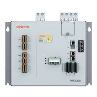
Abb. 1: Schweißsteuerung PRC7000 Frontansicht
44
Abb. 2: Schweißsteuerung PRC7000 Ansicht von Oben
45
Programmierung und Bedienung
46
Funktionsprinzip des Mittelfrequenzschweißens
47
Abb. 3: Übersichts-Blockschaltbild: PRC7000 mit Trafo
47
Abb. 4: Detail-Blockschaltbild der Schweißsteuerungsanlage
47
Abb. 5: Sekundärseitige Gleichrichtung durch den PSG-Transformator
48
Abb. 6: Zusammenhang: Pulsbreite der Primärspannung und Sekundärstrom Beim Mittelfrequenzschweißen
48
Aufbau
49
Abb. 7: Prinzipieller Aufbau einer MF-Schweißeinrichtung mit PRC7000
50
PRC7000 Schnittstellen Übersicht
52
Abb. 8: Schnittstellen PRC7000
52
XDS1 24V Spannungsversorgung, Stoppkreis, Externer Lüfter, HSA
53
Tab. 9: Anschluss, Anschließbare Leiter
53
Abb. 9: SXDS1 Stecker für Versorgung 14 Polig, 2 Reihig
53
XGM1 Trafo Interface (Sekundärstrom, Sekundärspannung, Trafo-Temperatur)
54
Tab. 10: Belegung XDS1 Stecker 14 Polig
54
Abb. 10: XGM1 Stecker für Trafo-Signale 12 Polig, 2 Reihig
54
Tab. 11: Belegung XGM1 Stecker 12 Polig
55
XGM2 Druck Interface
56
Tab. 12: Belegung XGM2 Stecker 8 Polig
56
Abb. 11: XGM2 Stecker für Druck-Signale 8 Polig, 2 Reihig
56
XGM3 Kraft Interface
57
Tab. 13: Belegung XGM3 Stecker 10 Polig
57
Abb. 12: XGM3 Stecker 10 Polig, 2 Reihig
57
XGM4 Analoges Interface, High Speed- Eingänge
58
Tab. 14: Belegung XGM4 Stecker 16 Polig
58
Abb. 13: XGM4 Stecker 16 Polig, 2 Reihig
58
XGD1, XGD2, XGD3 Diskrete Ein/Ausgänge
59
Tab. 15: Anschluss, Anschließbare Leiter
59
Tab. 16: XGD1 Stecker für Diskrete 24V Eingänge E00 bis E07
60
Tab. 17: XGD2 Stecker für Diskrete 24V Eingänge E08 bis E15
61
Tab. 18: XGD3 Stecker für Diskrete 24V Ausgänge A00 bis A07
62
Tab. 19: Technische Daten: Ein/Ausgänge
63
XGSD1 Steckverbinder SD-Karte
64
Abb. 14: Steckverbinder XGSD1
64
XFE0 Ethernet Port 0, Bedienoberfläche
65
Abb. 15: Steckverbinder XFE0 Ethernet Port 0
65
XFS1 WIC (Weld Interface Controller) Port 1
66
Abb. 16: Steckverbinder XFS1 WIC Port 1
66
XFS2 WIC (Weld Interface Controller) Port 2
67
Abb. 17: Steckverbinder XFS2 WIC Port 2
67
XFU0 USB Port 0
68
Abb. 18: Steckverbinder XFU0 USB Port 0
68
XFU1 USB Port 1
69
Abb. 19: Steckverbinder XFU1 USB Port 1
69
Leds
70
Tab. 20: LED CU „Status Control Unit
70
Tab. 21: LED PU „Status Power Unit
70
Tab. 22: LED STZ „Stromzeit
70
Module
71
Anybus-Modul "Profinet IO
71
Abb. 20: Anybus-Modul "Profinet IO" (2-Port-Variante)
71
Anybus-Modul "CC Ethernet 100 Mbit
72
Abb. 21: Anybus-Modul "CC Ethernet 100 Mbit" (1-Port-Variante)
72
Diagnosemodul
73
Abb. 22: Frontansicht Diagnosemodul
73
Abb. 23: Diagnosemodul: Hauptmenü
74
Abb. 24: Diagnosemodul: Menü Network
75
UI-Regler-Funktionalität
76
Belastung und Dimensionierung
77
Grundlegendes
77
Wird der Umrichter Überlastet
77
Belastungsdiagramme
79
Abb. 25: Zulässiger Primärstrom in Abhängigkeit der ED: PRC 7300 L1/W1
79
Abb. 26: Zulässiger Primärstrom in Abhängigkeit der ED: PRC 7300 L2/W2
80
Abb. 27: Zulässiger Primärstrom in Abhängigkeit der ED: PRC 7400 L1/W1
81
Abb. 28: Zulässiger Primärstrom in Abhängigkeit der ED: PRC 7400 L2/W2
82
Abb. 29: Typenschlüssel der PRC7000-Baureihe
82
6 Transport und Lagerung
85
7 Montage
87
Produkt Montieren
87
Maßbilder und Anschlusspositionen
88
Abb. 30: Maßbild PRC 7300 L/W Vorderansicht Frontseite
88
Abb. 31: Maßbild PRC7300 L Seitenansicht
89
Abb. 32: Maßbild PRC7300 W Seitenansicht
90
Abb. 33: Maßbild PRC7300 L Ansicht von Oben
91
Abb. 34: Maßbild PRC7300 W Ansicht von Oben
92
Abb. 35: Maßbild PRC7300 L Ansicht von Unten
93
Abb. 36: Maßbild PRC7300 W Ansicht von Unten
94
Abb. 37: Maßbild PRC7300 L Ansicht von Hinten
95
Abb. 38: Maßbild PRC7300 W Ansicht von Hinten
96
Abb. 39: Bohrbild PRC7300 L/W
97
Abb. 40: Maßbild PRC 7400 L/W Vorderansicht Frontseite
98
Abb. 41: Maßbild PRC7400 L Seitenansicht
99
Abb. 42: Maßbild PRC7400 W Seitenansicht
100
Abb. 43: Maßbild PRC7400 L Ansicht von Oben
101
Abb. 44: Maßbild PRC7400 W Ansicht von Oben
101
Abb. 45: Maßbild PRC7400 L Ansicht von Unten
102
Abb. 46: Maßbild PRC7400 W Ansicht von Unten
102
Abb. 47: Maßbild PRC7400 L Ansicht von Hinten
103
Abb. 48: Maßbild PRC7400 W Ansicht von Hinten
104
Produkt Elektrisch Anschließen
105
Entstörung
105
Abb. 49: Entstörbeispiele
105
Netzanschluss
106
Tab. 23: Dimensionierung Entstörkomponenten
106
Abb. 50: Typischer Verlauf der Netzspannung (Oben) und des Dazugehörigen Netzstro
106
Trafoanschluss (Primärkreis)
108
Anschluss Programmiergerät
108
24VDC-Logikversorgung (XDS1, Eingang)
109
Externer Lüfter (XDS1, Ausgang)
110
Analoge Ausgabe der Elektrodenkraft (XGM3, Ausgang)
111
Rückmeldung Elektrodenkraft
112
Sekundärstrom-Messeingang (XGM1)
114
Überwachung Transformator-Temperatur (XGM1)
116
Sekundärspannungs-Messeingang (XGM1)
117
Hauptschalter-Auslösung (XDS1)
118
Wasserversorgung Anschließen
119
8 Inbetriebnahme
121
9 Betrieb
125
10 Instandhaltung und -Setzung
127
Wartungsplan
127
Wartung
128
Austausch von Komponenten (Servicekonzept)
129
Sicherung Bzw. Nachladen von Firmware vor Ort
129
Austausch in Ausnahmefällen
129
Firmware-Aktualisierung
130
Ersatzteile
131
Tab. 24: Ersatzteile
131
11 Demontage und Austausch
133
12 Entsorgung
135
Umweltschutz
135
13 Erweiterung und Umbau
137
Optionales Zubehör
137
Tab. 25: Optionales Zubehör
137
14 Fehlersuche und -Behebung
139
15 Technische Daten
141
Tab. 26: Leistungsteil-Übergreifende Allgemeine Daten
141
Tab. 27: Leistungsteil-Übergreifende Umgebungsbezogene Daten
142
Tab. 28: Leistungsteil-Übergreifende Elektrische Daten
143
Tab. 29: PRC7300 - Mechanische Daten
144
Tab. 30: PRC7300 - Umgebungsbezogene Daten
144
Tab. 31: PRC7300 - Elektrische Daten
144
Tab. 32: PRC7400 - Mechanische Daten
145
Tab. 33: PRC7400 - Umgebungsbezogene Daten
145
Tab. 34: PRC7400 - Elektrische Daten
145
16 Open Source Software in der PRC7000
147
17 Tabellenverzeichnis
159
18 Abbildungsverzeichnis
161
19 Abkürzungen
163
Tab. 35: Abkürzungen und Begriffserklärungen
163
20 Stichwortverzeichnis
167
English
170
1 Regarding this Documentation
173
Validity of the Documentation
173
Additional Documentation
173
Table 1: Necessary (D) and Supplementary Documents
173
Presentation of Information
174
Safety Instructions
174
Table 2: Example for the Structure of a Safety Instruction
174
Table 3: Danger Classes According to ANSI Z535
175
Table 4: Examples for Classification of Safety Instructions
175
Icons
176
Designations
176
Abbreviations
176
Table 5: Icons Used
176
Table 6: Designations
176
2 Safety Instructions
177
On this Section
177
Intended Use
177
Inappropriate Use
177
Qualification of Personnel
178
General Safety Instructions
180
Product- and Technology-Dependent Safety Instructions
181
Possible Icons on the Product
181
Transport
181
Table 7: Possible Icons on the Product
181
Installation and Assembly
182
Electrical Connection
184
Operating the Product
186
Retrofits and Modifications by the Operator
188
Maintenance and Repair
189
Obligations of the Operator
191
3 General Notes Regarding Damage to Property and Products
193
Transport and Storage
193
Installation and Assembly
194
Electrical Connection
196
Operation
198
Maintenance and Repair
199
4 Scope of Delivery
201
5 Information on this Product
203
Table 8: Overview of the Types of Power Units
203
Description of Performance
205
Product Description
208
Fig. 1:Weld Timer PRC7000 Front View
208
Fig. 2:Weld Timer PRC7000 Top View
209
Programming and Operation
210
Functional Principle of Medium-Frequency Welding
211
Fig. 3:Block Diagram Overview: PRC7000 with Transformer
211
Fig. 4:Detailed Block Diagram of a Welding System with PRC7000
211
Fig. 5:Secondary Rectification by the PSG Transformer
212
Fig. 6:Interrelationship: Pulse Width of Primary Voltage and Secondary Current with Medium-Frequency Welding
212
Structure
213
Fig. 7:General Structure of an MF Welding System with PRC7000
214
PRC7000 Interfaces Overview
216
Fig. 8:PRC7000 Interfaces
216
XDS1 Connector 24V Voltage Supply, Stop Circuit, Ext. Fan, HSA (Main Switch Release)
217
Table 9: Conductors Suitable for Connection
217
Fig. 9:XDS1 Plug for Supply 14-Pole, 2-Row
217
Table 10: Allocation XDS1 Plug 14-Pole
218
XGM1 Transformer Interface (Secondary Current, Secondary Voltage, Transformer Temperature)
219
Table 11: Allocation XGM1 Plug 12-Pole
219
Fig. 10: XGM1 Plug for Transformer Signals 12-Pole, 2-Row
219
XGM2 Pressure Interface
220
Table 12: Allocation XGM2 Connector 8-Pole
220
Fig. 11: XGM2 Plug for Pressure-Signals 8-Pole, 2-Row
220
XGM3 Force Interface
221
Table 13: Allocation XGM3 Plug 10-Pole
221
Fig. 12: XGM3 Plug for Pressure Signals 8-Pole, 2-Row
221
XGM4 Analog Interface, High Speed Inputs
222
Table 14: Allocation XGM4 Plug 16-Pole
222
Fig. 13: XGM4 Plug 16-Pole, 2-Row
222
XGD1, XGD2, XGD3 Discrete Inputs/Outputs
223
Table 15: Conductors Suitable for Connection
223
Table 16: XGD1 Plug for Discrete 24V Inputs I00 to I07
224
Table 17: XGD2 Plug for Discrete 24V Inputs I08 to I15
225
Table 18: XGD3 Plug for Discrete 24V Outputs O00 to O07
226
Table 19: Technical Data: Inputs/Outputs
227
XGSD1 Connector SD Card
228
Fig. 14: Connector XGSD1
228
XFE0 Ethernet Port 0, User Interface
229
Fig. 15: Connector XFE0 Ethernet Port 0
229
XFS1 WIC (Weld Interface Controller) Port 1
230
Fig. 16: Connector XFS1 WIC Port 1
230
XFS2 WIC (Weld Interface Controller) Port 2
231
Fig. 17: Connector XFS2 WIC Port 2
231
XFU0 USB Port 0
232
Fig. 18: Connector XFU0 USB Port 0
232
XFU1 USB Port 1
233
Fig. 19: Connector XFU1 USB Port 1
233
Leds
234
Table 20: CU „Status Control Unit" LED
234
Table 21: PU „Status Power Unit" LED
234
Table 22: STZ „Weld Time" LED
234
Modules
235
Anybus Module "Profinet IO
235
Fig. 20: Anybus Module "Profinet IO" (2-Port Variant)
235
Anybus Module "CC Ethernet 100 Mbit
237
Fig. 21: Anybus Module "CC Ethernet 100 Mbit" (1-Port-Variant)
237
Diagnosis Module
238
Fig. 22: Diagnosis Module: Front Panel View
238
Fig. 23: Diagnosis Module: Main Menu
239
Fig. 24: Diagnosis Module: Network Menu
240
UI-Controller Functionality
241
Load and Rating
242
Basics
242
Is the Inverter Overloaded
242
Load Diagrams
244
Fig. 25: Permitted Primary Current Depending on the Duty Cycle: PRC7300 L1/W1
244
Fig. 26: Permitted Primary Current Depending on the Duty Cycle: PRC7300 L2/W2
245
Fig. 27: Permitted Primary Current Depending on the Duty Cycle: PRC7400 L1/W1
246
Fig. 28: Permitted Primary Current Depending on the Duty Cycle: PRC7400 L2/W2
247
6 Transport and Storage
249
7 Assembly
251
Assembling the Product
251
Dimensioned Drawings and Locations of Connections
251
Fig. 29: Dimensioned Drawing PRC7300 L/W Front View
251
Fig. 30: Dimensioned Drawing PRC7300 L Side View
252
Fig. 31: Dimensioned Drawing PRC7300 W Side View
253
Fig. 32: Dimensioned Drawing PRC7300 L Top View
254
Fig. 33: Dimensioned Drawing PRC7300 W Top View
255
Fig. 34: Dimensioned Drawing PRC7300 L Bottom View
256
Fig. 35: Dimensioned Drawing PRC7300 W Bottom View
257
Fig. 36: Drawing PRC7300 L View from Behind
258
Fig. 37: Drawing PRC7300 W View from Behind
259
Fig. 38: Drilling Pattern PRC7300 L/W
260
Fig. 39: Dimensioned Drawing PRC 7400 L/W Front View
261
Fig. 40: Dimensioned Drawing PRC7400 L Side View
262
Fig. 41: Dimensioned Drawing PRC7400 W Side View
263
Fig. 42: Drawing PRC7400 L Top View
264
Fig. 43: Drawing PRC7400 W Top View
264
Fig. 44: Dimensioned Drawing PRC7400 L Bottom View
265
Fig. 45: Dimensioned Drawing PRC7400 W Bottom View
265
Fig. 46: Drawing PRC7400 L View from Behind
266
Fig. 47: Drawing PRC7400 W View from Behind
267
Electrical Connection of the Product
269
Interference Suppression
269
Fig. 48: Noise Suppression Examples
269
Line Connection
270
Table 23: Rating of Noise Suppression Equipment
270
Fig. 49: Typical Curve of the Mains Voltage (Top) and the Related Mains Current (Bottom) in One Phase During the Welding Process
270
Transformer Connection (Primary Circuit)
272
Connection for Programming Terminal
272
24VDC Logic Supply (XDS1, Input)
273
Fig. 50: Logic Supply Input of the Timer
273
External Fan (XDS1, Output)
274
Analog Output of the Electrode Force (XGM3, Output)
275
Electrode Force Feedback
276
Input for Secondary Current Measurement (XGM1)
278
Transformer Temperature Monitoring (XGM1)
280
Measuring Input for Secondary Voltage Measurement (XGM1)
281
Main Switch Tripped (XDS1)
282
Connecting the Water Supply
283
8 Commissioning
285
9 Operation
289
10 Service and Repair
291
Maintenance Schedule
291
Maintenance
292
Replacement of Components (Service Concept)
293
Save and Load of Firmware on Location
293
Replacement in Special Cases
293
Firmware Update
294
Spare Parts
295
Table 24: Spare Parts
295
11 Dismantling and Replacement
297
12 Disposal
299
Environmental Protection
299
13 Extension and Conversion
301
Optional Accessories
301
Table 25: Optional Accessories
301
14 Troubleshooting
303
15 Technical Data
305
Table 26: General Data Across Power Units
305
Table 27: Environmental Data Across Power Units
306
Table 28: Electrical Data Across Power Units
307
Table 29: PRC7300 - Mechanical Data
308
Table 30: PRC7300 - Environmental Data
308
Table 31: PRC7300 - Electrical Data
308
Table 32: PRC7400 - Mechanical Data
309
Table 33: PRC7400 - Environmental Data
309
Table 34: PRC7400 - Electrical Data
310
16 Open Source Software in PRC7000
311
17 List of Tables
323
18 List of Figures
325
19 Abbreviations
327
Table 35: Abbreviations and Definitions
327
20 Index
331
Werbung
Bosch Rexroth PRC 7000 Betriebsanleitung (256 Seiten)
Marke:
Bosch
| Kategorie:
Schweißgeräte
| Dateigröße: 1.12 MB
Inhaltsverzeichnis
Deutsch
3
Inhaltsverzeichnis
3
Notizen | Notes
6
1 Zu dieser Dokumentation
7
Gültigkeit der Dokumentation
7
Zusätzliche Dokumentationen
7
Tab. 1: Erforderliche (D) und Ergänzende Unterlagen
7
Darstellung von Informationen
8
Sicherheitshinweise
8
Tab. 2: Beispiel zum Aufbau eines Sicherheitshinweises
8
Tab. 3: Gefahrenklassen nach ANSI Z535
9
Tab. 4: Beispiele zur Klassifikation der Sicherheitshinweise
9
Symbole
10
Bezeichnungen
10
Abkürzungen
10
Tab. 5: Verwendete Symbolik
10
Tab. 6: Bezeichnungen
10
2 Sicherheitshinweise
11
Zu diesem Kapitel
11
Bestimmungsgemäße Verwendung
11
Nicht Bestimmungsgemäße Verwendung
11
Qualifikation des Personals
12
Allgemeine Sicherheitshinweise
14
Produkt- und Technologieabhängige Sicherheitshinweise
15
Evtl. Verwendete Symbolik am Produkt
15
Transport
15
Einbau und Montage
15
Tab. 7: Mögliche Symbole am Produkt
15
Elektrischer Anschluss
17
Betrieb des Produktes
19
Nachrüstungen und Veränderungen durch den Betreiber
20
Wartung und Reparatur
20
Pflichten des Betreibers
21
3 Allgemeine Hinweise zu Sach- und Produktschäden
23
Transport und Lagerung
23
Einbau und Montage
24
Elektrischer Anschluss
25
Betrieb
27
Wartung und Reparatur
27
4 Lieferumfang
29
5 Zu diesem Produkt
31
Tab. 8: Überblick der Simulierten Steuerungstypen
31
Leistungsbeschreibung
33
Produktbeschreibung
36
Abb. 1: Simulator PRC7000 Frontansicht
36
Abb. 2: Simulator PRC7000 Seitenansicht Beschriftung
37
Programmierung und Bedienung
38
Aufbau
39
Simulator PRC7000 Schnittstellen Übersicht
40
Abb. 3: Schnittstellen Simulator PRC7000
40
XDS1 24V Spannungsversorgung, Stoppkreis, Externer Lüfter, HSA
41
Tab. 9: Anschluss, Anschließbare Leiter
41
Abb. 4: XDS1 Stecker für Versorgung 14 Polig, 2 Reihig
41
Tab. 10: Belegung XDS1 Stecker 14 Polig
42
XGM1 Trafo Interface (Sekundärstrom, Sekundärspannung, Trafo-Temperatur)
43
Tab. 11: Belegung XGM1 Stecker 12 Polig
43
Abb. 5: XGM1 Stecker für Trafo-Signale 12 Polig, 2 Reihig
43
XGM2 Druck Interface
44
Tab. 12: Belegung XGM2 Stecker 8 Polig
44
Abb. 6: XGM2 Stecker für Druck-Signale 8 Polig, 2 Reihig
44
XGM3 Kraft Interface
45
Tab. 13: Belegung XGM3 Stecker 10 Polig
45
Abb. 7: XGM3 Stecker 10 Polig, 2 Reihig
45
XGM4 Analoges Interface, High Speed- Eingänge
46
Tab. 14: Belegung XGM4 Stecker 16 Polig
46
Abb. 8: XGM4 Stecker 16 Polig, 2 Reihig
46
XGD1, XGD2, XGD3 Diskrete Ein/Ausgänge
47
Tab. 15: Anschluss, Anschließbare Leiter
47
Tab. 16: XGD1 Stecker für Diskrete 24V Eingänge E00 bis E07
48
Tab. 17: XGD2 Stecker für Diskrete 24V Eingänge E08 bis E15
49
Tab. 18: XGD3 Stecker für Diskrete 24V Ausgänge A00 bis A07
50
Tab. 19: Technische Daten: Ein/Ausgänge
51
XGSD1 Steckverbinder SD-Karte
52
Abb. 9: Steckverbinder XGSD1
52
XFE0 Ethernet Port 0, Bedienoberfläche
53
Abb. 10: Steckverbinder XFE0 Ethernet Port 0
53
XFS1 WIC (Weld Interface Controller) Port 1
54
Abb. 11: Steckverbinder XFS1 WIC Port 1
54
XFS2 WIC (Weld Interface Controller) Port 2
55
Abb. 12: Steckverbinder XFS2 WIC Port 2
55
XFU0 USB Port 0
56
Abb. 13: Steckverbinder XFU0 USB Port 0
56
XFU1 USB Port 1
57
Abb. 14: Steckverbinder XFU1 USB Port 1
57
Leds
58
Tab. 20: LED CU „Status Control Unit
58
Tab. 21: LED PU „Status Power Unit
58
Tab. 22: LED STZ „Stromzeit
58
Module
59
Anybus-Modul "Profinet IO
59
Abb. 15: Anybus-Modul "Profinet IO" (2-Port-Variante)
59
Anybus-Modul "CC Ethernet 100 Mbit
60
Abb. 16: Anybus-Modul "CC Ethernet 100 Mbit" (1-Port-Variante)
60
Diagnosemodul
61
Abb. 17: Frontansicht Diagnosemodul
61
Abb. 18: Diagnosemodul: Hauptmenü
62
Abb. 19: Diagnosemodul: Menü Network
63
UI-Regler-Funktionalität
65
Belastung und Dimensionierung
66
Grundlegendes
66
6 Transport und Lagerung
69
7 Montage
71
Produkt Montieren
71
Maßbilder und Anschlusspositionen
72
Abb. 20: Maßbild Simulator PRC7000 Vorderansicht Frontseite
72
Abb. 21: Maßbild Simulator PRC7000 Ansicht von Oben
73
Produkt Elektrisch Anschließen
74
Entstörung
74
Abb. 22: Entstörbeispiele
74
Anschluss Programmiergerät
75
Tab. 23: Dimensionierung Entstörkomponenten
75
VDC-Logikversorgung (XDS1, Eingang)
76
Abb. 23: Logikversorgungseingang der Steuerung
76
Externer Lüfter (XDS1, Ausgang)
77
Abb. 24: Anschluss eines Externen Lüftermoduls
77
Analoge Ausgabe der Elektrodenkraft (XGM3, Ausgang)
78
Abb. 25: Analoge Ausgabe der Kraftstellgröße
78
Rückmeldung Elektrodenkraft
79
Abb. 26: Mögliche Rückmeldeeingänge für Druck/Kraft
80
Sekundärstrom-Messeingang (XGM1)
81
Abb. 27: Anschluss eines Sekundärseitigen KSR-Sensors
81
Überwachung Transformator-Temperatur (XGM1)
83
Abb. 28: Anschluss zur Überwachung der Schweißtrafo-Temperatur
83
Abb. 29: keine Überwachung der Trafo-Temperatur durch die Steuerung
83
Sekundärspannungs-Messeingang (XGM1)
84
Abb. 30: bei Simulator PRC7000: Anschluss zur Sekundärspannungsmessung
84
8 Inbetriebnahme
85
9 Betrieb
87
10 Instandhaltung und -Setzung
89
Wartungsplan
89
Wartung
90
Austausch von Komponenten (Servicekonzept)
91
Sicherung Bzw. Nachladen von Firmware vor Ort
91
Austausch in Ausnahmefällen
91
Firmware-Aktualisierung
92
Ersatzteile
93
Tab. 24: Ersatzteile
93
11 Demontage und Austausch
95
12 Entsorgung
97
Umweltschutz
97
13 Erweiterung und Umbau
99
14 Fehlersuche und -Behebung
101
15 Technische Daten
103
Tab. 25: Leistungsteil-Übergreifende Allgemeine Daten
103
Tab. 26: Leistungsteil-Übergreifende Umgebungsbezogene Daten
104
Tab. 27: Leistungsteil-Übergreifende Elektrische Daten
105
Tab. 28: Simulator PRC7300 / PRC7400 - Mechanische Daten
106
Tab. 29: Simulator PRC7300 / PRC7400 - Umgebungsbezogene Daten
106
16 Open Source Software IM Simulator PRC7000
107
17 Tabellenverzeichnis
119
18 Abbildungsverzeichnis
121
19 Abkürzungen
123
Tab. 30: Abkürzungen und Begriffserklärungen
123
20 Stichwortverzeichnis
125
English
128
1 Regarding this Documentation
133
Validity of the Documentation
133
Additional Documentation
133
Table 1: Necessary (D) and Supplementary Documents
133
Presentation of Information
134
Safety Instructions
134
Table 2: Example for the Structure of a Safety Instruction
134
Table 3: Danger Classes According to ANSI Z535
135
Table 4: Examples for Classification of Safety Instructions
135
Icons
136
Designations
136
Abbreviations
136
Table 5: Icons Used
136
Table 6: Designations
136
2 Safety Instructions
137
On this Section
137
Intended Use
137
Inappropriate Use
137
Qualification of Personnel
138
General Safety Instructions
140
Product- and Technology-Dependent Safety Instructions
141
Possible Icons on the Product
141
Transport
141
Installation and Assembly
141
Table 7: Possible Icons on the Product
141
Electrical Connection
143
Operating the Product
145
Retrofits and Modifications by the Operator
146
Maintenance and Repair
147
Obligations of the Operator
148
3 General Information on Damage to Property and Products
149
Transport and Storage
149
Installation and Assembly
150
Electrical Connection
151
Operation
152
Maintenance and Repair
152
4 Scope of Delivery
155
5 Information on this Product
157
Table 8: Overview of the Simulated Types of Timers
157
Description of Performance
159
Product Description
162
Fig. 1:Weld Timer Simulator PRC7000 Front View
162
Fig. 2:Simulator PRC7000 Side View
163
Programming and Operation
164
Structure
165
Simulator PRC7000 Interface Overview
166
Fig. 3:Interface Simulator PRC7000
166
XDS1 24V Voltage Supply, Stop Circuit, Ext. Fan, HSA (Main Switch Release)
167
Table 9: Conductors Suitable for Connection
167
Fig. 4:XDS1 Plug for Supply 14-Pole, 2-Row
167
Table 10: Allocation XDS1 Plug 14-Pole
168
XGM1 Transformer Interface (Secondary Current, Secondary Voltage, Transformer Temperature)
169
Table 11: Allocation XGM1 Plug 12-Pole
169
Fig. 5:XGM1 Plug for Transformer Signals 12-Pole, 2-Row
169
XGM2 Pressure Interface
170
Table 12: Allocation XGM2 Plug 8 Pole
170
Fig. 6:XGM2 Connector for Pressure-Signals 8-Pole, 2-Row
170
XGM3 Force Interface
171
Table 13: Allocation XGM3 Plug 10-Pole
171
Fig. 7:XGM3 Plug for Pressure Signals 10-Pole, 2-Row
171
XGM4 Analog Interface, High Speed Inputs
172
Table 14: Allocation XGM4 Connector 16 Pin
172
Fig. 8: XGM4 Plug 16-Pole, 2-Row
172
XGD1, XGD2, XGD3 Discrete Inputs/Outputs
173
Table 15: Conductors Suitable for Connection
173
Table 16: XGD1 Plug for Discrete 24V Inputs I00 to I07
174
Table 17: XGD2 Plug for Discrete 24V Inputs I08 to I15
175
Table 18: XGD3 Plug for Discrete 24V Outputs O00 to O07
176
Table 19: Technical Data: Inputs/Outputs
177
XGSD1 Connector SD Card
178
Fig. 9:Connector XGSD1
178
XFE0 Ethernet Port 0, User Interface
179
Fig. 10: Connector XFE0 Ethernet Port 0
179
XFS1 WIC (Weld Interface Controller) Port 1
180
Fig. 11: Connector XFS1 WIC Port 1
180
XFS2 WIC (Weld Interface Controller) Port 2
181
Fig. 12: Connector XFS2 WIC Port 2
181
XFU0 USB Port 0
182
Fig. 13: Connector XFU0 USB Port 0
182
XFU1 USB Port 1
183
Fig. 14: Connector XFU1 USB Port 1
183
Leds
184
Table 20: CU „Status Control Unit„ LED
184
Table 21: PU „Status Power Unit" LED
184
Table 22: LED STZ „Weld Time
184
Modules
185
Anybus Module "Profinet IO
185
Fig. 15: Anybus Module "Profinet IO" (2-Port Variant)
185
Anybus Module "CC Ethernet 100 Mbit
187
Fig. 16: Anybus Module "CC Ethernet 100 Mbit" (1-Port-Variant)
187
Diagnosis Module
188
Fig. 17: Diagnosis Module: Front Panel View
188
Fig. 18: Diagnosis Module: Main Menu
189
Fig. 19: Diagnosis Module: Network Menu
189
UI-Controller Functionality
191
Load and Rating
192
Basics
192
6 Transport and Storage
195
7 Assembly
197
Assembling the Product
197
Dimensioned Drawings and Locations of Connections
198
Fig. 20: Dimension Drawing Simulator PRC7000 Front View
198
Fig. 21: Dimension Drawing Simulator PRC7000 Top View
199
Electrical Connection of the Product
200
Interference Suppression
200
Table 23: Rating of Noise Suppression Equipment
200
Fig. 22: Noise Suppression Examples
200
Connection for Programming Terminal
201
VDC Logic Supply (XDS1, Input)
202
Fig. 23: Logic Supply Input of the Timer
202
External Fan (XDS1, Output)
203
Fig. 24: Connecting an External Fan Module
203
Analog Output of the Electrode Force (XGM3, Output)
204
Fig. 25: Analog Output of the Force Actuating Variable
204
Electrode Force Feedback
205
Fig. 26: Possibly Available Feedback Signal Inputs for Pressure/Force
206
Input for Secondary Current Measurement (XGM1)
207
Fig. 27: Connecting a KSR Sensor on the Secondary Side
207
Transformer Temperature Monitoring (XGM1)
209
Fig. 28: Connection for Monitoring the Welding Transformer Temperature
209
Fig. 29: Transformer Temperature Not Monitored by Timer
209
Measuring Input for Secondary Voltage Measurement (XGM1)
210
Fig. 30: with Simulator PRC7000: Connection for Secondary Voltage Measurement
210
8 Commissioning
211
9 Operation
213
10 Service and Repair
215
Maintenance Schedule
215
Maintenance
216
Replacement of Components (Service Concept)
217
Save and Load of Firmware in Field
217
Replacement in Special Cases
217
Firmware Update
218
Spare Parts
219
Table 24: Spare Parts
219
11 Dismantling and Replacement
221
12 Disposal
223
Environmental Protection
223
13 Extension and Conversion
225
14 Troubleshooting
227
15 Technical Data
229
Table 25: General Data Across Power Units
229
Table 26: Environmental Data Across Power Units
230
Table 27: Electrical Data Across Power Units
231
Table 28: Simulator PRC7300 / 7400 - Mechanical Data
231
Table 29: Simulator PRC7300 / 7400 - Environmental Data
231
16 Open Source Software in Simulator PRC7000
233
17 List of Tables
245
18 List of Figures
247
19 Abbreviations
249
Table 30: Abbreviations and Definitions
249
20 Index
253
Bosch Rexroth PRC 7000 Betriebsanleitung (118 Seiten)
Marke:
Bosch
| Kategorie:
Module
| Dateigröße: 3.78 MB
Inhaltsverzeichnis
Deutsch
3
Inhaltsverzeichnis
3
1 Zu dieser Dokumentation
6
Gültigkeit der Dokumentation
6
Erforderliche und Ergänzende Dokumentationen
6
Darstellung von Informationen
7
Sicherheitshinweise
7
Symbole
9
Bezeichnungen
9
Abkürzungen
10
2 Sicherheitshinweise
10
Zu diesem Kapitel
10
Bestimmungsgemäße Verwendung
10
Nicht Bestimmungsgemäße Verwendung
11
Qualifikation des Personals
11
Allgemein Sicherheitshinweise
12
Produkt- und Technologieabhängige Sicherheitshinweise
13
Evtl. Verwendete Symbolik am Produkt
13
Transport
14
Einbau und Montage
14
Elektrischer Anschluss
15
Betrieb des Produktes
16
Nachrüstungen und Veränderungen durch den Betreiber
16
Wartung und Reparatur
17
Pflichten des Betreibers
17
3 Allgemeine Hinweise vor Sachschäden und Produktschäden
18
Transport und Lagerung
18
Einbau und Montage
18
Elektrischer Anschluss
19
Betrieb
20
Wartung und Reparatur
21
4 Lieferumfang
21
5 Zu diesem Produkt
22
Aufgaben des MGDM Measuring Gun Data Module
22
Schnittstellenübersicht
23
6 XDS1 Power in
24
Steckerbelegung XDS1
24
Anschluss XDS1 (Einspeisung Versorgungsspannungen)
24
7 XDS2 Power out
25
Steckerbelegung XDS2
25
Anschluss XDS2 (Einspeisung Versorgungsspannungen)
25
8 XGM1 Trafo 1
26
Steckerbelegung XGM1
26
Anschluss XGM1 Trafo 1
26
9 XGM2 Trafo 2
27
Steckerbelegung XGM2
27
Anschluss XGM2 Trafo 2
27
10 XGM3 Druck
28
Steckerbelegung XGM3
28
Anschluss XGM3 (Druckregelventil)
29
Festo Vppm
29
AVENTICS E/P Druckregelventil, Serie ED05
30
11 XGM4 Sekundärspannung
31
Steckerbelegung XGM4
31
Anschluss XGM4 (Sekundärspannung)
31
12 XGM5 Kraft 1
32
Steckerbelegung XGM5
32
Anschluss XGM5 (Kraftsensor 1)
32
13 XGM6 Kraft 2
33
Steckerbelegung XGM6
33
Anschluss XGM6 (Kraftsensor 2)
33
14 XGD0 Kodierung
34
Steckerbelegung XGD0
34
Anschluss XGD0 (Modul-Kodierung)
34
MGDM-Modul an Roboterzange mit Kodierung ' 0
34
MGDM-Modul an Handzange 1 mit Kodierung ' 1
35
MGDM-Modul an Handzange 2 mit Kodierung ' 2
35
15 Xgdx Diskrete 24V Ein/Ausgänge
35
Anschlussfeld Diskrete 24V Ein/Ausgänge
35
Spannungsversorgungen US1 und US2 am Anschlussfeld
35
Konfigurierbare Ein/Ausgänge
36
Verteilung der Ein/Ausgänge EA00
36
Beispiele für Sensor/Actor-Einheiten
37
Direkter Anschluss Ventil-Steckverbinder
38
Besonderheit Y-Verteiler Steckverbinder
39
XGD1 Diskrete 24V-Ein/Ausgänge (2-Fach)
41
Steckerbelegung XGD1
41
Anschluss XGD1 (Diskrete 24V-Ein/Ausgänge 2-Fach)
41
Beispiel Anschluss Ventil an XGD1
41
XGD2 Diskrete 24V-Ein/Ausgänge (2-Fach)
42
Steckerbelegung XGD2
42
Anschluss XGD2 (Diskrete 24V-Ein/Ausgänge 2-Fach)
42
XGD3 Diskrete 24V-Ein/Ausgänge (2-Fach)
43
Steckerbelegung XGD3
43
Anschluss XGD3 (Diskrete 24V-Ein/Ausgänge 2-Fach)
43
XGD4 Diskrete 24V-Ein/Ausgänge (2-Fach)
44
Steckerbelegung XGD4
44
Anschluss XGD4 (Diskrete 24V-Ein/Ausgänge 2-Fach)
44
XGD5 Diskrete 24V-Ein/Ausgänge (2-Fach)
45
Steckerbelegung XGD5
45
Anschluss XGD5 (Diskrete 24V-Ein/Ausgänge 2-Fach)
45
XGD6 Diskrete 24V-Ein/Ausgänge (4-Fach)
46
Steckerbelegung XGD6
46
Anschluss XGD6 (Diskrete 24V-Ein/Ausgänge 4-Fach)
46
XGD7 Diskrete 24V-Ein/Ausgänge (4-Fach)
47
Steckerbelegung XGD7
47
Anschluss XGD7 (Diskrete 24V-Ein/Ausgänge 4-Fach)
47
XGD8 Diskrete 24V-Ein/Ausgänge (6-Fach)
48
Steckerbelegung XGD8
48
Anschluss XGD8 (Diskrete 24V-Ein/Ausgänge 6-Fach)
48
XFS1 Bus 1
49
Steckerbelegung XFS1
49
Anschluss XFS1 (Bus 1)
49
XFS2 Bus 2
50
Steckerbelegung XFS2
50
Anschluss XFS2 (Bus 2)
50
16 Leds
51
17 Transport und Lagerung
52
18 Montage
52
Produkt Montieren
52
Maßbild und Anschlusspositionen
53
19 Inbetriebnahme
54
Adresseinstellung des MGDM
54
Betrieb als Einfache Sercos IO Insel
55
Betrieb nur mit einem Trafo
55
Einschalten des MGDM
55
Abschalten des MGDM
55
20 Betrieb
56
Andocken
56
21 Wartung
56
Austausch von Komponenten
56
22 Entsorgung
56
Materialrücknahme
56
Wiederverwertung
57
Umweltschutz
57
23 Fehlersuche und -Behebung
57
24 Technische Daten
57
25 Service und Support
59
26 Änderungen
59
Version 01
59
Version 02
59
Version 03
59
English
61
1 Regarding this Documentation
64
Validity of the Documentation
64
Required and Supplementary Documentation
64
Display of Information
65
Safety Instructions
65
Symbols
67
Designations
67
Abbrevations
67
2 Safety Instructions
68
On this Section
68
Intended Use
68
Inappropiate Use
68
Qualification of Personnel
69
General Safety Instructions
70
Product- and Technology-Dependent Safety Instructions
70
Possible Icons on the Product
70
Transport
71
Installation and Assembly
71
Electrical Connection
72
Operating the Product
73
Retrofits and Modifications by the Operator
73
Maintenance and Repair
74
Obligations of the Operator
74
3 General Notes for Property Damages and Product Damages
74
Transport and Storage
75
Installation and Assembly
75
Electrical Connection
76
Operation
77
Maintenance and Repair
78
4 Scope of Delivery
79
5 Information on this Product
79
Tasks of the MGDM Measuring Gun Data Module
79
Interfaces Overview
80
6 XDS1 Power in
81
Pin Assignment XDS1
81
Connection XDS1 (Voltage Supply)
81
7 XDS2 Power out
82
Pin Assignment XDS2
82
Connection XDS2 (Voltage Supply)
82
8 XGM1 Trafo 1
83
Pin Assignment XGM1
83
Connection XGM1 Transformer 1
83
9 XGM2 Trafo 2
84
Pin Assignment XGM2
84
Connection XGM2 Transformer 2
84
10 XGM3 Pressure
85
Pin Assignment XGM3
85
Connection XGM3 (Pressure Regulation Valve)
86
Festo Vppm
86
AVENTICS E/P Pressure Regulation Valve, Series ED05
87
11 XGM4 Secondary Voltage
88
Pin Assignment XGM4
88
Connection XGM4 (Secondary Voltage)
88
12 XGM5 Force 1
89
Pin Assignment XGM5
89
Connection XGM5 (Force Sensor 1)
89
13 XGM6 Force 2
90
Pin Assignment XGM6
90
Connection XGM6 (Force Sensor 2)
90
14 XGD0 Coding
91
Pin Assignment XGD0
91
Connection XGD0 (Module Coding)
91
MGDM Module to Robot Gun with Coding ' 0
91
MGDM Module to Manual Gun 1 with Coding ' 1
92
MGDM Module to Manual Gun 2 with Coding ' 2
92
15 Xgdx Discrete 24V Inputs/Outputs
92
Connection Field Discrete 24V Inputs/Outputs
92
Voltage Supplies US1 and US2 at the Connection Field
92
Configurable Inputs/Outputs
93
Distribution of the Inputs/Outputs EA00
93
Connectors XGD1..XGD8
93
Examples for Sensor/Actor Units
94
Direct Connection Plug Connector
95
Special Feature Y-Distributor Plug Connector
96
XGD1 Discrete 24V Inputs/Outputs (2-Fold)
98
Pin Assignment XGD1
98
Connection XGD1 (Discrete 24V Inputs/Outputs 2-Fold)
98
Example Connection Valve at XGD1
98
XGD2 Discrete 24V Inputs/Outputs (2-Fold)
99
Pin Assignment XGD2
99
Connection XGD2 (Discrete 24V Inputs/Outputs 2-Fold))
99
XGD3 Discrete 24V Inputs/Outputs (2-Fold)
100
Pin Assignment XGD3
100
Connection XGD3 (Discrete 24V Inputs/Outputs 2-Fold)
100
XGD4 Discrete 24V Inputs/Outputs (2-Fold)
101
Pin Assignment XGD4
101
Connection XGD4 (Discrete 24V Inputs/Outputs 2-Fold)
101
XGD5 Discrete 24V Inputs/Outputs (2-Fold)
102
Pin Assignment XGD5
102
Connection XGD5 (Discrete 24V Inputs/Outputs 2-Fold)
102
XGD6 Discrete 24V Inputs/Outputs (4-Fold)
103
Pin Assignment XGD6
103
Connection XGD6 (Discrete 24V Inputs/Outputs 4-Fold)
103
XGD7 Discrete 24V Inputs/Outputs (4-Fold)
104
Pin Assignment XGD7
104
Connection XGD7 (Discrete 24V Inputs/Outputs 4-Fold)
104
XGD8 Discrete 24V Inputs/Outputs (6-Fold)
105
Pin Assignment XGD8
105
Connection XGD8 (Discrete 24V Inputs/Outputs 6-Fold)
105
XFS1 Bus 1
106
Pin Assignment XFS1
106
Connection XFS1 (Bus 1)
106
XFS2 Bus 2
107
Pin Assignment XFS2
107
Connection XFS2 (Bus 2)
107
16 Leds
108
17 Transport and Storage
109
18 Assembly
109
Assembly the Product
109
Dimensioned Drawing and Locations of Connections
110
19 Commissioning
111
Address Setting of the MGDM
111
Operation as Simple Sercos IO Module
112
Operation with One Transformer Only
112
Switching on the MGDM
112
Switching off the MGDM
112
20 Operation
113
Docking
113
21 Maintenance
113
Replacement of Components
113
22 Disposal
113
Recovery of Materials
113
Recycling
113
Environmental Protection
114
23 Troubleshooting
114
24 Technical Data
114
25 Service and Support
115
26 Updates
116
Version 01
116
Version 02
116
Version 03
116
Werbung
Bosch Rexroth PRC 7000 Betriebsanleitung (80 Seiten)
Marke:
Bosch
| Kategorie:
Schweißzubehör
| Dateigröße: 2.23 MB
Inhaltsverzeichnis
Deutsch
3
Inhaltsverzeichnis
3
1 Zu dieser Dokumentation
5
Gültigkeit der Dokumentation
5
Erforderliche und Ergänzende Dokumentationen
5
Darstellung von Informationen
6
Sicherheitshinweise
6
Symbole
8
Bezeichnungen
8
Abkürzungen
9
2 Sicherheitshinweise
9
Zu diesem Kapitel
9
Bestimmungsgemäße Verwendung
9
Nicht Bestimmungsgemäße Verwendung
10
Qualifikation des Personals
10
Allgemein Sicherheitshinweise
11
Produkt- und Technologieabhängige Sicherheitshinweise
12
Evtl. Verwendete Symbolik am Produkt
12
Transport
13
Einbau und Montage
13
Elektrischer Anschluss
14
Betrieb des Produktes
15
Nachrüstungen und Veränderungen durch den Betreiber
15
Wartung und Reparatur
16
Pflichten des Betreibers
16
3 Allgemeine Hinweise vor Sachschäden und Produktschäden
17
Transport und Lagerung
17
Einbau und Montage
17
Elektrischer Anschluss
18
Betrieb
19
Wartung und Reparatur
20
4 Lieferumfang
20
5 Zu diesem Produkt
21
Aufgaben des MGDM Measuring Gun Data Module
21
Schnittstellenübersicht
22
6 XDS1 Power in
23
Steckerbelegung XDS1
23
Anschluss XDS1 (Einspeisung Versorgungsspannungen)
23
7 XGM1 Trafo 1
24
Steckerbelegung XGM1
24
Anschluss XGM1 Trafo 1
24
8 XGM2 Trafo 2
25
Steckerbelegung XGM2
25
Anschluss XGM2 Trafo 2
25
9 XGM3 Druck
26
Steckerbelegung XGM3
26
Anschluss XGM3 (Druckregelventil)
27
Festo Vppm
27
AVENTICS E/P Druckregelventil, Serie ED05
28
10 XGM4 Sekundärspannung
29
Steckerbelegung XGM4
29
Anschluss XGM4 (Sekundärspannung)
29
11 XGM5 Kraft 1
30
Steckerbelegung XGM5
30
Anschluss XGM5 (Kraftsensor 1)
30
12 XGM6 Kraft 2
31
Steckerbelegung XGM6
31
Anschluss XGM6 (Kraftsensor 2)
31
13 XFS1 Bus 1
32
Steckerbelegung XFS1
32
Anschluss XFS1 (Bus 1)
32
14 Leds
33
15 Transport und Lagerung
34
16 Montage
35
Produkt Montieren
35
Maßbild und Anschlusspositionen
36
17 Inbetriebnahme
37
Adresseinstellung des MGDM
37
Einschalten des MGDM
37
Abschalten des MGDM
37
18 Betrieb
37
Andocken
38
19 Wartung
38
Austausch von Komponenten
38
20 Entsorgung
38
Materialrücknahme
38
Wiederverwertung
38
Umweltschutz
39
21 Fehlersuche und -Behebung
39
22 Technische Daten
39
23 Service und Support
40
English
42
1 Regarding this Documentation
44
Validity of the Documentation
44
Required and Supplementary Documentation
44
Display of Information
45
Safety Instructions
45
Symbols
47
Designations
47
Abbrevations
47
2 Safety Instructions
48
On this Section
48
Intended Use
48
Inappropiate Use
48
Qualification of Personnel
49
General Safety Instructions
50
Product- and Technology-Dependent Safety Instructions
50
Possible Icons on the Product
50
Transport
51
Installation and Assembly
51
Electrical Connection
52
Operating the Product
53
Retrofits and Modifications by the Operator
53
Maintenance and Repair
54
Obligations of the Operator
54
3 General Notes for Property Damages and Product Damages
54
Transport and Storage
55
Installation and Assembly
55
Electrical Connection
56
Operation
57
Maintenance and Repair
58
4 Scope of Delivery
59
5 Information on this Product
59
Tasks of the MGDM Measuring Gun Data Module
59
Interfaces Overview
60
6 XDS1 Power in
61
Pin Assignment XDS1
61
Connection XDS1 (Voltage Supply)
61
7 XGM1 Transformer 1
62
Pin Assignment XGM1
62
Connection XGM1 Transformer 1
62
8 XGM2 Transformer 2
63
Pin Assignment XGM2
63
Connection XGM2 Transformer 2
63
9 XGM3 Pressure
64
Pin Assignment XGM3
64
Connection XGM3 (Pressure Regulation Valve)
65
Festo Vppm
65
AVENTICS E/P Pressure Regulation Valve, Series ED05
66
10 XGM4 Secondary Voltage
67
Pin Assignment XGM4
67
Connection XGM4 (Secondary Voltage)
67
11 XGM5 Force 1
68
Pin Assignment XGM5
68
Connection XGM5 (Force Sensor 1)
68
12 XGM6 Force 2
69
Pin Assignment XGM6
69
Connection XGM6 (Force Sensor 2)
69
13 XFS1 Bus 1
70
Pin Assignment XFS1
70
Connection XFS1 (Bus 1)
70
14 Leds
71
15 Transport and Storage
72
16 Assembly
73
Assembly the Product
73
Dimensioned Drawing and Locations of Connections
74
17 Commissioning
75
Address Setting of the MGDM
75
Switching on the MGDM
75
Switching off the MGDM
75
18 Operation
75
Docking
76
19 Maintenance
76
Replacement of Components
76
20 Disposal
76
Recovery of Materials
76
Recycling
76
Environmental Protection
77
21 Troubleshooting
77
22 Technical Data
77
23 Service and Support
78
Bosch Rexroth PRC 7000 Anwendungsbeschreibung (36 Seiten)
Schweißsteuerung und Schweißtransformator mit Wasserkühlung
Marke:
Bosch
| Kategorie:
Schweißzubehör
| Dateigröße: 1.43 MB
Inhaltsverzeichnis
Deutsch
3
Inhaltsverzeichnis
3
1 Zu dieser Dokumentation
5
Gültigkeit der Dokumentation
5
Erforderliche und Ergänzende Dokumentationen
5
Darstellung von Informationen
6
Sicherheitshinweise
6
Symbole
6
Bezeichnungen
6
Abkürzungen
7
2 Sicherheitshinweise
7
Ergänzung zur Bestimmungsgemäßen Verwendung
7
Ergänzung zur Qualifikation des Personals
7
3 Allgemeine Hinweise vor Sachschäden und Produktschäden
8
4 Lieferumfang
8
5 Kühlkreislauf
8
Geschlossener Bzw. Offener Kühlkreislauf
8
Geschlossener Kühlkreislauf
9
Umlaufkühlung mit Offenem Kühlkreislauf
11
Durchlaufkühlung
11
Druck
11
Installation
12
Hinweise zur Kühlkreislaufprojektierung
12
Potentialausgleich
12
6 Kühlmittel
13
Inhibitoren, Biozide
15
Inhibitor
15
Biozid
15
7 Materialien
15
8 Betauungsschutz
16
9 Schutzarten
17
10 Anschlusstechnik
17
11 Inbetriebnahme, Wartung
18
Inbetriebnahme
18
Wartung
18
English
19
1 Regarding this Documentation
21
Validity of the Documentation
21
Required and Supplementary Documentation
21
Display of Information
22
Safety Instructions
22
Symbols
22
Designations
22
Abbrevations
23
2 Safety Instructions
23
Supplement Intended for Use
23
Supplement for Qualification of Personnel
24
3 General Notes on Damages to Property and Products
24
4 Scope of Delivery
24
5 Cooling Circuit
24
Closed and Open Cooling Circuit
24
Closed Cooling Circuit
25
Heat Exchanger
26
Circulation Cooling with Open Cooling Circuit
27
Flow Cooling
27
Pressure
27
Installation
28
Cooling Circuit Project Planning
28
Potential Equalization
28
6 Coolant
29
Inhibitors, Biocide
31
Inhibitor
31
Biocide
31
7 Materials
31
8 Dewing Protection
32
9 Degree of Protection
33
10 Connection Technology
33
11 Commissioning, Maintenance
33
Commissioning
33
Maintenance
33
Werbung
Verwandte Produkte
Bosch PRS 0002 A
Bosch PRD 0004 A
Bosch PSS 5000
Bosch AVENAR panel 8000
Bosch Rexroth PSI 6 C Serie
Bosch Rexroth PSI 63C0 L2
Bosch Rexroth PSI 65C0 W1
Bosch Rexroth IndraControl PPC-R22.1
Bosch Rexroth Indramat PPC-R0 .2 Serie
Bosch BLAUPUNKT PVE-10
Bosch Kategorien
Geschirrspüler
Waschmaschinen
Backöfen
Kochfelder
Wäschetrockner
Weitere Bosch Anleitungen
Anmelden
Anmelden
ODER
Mit Facebook anmelden
Mit Google anmelden
Anleitung hochladen
Von PC hochladen
Von URL hochladen