Bosch Rexroth PRC7000 MGDM Betriebsanleitung
Vorschau ausblenden
Andere Handbücher für Rexroth PRC7000 MGDM:
- Betriebsanleitung (334 Seiten) ,
- Anwendungsbeschreibung (36 Seiten) ,
- Betriebsanleitung (80 Seiten)

Verwandte Anleitungen für Bosch Rexroth PRC7000 MGDM


Inhaltszusammenfassung für Bosch Rexroth PRC7000 MGDM
- Seite 1 The Drive & Control Company Rexroth PRC7000 MGDM Measuring Gun Data Module Process Resistance Welding MGDM Betriebsanleitung | Instructions Edition 03 R911381901...
- Seite 2 Eigenschaften. Die Angaben entbinden den Verwender nicht von eigenen Beurteilungen und Prüfungen. Unsere Produkte unterliegen einem natürlichen Verschleiß- und Alterungsprozess. Alle Rechte bei Bosch Rexroth AG, auch für den Fall von Schutzrechtsanmeldungen. Jede Verfügungsbefugnis, wie Kopier- und Weitergaberecht, bei uns.
-
Seite 3: Inhaltsverzeichnis
R911381901 | Rexroth PRC7000 MGDM Bosch Rexroth AG 3/118 Inhalt Zu dieser Dokumentation ................6 Gültigkeit der Dokumentation ............. 6 Erforderliche und ergänzende Dokumentationen ....... 6 Darstellung von Informationen ............7 1.3.1 Sicherheitshinweise ............7 1.3.2 Symbole ................9 1.3.3 Bezeichnungen .............. - Seite 4 4/118 Bosch Rexroth AG R911381901 | Rexroth PRC7000 MGDM 10.1 Steckerbelegung XGM3 ..............28 10.2 Anschluss XGM3 (Druckregelventil) ..........29 10.2.1 FESTO VPPM-…C1 Proportional-Druckregelventil... 29 10.2.2 AVENTICS E/P Druckregelventil, Serie ED05 ....30 XGM4 Sekundärspannung ............... 31 11.1 Steckerbelegung XGM4 ..............31 11.2...
- Seite 5 R911381901 | Rexroth PRC7000 MGDM Bosch Rexroth AG 5/118 15.8 XGD7 Diskrete 24V-Ein/Ausgänge (4-fach) ........47 15.8.1 Steckerbelegung XGD7 ............ 47 15.8.2 Anschluss XGD7 (Diskrete 24V-Ein/Ausgänge 4-fach) ..47 15.9 XGD8 Diskrete 24V-Ein/Ausgänge (6-fach) ........48 15.9.1 Steckerbelegung XGD8 ............ 48 15.9.2...
-
Seite 6: Zu Dieser Dokumentation
6/118 Bosch Rexroth AG R911381901 | Rexroth PRC7000 MGDM Zu dieser Dokumentation Gültigkeit der Dokumentation Diese Dokumentation gilt als Ergänzung zur Baureihe PRC 7000 Resistance Welding Control. Der Inhalt bezieht sich auf • Anschluss (Netzversorgung) • Funktionalität • Montage, elektrischer Anschluss •... -
Seite 7: Darstellung Von Informationen
R911381901 | Rexroth PRC7000 MGDM Bosch Rexroth AG 7/118 Darstellung von Informationen Damit Sie mit dieser Dokumentation schnell und sicher mit Ihrem Produkt arbeiten können, werden einheitliche Sicherheitshinweise, Symbole, Begriffe und Abkürzungen verwendet. Zum besseren Verständnis sind diese in den folgenden Abschnitten erklärt. - Seite 8 8/118 Bosch Rexroth AG R911381901 | Rexroth PRC7000 MGDM Gefahrenstufen? Zur Klassifizierung sind Sicherheitshinweise nach Gefahrenstufen (Gefahrenklassen) unterteilt. Das Signalwort repräsentiert die Gefahrenstufe. Gefahrenklassen nach ANSI Z535.6 Tab. 3: Warnzeichen, Signalwort Bedeutung kennzeichnet eine gefährliche Situation, in der Tod oder schwere Körperverletzung eintreten werden, wenn sie...
-
Seite 9: Symbole
R911381901 | Rexroth PRC7000 MGDM Bosch Rexroth AG 9/118 1.3.2 Symbole Die folgenden Symbole kennzeichnen Hinweise, die nicht sicherheitsrelevant sind, jedoch die Verständlichkeit der Dokumentation erhöhen. Tab. 5: Bedeutung der Symbole Symbol Bedeutung Wenn diese Information nicht beachtet wird, kann das Produkt nicht optimal genutzt bzw. -
Seite 10: Abkürzungen
10/118 Bosch Rexroth AG R911381901 | Rexroth PRC7000 MGDM 1.3.4 Abkürzungen Die in dieser Dokumentation verwendeten Abkürzungen sehen Sie bitte unter Tab. 1: Erforderliche und ergänzende Dokumentationen Rexroth PRC7000 Betriebsanleitung nach. Sicherheitshinweise Dieses Kapitel enthält wichtige Informationen zum sicheren Umgang mit dem beschriebenen Produkt. -
Seite 11: Nicht Bestimmungsgemäße Verwendung
(z.B. Luftfeuchtigkeit), • Elektrischer Anschluss entspricht nicht der Dokumentation. Für Schäden bei nicht bestimmungsgemäßer Verwendung übernimmt die Bosch Rexroth AG keine Haftung. Die Risiken bei nicht bestimmungsgemäßer Verwendung trägt allein der Betreiber/Benutzer. Qualifikation des Personals Diese Dokumentation wendet sich an speziell ausgebildetes Fachpersonal, das über besondere Kenntnisse in der Elektrotechnik und Schweißtechnik... -
Seite 12: Allgemein Sicherheitshinweise
12/118 Bosch Rexroth AG R911381901 | Rexroth PRC7000 MGDM Projektierung, Programmierung, Start und Bedienung sowie das Verändern von Programmparametern darf nur durch entsprechend geschultes Fachpersonal erfolgen. Dieses Personal muss in der Lage sein, mögliche Gefahren zu erkennen, die durch Programmierung, Programmänderungen und allgemein durch die mechanische,... -
Seite 13: Produkt- Und Technologieabhängige Sicherheitshinweise
R911381901 | Rexroth PRC7000 MGDM Bosch Rexroth AG 13/118 Drogen oder Medikamenten, die die Reaktionsfähigkeit beeinflussen, stehen. Verwenden Sie nur zugelassene Zubehör- und Ersatzteile, um Personengefährdungen wegen nicht geeigneter Ersatzteile auszuschließen. Halten Sie die in der Produktdokumentation angegebenen ... -
Seite 14: Transport
14/118 Bosch Rexroth AG R911381901 | Rexroth PRC7000 MGDM 2.6.2 Transport VORSICHT Scharfe Kanten! Erhöhung des Verletzungsrisikos durch Schneiden! Tragen Sie passende Arbeitskleidung und verwenden Sie geeignete Schutzausrüstung (z.B. Sicherheitshelm/-schuhe, Schutzhandschuhe). 2.6.3 Einbau und Montage VORSICHT Nicht fachgerechte Durchführung von Montagearbeiten! Reduzierung der Personen-/Anlagensicherheit, Funktionsstörungen/-... -
Seite 15: Elektrischer Anschluss
R911381901 | Rexroth PRC7000 MGDM Bosch Rexroth AG 15/118 2.6.4 Elektrischer Anschluss WARNUNG Fehlerhafter oder unvollständiger Anschluss von E/A-Signalen Reduzierung der Personen-/Anlagensicherheit, Funktionsstörungen/- einschränkungen möglich! Jeder Anwender, Linienbauer, Schweißmaschinenhersteller und Schweißzangenbauer ist verpflichtet, Ausgangssignale, die eine Bewegung auslösen (wie z. B. Magnetventil und Vorhub), so zu verschalten, dass gültige Sicherheitsbestimmungen (z.B. -
Seite 16: Betrieb Des Produktes
16/118 Bosch Rexroth AG R911381901 | Rexroth PRC7000 MGDM 2.6.5 Betrieb des Produktes WARNUNG Hohe dynamische Kräfte und sehr schnelle Bewegungsabläufe! Schlag-, Quetsch-, Einzugs- und Verbrennungsgefahr! Rechnen Sie stets mit Bewegungsabläufen, die durch auftretende Fehler an der Anlage hervorgerufen werden können und verhalten Sie sich entsprechend umsichtig und besonnen. -
Seite 17: Wartung Und Reparatur
R911381901 | Rexroth PRC7000 MGDM Bosch Rexroth AG 17/118 2.6.7 Wartung und Reparatur WARNUNG Einsatz von unqualifiziertem Personal Reduzierung der Personen-/Anlagensicherheit, Funktionsstörungen/- einschränkungen möglich! Lassen Sie Reparatur- und Wartungsarbeiten nur von unserem Service, oder von entsprechend autorisierten Reparatur- oder Wartungsstellen durchführen! -
Seite 18: Allgemeine Hinweise Vor Sachschäden Und Produktschäden
18/118 Bosch Rexroth AG R911381901 | Rexroth PRC7000 MGDM Allgemeine Hinweise vor Sachschäden und Produktschäden Vorliegendes Kapitel enthält Hinweise, die zum Schutz vor Sach- und Produktschäden wichtig sind. Transport und Lagerung HINWEIS Frost, Korrosion Kurzschlüsse, Schäden an der elektrischen Ausrüstung, unvorhersehbare Anlagenreaktionen möglich. -
Seite 19: Elektrischer Anschluss
R911381901 | Rexroth PRC7000 MGDM Bosch Rexroth AG 19/118 Elektrischer Anschluss HINWEIS Falsche Spannungsversorgung Schäden an der elektrischen Ausrüstung möglich. Prüfen Sie, ob die Netzspannung mit der auf dem Typenschild des Produkts angegebenen Nennspannung übereinstimmt! Das Produkt darf nur bei Übereinstimmung an das Netz angeschlossen werden. -
Seite 20: Betrieb
20/118 Bosch Rexroth AG R911381901 | Rexroth PRC7000 MGDM HINWEIS Elektrostatische Aufladung Schäden an der elektrischen Ausrüstung möglich! Halten Sie beim Umgang mit Baugruppen und Bauelementen alle Vorkehrungen zum ESDSchutz ein und vermeiden Sie elektrostatische Entladungen. Beachten Sie folgende Schutzmaßnahmen für elektrostatisch gefährdete ... -
Seite 21: Wartung Und Reparatur
R911381901 | Rexroth PRC7000 MGDM Bosch Rexroth AG 21/118 Wartung und Reparatur HINWEIS Ziehen oder Stecken von Steckverbindungen unter Spannung Schäden an der elektrischen Ausrüstung, unvorhersehbare Anlagenreaktionen möglich! Wenn nicht anders beschrieben, Steckverbindungen nie unter Spannung stecken oder ziehen. -
Seite 22: Zu Diesem Produkt
22/118 Bosch Rexroth AG R911381901 | Rexroth PRC7000 MGDM Zu diesem Produkt Aufgaben des MGDM Measuring Gun Data Module Das MGDM ist vorgelagert an der Schweißzange positioniert und erfasst die an der Schweißzange anfallenden physikalischen Messwerte. Das MGDM ist über eine Sercos Busverbindung mit der Schweißsteuerung PRC7000 verbunden und... -
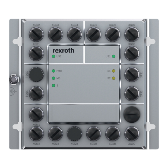
Seite 23: Schnittstellenübersicht
R911381901 | Rexroth PRC7000 MGDM Bosch Rexroth AG 23/118 Schnittstellenübersicht Abb. 2: Bezeichnung der Schnittstellen am MGDM... -
Seite 24: Xds1 Power In
24/118 Bosch Rexroth AG R911381901 | Rexroth PRC7000 MGDM XDS1 Power IN Steckerbelegung XDS1 Abb. 3: XDS1 Belegung Hinweis: Polbild bei Blick von oben auf das MGDM Anschluss XDS1 (Einspeisung Versorgungsspannungen) Abb. 4: Anschlussbild XDS1... -
Seite 25: Xds2 Power Out
R911381901 | Rexroth PRC7000 MGDM Bosch Rexroth AG 25/118 XDS2 Power OUT Steckerbelegung XDS2 Abb. 5: XDS2 Belegung Hinweis: Polbild bei Blick von oben auf das MGDM Anschluss XDS2 (Einspeisung Versorgungsspannungen) Abb. 6: Anschlussbild XDS2... -
Seite 26: Xgm1 Trafo 1
26/118 Bosch Rexroth AG R911381901 | Rexroth PRC7000 MGDM XGM1 Trafo 1 Steckerbelegung XGM1 Abb. 7: XGM1 Belegung Hinweis: Polbild bei Blick von oben auf das MGDM Anschluss XGM1 Trafo 1 Abb. 8: Anschlussbild XGM1... -
Seite 27: Xgm2 Trafo 2
R911381901 | Rexroth PRC7000 MGDM Bosch Rexroth AG 27/118 XGM2 Trafo 2 Steckerbelegung XGM2 Abb. 9: XGM2 Belegung Hinweis: Polbild bei Blick von oben auf das MGDM Anschluss XGM2 Trafo 2 Abb. 10: Anschlussbild XGM2... -
Seite 28: Xgm3 Druck
28/118 Bosch Rexroth AG R911381901 | Rexroth PRC7000 MGDM 10 XGM3 Druck 10.1 Steckerbelegung XGM3 Abb. 11: XGM3 Belegung Hinweis: Polbild bei Blick von oben auf das MGDM... -
Seite 29: Anschluss Xgm3 (Druckregelventil)
R911381901 | Rexroth PRC7000 MGDM Bosch Rexroth AG 29/118 10.2 Anschluss XGM3 (Druckregelventil) 10.2.1 FESTO VPPM-…C1 Proportional-Druckregelventil z.B. VPPM-…-V1P-.. mit +24V-Versorgung, Spannungs-Sollwert 0…+10V, Schaltausgang PNP Abb. 12: Anschlussbeispiel mit Spannungs-Sollwert z.B. VPPM-…-A4P-.. mit +24V-Versorgung, Strom-Sollwert 0…20mA, Schaltausgang PNP Abb. 13: Anschlussbeispiel mit Strom-Sollwert... -
Seite 30: Aventics E/P Druckregelventil, Serie Ed05
30/118 Bosch Rexroth AG R911381901 | Rexroth PRC7000 MGDM 10.2.2 AVENTICS E/P Druckregelventil, Serie ED05 z.B. mit +24V-Versorgung, Spg.-Sollwert 0…+10V, Spg.-Istwert 0…+10V Abb. 14: Anschlussbeispiel mit Spannungs-Sollwert z.B. mit +24V-Versorgung, Strom-Sollwert 0…20mA, digi. Druck- Rückmeldung Abb. 15: Anschlussbeispiel mit Strom-Sollwert... -
Seite 31: Xgm4 Sekundärspannung
Abb. 16: XGM4 Belegung Hinweis: Polbild bei Blick von oben auf das MGDM 11.2 Anschluss XGM4 (Sekundärspannung) Die Steckerbelegung von XGM4 ist pinkompatibel zu dem Anschlussstecker Uin an Bosch Rexroth Schweiß-Transformatoren. Eine geschirmte Anschlussleitung an XGM4 wird empfohlen. Abb. 17: Anschlussbild XGM4... -
Seite 32: Xgm5 Kraft 1
32/118 Bosch Rexroth AG R911381901 | Rexroth PRC7000 MGDM 12 XGM5 Kraft 1 12.1 Steckerbelegung XGM5 Abb. 18: XGM5 Belegung Hinweis: Polbild bei Blick von oben auf das MGDM 12.2 Anschluss XGM5 (Kraftsensor 1) Die Anschlussleitung an XGM5 muss geschirmt sein. -
Seite 33: Xgm6 Kraft 2
R911381901 | Rexroth PRC7000 MGDM Bosch Rexroth AG 33/118 13 XGM6 Kraft 2 13.1 Steckerbelegung XGM6 Abb. 20: XGM6 Belegung Hinweis: Polbild bei Blick von oben auf das MGDM 13.2 Anschluss XGM6 (Kraftsensor 2) Die Anschlussleitung an XGM6 muss geschirmt sein. -
Seite 34: Xgd0 Kodierung
34/118 Bosch Rexroth AG R911381901 | Rexroth PRC7000 MGDM 14 XGD0 Kodierung 14.1 Steckerbelegung XGD0 Abb. 22: XGD0 Belegung Hinweis: Polbild bei Blick von oben auf das MGDM 14.2 Anschluss XGD0 (Modul-Kodierung) 14.2.1 z.B. MGDM-Modul an Roboterzange mit Kodierung ‚ 0‘... -
Seite 35: Mgdm-Modul An Handzange 1 Mit Kodierung ' 1
R911381901 | Rexroth PRC7000 MGDM Bosch Rexroth AG 35/118 14.2.2 z.B. MGDM-Modul an Handzange 1 mit Kodierung ‚ 1‘ Abb. 24: Anschlussbild XGD0 Kodierung ‚ 1‘ 14.2.3 z.B. MGDM-Modul an Handzange 2 mit Kodierung ‚ 2‘ Abb. 25: Anschlussbild XGD0 Kodierung ‚ 2‘... -
Seite 36: Konfigurierbare Ein/Ausgänge
36/118 Bosch Rexroth AG R911381901 | Rexroth PRC7000 MGDM Abb. 26: LEDs für Versorgungsspannungen U und U 15.1.2 Konfigurierbare Ein/Ausgänge Im Anschlussfeld Diskrete 24V Ein/Ausgänge stehen insgesamt 24 diskrete 24V Ein/Ausgangs-Signale zur Verfügung, gruppiert in 3 EA-Gruppen mit je 8 Ein/Ausgängen:... -
Seite 37: Beispiele Für Sensor/Actor-Einheiten
R911381901 | Rexroth PRC7000 MGDM Bosch Rexroth AG 37/118 Abb. 27: Verteilung der EAs auf die Steckverbinder EA00..EA23 Jeder Steckverbinder enthält neben den Anschlüssen für die Ein/Ausgangs- Signale jeweils noch die jeweiligen Anschlüsse der Versorgungsspannung US2 bzw. US1 zur Versorgung der Sensoren/Actor-Einheiten. -
Seite 38: Direkter Anschluss Ventil-Steckverbinder
38/118 Bosch Rexroth AG R911381901 | Rexroth PRC7000 MGDM 4-fach Sensor/Actor-Einheit • Beispiele für einen 4-fach Sensor: Programmanwahl-Drehschalter, spez. Schalter-Einheit, usw. • Beispiele für einen 4-fach Actor: 7-Segment Anzeige, Stacklight rot/gelb/grün, usw. • Beispiele für eine 4-fach Einheit: spez. Einheit mit beliebiger Kombination Sensoren oder Aktoren. -
Seite 39: Besonderheit Y-Verteiler Steckverbinder
R911381901 | Rexroth PRC7000 MGDM Bosch Rexroth AG 39/118 Abb. 33: Anschlussbild Steckverbinder 15.1.6 Besonderheit Y-Verteiler Steckverbinder Die Steckverbinder XGD1, XGD2, XGD3, XGD4 und XGD5 kontaktieren 2 EA- Signale (für z.B. 2-fach Sensor/Actor Einheit). Hier können einfach einzelne 1- fach Sensor/Actor-Einheiten angeschlossen werden, wobei dann das zweite EA- Signal nicht mehr zur Verfügung steht. - Seite 40 40/118 Bosch Rexroth AG R911381901 | Rexroth PRC7000 MGDM Abb. 36: Beispiel Anschluss XGDx über Y-Verteiler 4polig mit Selektion S1/S2 Abb. 37: Anschlussbild Y-Verteiler 4polig mit Selektion S1/S2...
-
Seite 41: Xgd1 Diskrete 24V-Ein/Ausgänge (2-Fach)
R911381901 | Rexroth PRC7000 MGDM Bosch Rexroth AG 41/118 15.2 XGD1 Diskrete 24V-Ein/Ausgänge (2-fach) 15.2.1 Steckerbelegung XGD1 Abb. 38: XGD1 Belegung Hinweis: Polbild bei Blick von oben auf das MGDM 15.2.2 Anschluss XGD1 (Diskrete 24V-Ein/Ausgänge 2-fach) Abb. 39: Anschlussbild XGD1 15.2.3 Beispiel Anschluss Ventil an XGD1... -
Seite 42: Xgd2 Diskrete 24V-Ein/Ausgänge (2-Fach)
42/118 Bosch Rexroth AG R911381901 | Rexroth PRC7000 MGDM 15.3 XGD2 Diskrete 24V-Ein/Ausgänge (2-fach) 15.3.1 Steckerbelegung XGD2 Abb. 41: XGD2 Belegung Hinweis: Polbild bei Blick von oben auf das MGDM 15.3.2 Anschluss XGD2 (Diskrete 24V-Ein/Ausgänge 2-fach) Abb. 42: Anschlussbild XGD2... -
Seite 43: Xgd3 Diskrete 24V-Ein/Ausgänge (2-Fach)
R911381901 | Rexroth PRC7000 MGDM Bosch Rexroth AG 43/118 15.4 XGD3 Diskrete 24V-Ein/Ausgänge (2-fach) 15.4.1 Steckerbelegung XGD3 Abb. 43: XGD3 Belegung Hinweis: Polbild bei Blick von oben auf das MGDM 15.4.2 Anschluss XGD3 (Diskrete 24V-Ein/Ausgänge 2-fach) Abb. 44: Anschlussbild XGD3... -
Seite 44: Xgd4 Diskrete 24V-Ein/Ausgänge (2-Fach)
44/118 Bosch Rexroth AG R911381901 | Rexroth PRC7000 MGDM 15.5 XGD4 Diskrete 24V-Ein/Ausgänge (2-fach) 15.5.1 Steckerbelegung XGD4 Abb. 45: XGD4 Belegung Hinweis: Polbild bei Blick von oben auf das MGDM 15.5.2 Anschluss XGD4 (Diskrete 24V-Ein/Ausgänge 2-fach) Abb. 46: Anschlussbild XGD4... -
Seite 45: Xgd5 Diskrete 24V-Ein/Ausgänge (2-Fach)
R911381901 | Rexroth PRC7000 MGDM Bosch Rexroth AG 45/118 15.6 XGD5 Diskrete 24V-Ein/Ausgänge (2-fach) 15.6.1 Steckerbelegung XGD5 Abb. 47: XGD5 Belegung Hinweis: Polbild bei Blick von oben auf das MGDM 15.6.2 Anschluss XGD5 (Diskrete 24V-Ein/Ausgänge 2-fach) Abb. 48: Anschlussbild XGD5... -
Seite 46: Xgd6 Diskrete 24V-Ein/Ausgänge (4-Fach)
46/118 Bosch Rexroth AG R911381901 | Rexroth PRC7000 MGDM 15.7 XGD6 Diskrete 24V-Ein/Ausgänge (4-fach) 15.7.1 Steckerbelegung XGD6 Abb. 49: XGD6 Belegung Hinweis: Polbild bei Blick von oben auf das MGDM 15.7.2 Anschluss XGD6 (Diskrete 24V-Ein/Ausgänge 4-fach) Abb. 50: Anschlussbild XGD6... -
Seite 47: Xgd7 Diskrete 24V-Ein/Ausgänge (4-Fach)
R911381901 | Rexroth PRC7000 MGDM Bosch Rexroth AG 47/118 15.8 XGD7 Diskrete 24V-Ein/Ausgänge (4-fach) 15.8.1 Steckerbelegung XGD7 Abb. 51: XGD7 Belegung Hinweis: Polbild bei Blick von oben auf das MGDM 15.8.2 Anschluss XGD7 (Diskrete 24V-Ein/Ausgänge 4-fach) Abb. 52: Anschlussbild XGD7... -
Seite 48: Xgd8 Diskrete 24V-Ein/Ausgänge (6-Fach)
48/118 Bosch Rexroth AG R911381901 | Rexroth PRC7000 MGDM 15.9 XGD8 Diskrete 24V-Ein/Ausgänge (6-fach) 15.9.1 Steckerbelegung XGD8 Abb. 53: XGD8 Belegung Hinweis: Polbild bei Blick von oben auf das MGDM 15.9.2 Anschluss XGD8 (Diskrete 24V-Ein/Ausgänge 6-fach) Abb. 54: Anschlussbild XGD8... -
Seite 49: Xfs1 Bus 1
R911381901 | Rexroth PRC7000 MGDM Bosch Rexroth AG 49/118 15.10 XFS1 Bus 1 15.10.1 Steckerbelegung XFS1 Abb. 55: XFS1 Belegung Hinweis: Polbild bei Blick von oben auf das MGDM 15.10.2 Anschluss XFS1 (Bus 1) Die Anschlussleitung an XFS1 muss geschirmt sein. -
Seite 50: Xfs2 Bus 2
50/118 Bosch Rexroth AG R911381901 | Rexroth PRC7000 MGDM 15.11 XFS2 Bus 2 15.11.1 Steckerbelegung XFS2 Abb. 57: XFS2 Belegung Hinweis: Polbild bei Blick von oben auf das MGDM 15.11.2 Anschluss XFS2 (Bus 2) Die Anschlussleitung an XFS2 muss geschirmt sein. -
Seite 51: Leds
R911381901 | Rexroth PRC7000 MGDM Bosch Rexroth AG 51/118 16 LEDs Merkmale: An der Frontseite des MGDM sind 7 Diagnose-LEDs angeordnet. Tab. 8: LED „ US1“ Versorgungsspannung 1 Zustand Bedeutung Leuchtet nicht Keine Versorgungsspannung Grün Versorgungsspannung US1 vorhanden Tab. 9: LED „ US2“ Versorgungsspannung 2... -
Seite 52: Transport Und Lagerung
52/118 Bosch Rexroth AG R911381901 | Rexroth PRC7000 MGDM Blinkt einmal orange Device ist in Hot Plug Phase 1 dann grün permanent Blinkt 2 mal orange Device ist in Hot Plug Phase 2 dann grün permanent Blinkt grün RT-Status hat gewechselt von fast-forward zu loopback... -
Seite 53: Maßbild Und Anschlusspositionen
R911381901 | Rexroth PRC7000 MGDM Bosch Rexroth AG 53/118 • Funktionserde Verbindung zum geerdeten Zangengrundkörper herstellen. Empfehlung 2,5mm² Leitung. • Mitgelieferte Schutzkappen montieren 18.2 Maßbild und Anschlusspositionen Abb. 59: Maßbild MGDM Vorderansicht und Seitenansicht... -
Seite 54: Inbetriebnahme
54/118 Bosch Rexroth AG R911381901 | Rexroth PRC7000 MGDM Abb. 60: Anschlusspositionen mit Winkelstecker 19 Inbetriebnahme Voraussetzung zur Inbetriebnahme ist die ordnungsgemäße Installation und Funktion • aller Not-Aus-Einrichtungen • des elektrischen Anschlusses inkl. aller benötigten Sensoren Stellen Sie sicher, dass die genannten Voraussetzungen zur Inbetriebnahme gegeben sind. -
Seite 55: Betrieb Als Einfache Sercos Io Insel
R911381901 | Rexroth PRC7000 MGDM Bosch Rexroth AG 55/118 Kodierung über XGD0 am MGDM gleich 0: (siehe auch Kap.14 XGD0 Kodierung) Adresse wird vom integrierten Drehschalter abgeleitet: • Drehschalter < 8: Sercos-Adresse = (30 + Drehschalter) IP-Adresse = 192.168.0. (30 + Drehschalter) •... -
Seite 56: Betrieb
56/118 Bosch Rexroth AG R911381901 | Rexroth PRC7000 MGDM Bei externer 24 V-Versorgung der Steuerungslogik (an US2) leuchtet die LED US2 weiter. 20 Betrieb Beachten Sie die Hinweise zum Betrieb des Produktes in Kap. 2 und 3.4. Wenn an den MGDM LEDs keine Störung ansteht, dann ist das MGDM bereit. -
Seite 57: Wiederverwertung
R911381901 | Rexroth PRC7000 MGDM Bosch Rexroth AG 57/118 Bürgermeister-Dr.-Nebel-Strasse 2 97816 Lohr am Main 22.2 Wiederverwertung Hauptbestandteile unserer Elektronikgerate: • Stahl, Aluminium, Kupfer, Kunststoffe. Durch den hohen Metallanteil können unsere Produkte überwiegend stofflich wieder verwertet werden. Um eine optimale Metallrückgewinnung zu erreichen, ist eine Demontage in einzelne Baugruppen erforderlich. - Seite 58 58/118 Bosch Rexroth AG R911381901 | Rexroth PRC7000 MGDM Temperaturüberwachung integriert Max. Höhe des 2000 m über NN Betriebsstandortes Klimaklasse 3K3 nach EN 60721-3-3 Luftfeuchtigkeit Betauung nicht zulässig Korrosion Die Umgebungsluft muss frei sein von hoheren Konzentrationen an Säuren, Laugen, Korrosionsmitteln, Salzen, Metalldämpfen...
-
Seite 59: Service Und Support
R911381901 | Rexroth PRC7000 MGDM Bosch Rexroth AG 59/118 25 Service und Support Sie erreichen unsere Service-Hotline und unseren Service-Helpdesk unter: Telefon: +49 9352 40 5060 Fax: +49 9352 18 4941 Service Deutschland E-Mail: service.svc@boschrexroth.de Internet:http://www.boschrexroth.com Auf unseren Internetseiten finden Sie ergänzende Hinweise zu Service, Reparatur (z. - Seite 60 60/118 Bosch Rexroth AG R911381901 | Rexroth PRC7000 MGDM • Ergänzung Kap. 16 LEDs SERCOS S1 und S2 • Kap. 19.1 Drehschalter < 8, Sercos-Adresse und IP-Adresse (30+Drehschalter) • Kap. 19.3 Betrieb mit nur einem Trafo • Neues Titelbild und Frontansicht...
- Seite 61 R911381901 | Rexroth PRC7000 MGDM Bosch Rexroth AG 61/118 Contents Regarding this Documentation ..............64 Validity of the documentation ............64 Required and supplementary documentation ........64 Display of information ............... 65 1.3.1 Safety instructions ............65 1.3.2 Symbols ................67 1.3.3...
- Seite 62 62/118 Bosch Rexroth AG | Electric Drives and Controls R911381901 | Rexroth PRC7000 MGDM Connection XGM2 Transformer 2 ............. 84 XGM3 Pressure ..................85 10.1 Pin assignment XGM3 ..............85 10.2 Connection XGM3 (pressure regulation valve) ......... 86 10.2.1 FESTO VPPM-…C1 Proportional pressure regulation valve ..................
- Seite 63 R911381901 | Rexroth PRC7000 MGDM Bosch Rexroth AG 63/118 15.6.1 Pin assignment XGD6 ............ 103 15.6.2 Connection XGD6 (Discrete 24V inputs/outputs 4-fold).. 103 15.7 XGD7 Discrete 24V inputs/outputs (4-fold) ........104 15.7.1 Pin assignment XGD7 ............ 104 15.7.2 Connection XGD7 (Discrete 24V inputs/outputs 4-fold).. 104 15.8...
-
Seite 64: Regarding This Documentation
64/118 Bosch Rexroth AG | Electric Drives and Controls R911381901 | Rexroth PRC7000 MGDM Regarding this Documentation Validity of the documentation This documentation applies to Rexroth MGDM Measuring Gun Data Module. The content belong to • Connection (power supply) • Functionality •... -
Seite 65: Display Of Information
R911381901 | Rexroth PRC7000 MGDM Bosch Rexroth AG 65/118 Display of information In order to enable you to work with your product in a fast and safe way, uniform Safety instructions, symbols, terms and abbreviations are used. For a better understanding they are explained in the following sections. - Seite 66 66/118 Bosch Rexroth AG | Electric Drives and Controls R911381901 | Rexroth PRC7000 MGDM Danger classes according to ANSI Z535.6 Tab. 3: Warning sign, Signal word Meaning Dangerous situation where death or serious physical DANGER injurieswill occur if it is not avoided.
-
Seite 67: Symbols
R911381901 | Rexroth PRC7000 MGDM Bosch Rexroth AG 67/118 1.3.2 Symbols The following symbols mark notes that are not safety-relevant but increase the understanding of the documentation. Meaning of the symbols Tab. 5: Symbol Meaning If this information is disregarded, the product cannot be used and or operated to the optimum extent. -
Seite 68: Safety Instructions
68/118 Bosch Rexroth AG | Electric Drives and Controls R911381901 | Rexroth PRC7000 MGDM Safety instructions This section includes important information on the safe handling of the described product. On this section The described product has been developed, manufactured, tested and documented in compliance with the EU standards. -
Seite 69: Qualification Of Personnel
• operation or storage outside the specified environmental conditions (e.g. air humidity), • electrical connection does not correspond to documentation. Bosch Rexroth AG does not assume any liability for damages caused by inappropriate use. The risks resulting from inappropriate use are borne by the operator/user alone. -
Seite 70: General Safety Instructions
70/118 Bosch Rexroth AG | Electric Drives and Controls R911381901 | Rexroth PRC7000 MGDM Training options For the latest information on training courses, teachware and training systems please refer to www.boschrexroth.com/training. For more information, you may also contact Bosch Rexroth AG... -
Seite 71: Transport
R911381901 | Rexroth PRC7000 MGDM Bosch Rexroth AG 71/118 2.6.2 Transport CAUTION Sharp metal edges! Higher risk of injuries through cutting! Wear appropriate working clothes and use suitable protective equipment (e.g. protective helmet/shoes, protective gloves). 2.6.3 Installation and assembly... -
Seite 72: Electrical Connection
72/118 Bosch Rexroth AG | Electric Drives and Controls R911381901 | Rexroth PRC7000 MGDM 2.6.4 Electrical connection WARNING Defective or incomplete connection of I/O signals Possibility of reduction of safety of persons/systems, function disturbances/restrictions! Any user, line supplier, welding machine manufacturer and welding ... -
Seite 73: Operating The Product
R911381901 | Rexroth PRC7000 MGDM Bosch Rexroth AG 73/118 2.6.5 Operating the product WARNING High dynamic forces and extremely fast movements Danger of impacts, bruises, entanglement and burns! You should always be aware of the possibility that motions can be ... -
Seite 74: Maintenance And Repair
74/118 Bosch Rexroth AG | Electric Drives and Controls R911381901 | Rexroth PRC7000 MGDM 2.6.7 Maintenance and repair WARNING Employing unqualified personnel Possibility of reduction of safety of persons/systems, function disturbances/restrictions! Make sure that repair and maintenance work is performed by our ... -
Seite 75: Transport And Storage
R911381901 | Rexroth PRC7000 MGDM Bosch Rexroth AG 75/118 Transport and storage NOTICE Frost, corrosion Possibility of short-circuits, damage to electrical equipment, unexpected plant reactions! Please note the minimum and maximum storage temperature range of all components (refer to information provided in the technical data). -
Seite 76: Electrical Connection
76/118 Bosch Rexroth AG | Electric Drives and Controls R911381901 | Rexroth PRC7000 MGDM Electrical connection NOTICE Incorrect voltage supply Possibility of damage to the electrical equipment! Check whether the supply voltage coincides with the nominal voltage indicated on the nameplate of the product! The product may only connected to the mains if these values coincide. -
Seite 77: Operation
R911381901 | Rexroth PRC7000 MGDM Bosch Rexroth AG 77/118 NOTICE Electrostatic charge Possibility of damage to the electrical equipment! Observe all precautions for ESD protection when handling modules and components and avoid electrostatic discharge. Observe the following protective measures for modules and ... -
Seite 78: Maintenance And Repair
78/118 Bosch Rexroth AG | Electric Drives and Controls R911381901 | Rexroth PRC7000 MGDM NOTICE Plugging or unplugging modules or connectors/terminals into/fromlive systems Possibility of damage to the electrical equipment, unexpected plant reactions! Unless described otherwise, never unplug or plug any connectors/ ... -
Seite 79: Scope Of Delivery
R911381901 | Rexroth PRC7000 MGDM Bosch Rexroth AG 79/118 Scope of delivery The scope of delivery is dependent on the order. Therefore we cannot provide any globally valid information on the scope of your specific delivery. Check the scope of delivery against the delivery note. -
Seite 80: Interfaces Overview
80/118 Bosch Rexroth AG | Electric Drives and Controls R911381901 | Rexroth PRC7000 MGDM Interfaces overview Fig. 2: Desigantion of the interfaces from the MGDM... -
Seite 81: Xds1 Power In
R911381901 | Rexroth PRC7000 MGDM Bosch Rexroth AG 81/118 XDS1 Power IN Pin assignment XDS1 Fig. 3: XDS1 assignment Note: Contact arrangement view from above the MGDM Connection XDS1 (voltage supply) Fig. 4: Circuit diagram XDS1... -
Seite 82: Xds2 Power Out
82/118 Bosch Rexroth AG | Electric Drives and Controls R911381901 | Rexroth PRC7000 MGDM XDS2 Power OUT Pin assignment XDS2 Fig. 5: XDS2 assignment Note: Contact arrangement view from above the MGDM Connection XDS2 (voltage supply) Fig. 6: Circuit diagram XDS2... -
Seite 83: Xgm1 Trafo 1
R911381901 | Rexroth PRC7000 MGDM Bosch Rexroth AG 83/118 XGM1 Trafo 1 Pin assignment XGM1 Fig. 7: XGM1 assignment Note: Contact arrangement view from above the MGDM Connection XGM1 Transformer 1 Fig. 8: Circuit diagram XGM1... -
Seite 84: Xgm2 Trafo 2
84/118 Bosch Rexroth AG | Electric Drives and Controls R911381901 | Rexroth PRC7000 MGDM XGM2 Trafo 2 Pin assignment XGM2 Fig. 9: XGM2 assignment Note: Contact arrangement view from above the MGDM Connection XGM2 Transformer 2 Fig. 10: Circuit diagram XGM2... -
Seite 85: Xgm3 Pressure
R911381901 | Rexroth PRC7000 MGDM Bosch Rexroth AG 85/118 10 XGM3 Pressure 10.1 Pin assignment XGM3 Fig. 11: XGM3 assignment Note: Contact arrangement view from above the MGDM... -
Seite 86: Connection Xgm3 (Pressure Regulation Valve)
86/118 Bosch Rexroth AG | Electric Drives and Controls R911381901 | Rexroth PRC7000 MGDM 10.2 Connection XGM3 (pressure regulation valve) 10.2.1 FESTO VPPM-…C1 Proportional pressure regulation valve e.g. VPPM-…-V1P-.. with +24V supply, voltage setpoint 0…+10V, switched output PNP Fig. 12: Circuit diagram example with voltage setpoint e.g. -
Seite 87: Aventics E/P Pressure Regulation Valve, Series Ed05
R911381901 | Rexroth PRC7000 MGDM Bosch Rexroth AG 87/118 10.2.2 AVENTICS E/P pressure regulation valve, series ED05 e.g. with +24V voltage, voltage setpoint 0…+10V, actual voltage 0…+10V Fig. 14: Circuit diagram example with voltage setpoint e.g. with +24V supply, current setpoint 0…20mA, digital pressure feedback Fig. -
Seite 88: Xgm4 Secondary Voltage
Note: Contact arrangement view from above the MGDM 11.2 Connection XGM4 (Secondary voltage) The pin assignment of XGM4 is pin compatible to the plug type terminal Uin at Bosch Rexroth welding transformers. A shielded connection cable to XGM4 is recommended. Fig. 17:... -
Seite 89: Xgm5 Force 1
R911381901 | Rexroth PRC7000 MGDM Bosch Rexroth AG 89/118 12 XGM5 Force 1 12.1 Pin assignment XGM5 Fig. 18: XGM5 assignment Note: Contact arrangement view from above the MGDM 12.2 Connection XGM5 (force sensor 1) The connecting cable to XGM5 must be shielded. -
Seite 90: Xgm6 Force 2
90/118 Bosch Rexroth AG | Electric Drives and Controls R911381901 | Rexroth PRC7000 MGDM 13 XGM6 Force 2 13.1 Pin assignment XGM6 Fig. 20: XGM6 assignment Note: Contact arrangement view from above the MGDM 13.2 Connection XGM6 (force sensor 2) The connecting cable to XGM6 must be shielded. -
Seite 91: Xgd0 Coding
R911381901 | Rexroth PRC7000 MGDM Bosch Rexroth AG 91/118 14 XGD0 coding 14.1 Pin assignment XGD0 Fig. 22: XGD0 assignment Note: Contact arrangement view from above the MGDM 14.2 Connection XGD0 (module coding) 14.2.1 e.g. MGDM module to robot gun with coding ‚ 0‘... -
Seite 92: Mgdm Module To Manual Gun 1 With Coding ' 1
92/118 Bosch Rexroth AG | Electric Drives and Controls R911381901 | Rexroth PRC7000 MGDM 14.2.2 e.g. MGDM module to manual gun 1 with coding ‚ 1‘ Fig. 24: Circuit diagram XGD0 coding ‚ 1‘ 14.2.3 e.g. MGDM module to manual gun 2 with coding ‚ 2‘... -
Seite 93: Configurable Inputs/Outputs
R911381901 | Rexroth PRC7000 MGDM Bosch Rexroth AG 93/118 Fig. 26: LEDs for supply voltages U and U 15.1.2 Configurable inputs/outputs In the connection field discrete 24V inputs/outputs are overall 24 discrete 24V input/output signals available , grouped in 3 IO-groups per 8 inputs/outputs: EA00 …... -
Seite 94: Examples For Sensor/Actor Units
94/118 Bosch Rexroth AG | Electric Drives and Controls R911381901 | Rexroth PRC7000 MGDM Fig. 27: Distribution of EAs on the plug connector EA00..EA23 Each plug connector contain, beside the connections for the input/output signals, the respective connections for the voltage supplies US2 or US1 to supply the sensor/actor units. -
Seite 95: Direct Connection Plug Connector
R911381901 | Rexroth PRC7000 MGDM Bosch Rexroth AG 95/118 4-fold Sensor/Actor unit • Examples for a 4-fold Sensor: Program selection rotary switch, specified switch unit, etc. • Examples for a 4-fold Actor: 7-segment display, Stacklight red/yellow/green, etc. • Examples for a 4-fold unit: specified unit with any combination sensors or actors. -
Seite 96: Special Feature Y-Distributor Plug Connector
96/118 Bosch Rexroth AG | Electric Drives and Controls R911381901 | Rexroth PRC7000 MGDM Fig. 33: Circuit diagram plug connector 15.1.6 Special feature Y-distributor plug connector The plug connector XGD1, XGD2, XGD3, XGD4 and XGD5 contact 2 IO signals (for e.g. 2-fold sensor/actor unit). - Seite 97 R911381901 | Rexroth PRC7000 MGDM Bosch Rexroth AG 97/118 Fig. 36: Example Y-distributor plug connector XGDx 4-pole with selection S1/S2 Fig. 37: Circuit diagram Y-distributor 4-pole with selection S1/S2...
-
Seite 98: Xgd1 Discrete 24V Inputs/Outputs (2-Fold)
98/118 Bosch Rexroth AG | Electric Drives and Controls R911381901 | Rexroth PRC7000 MGDM 15.2 XGD1 discrete 24V inputs/outputs (2-fold) 15.2.1 Pin assignment XGD1 Fig. 38: XGD1 assignment Note: Contact arrangement view from above the MGDM 15.2.2 Connection XGD1 (discrete 24V inputs/outputs 2-fold) Fig. -
Seite 99: Xgd2 Discrete 24V Inputs/Outputs (2-Fold)
R911381901 | Rexroth PRC7000 MGDM Bosch Rexroth AG 99/118 15.3 XGD2 Discrete 24V inputs/outputs (2-fold) 15.3.1 Pin assignment XGD2 Fig. 41: XGD2 assignment Note: Contact arrangement view from above the MGDM 15.3.2 Connection XGD2 (Discrete 24V inputs/outputs 2-fold)) Fig. 42:... -
Seite 100: Xgd3 Discrete 24V Inputs/Outputs (2-Fold)
100/118 Bosch Rexroth AG | Electric Drives and Controls R911381901 | Rexroth PRC7000 MGDM XGD3 Discrete 24V inputs/outputs (2-fold) 15.3.3 Pin assignment XGD3 Fig. 43: XGD3 assignment Note: Contact arrangement view from above the MGDM 15.3.4 Connection XGD3 (Discrete 24V inputs/outputs 2-fold) Fig. -
Seite 101: Xgd4 Discrete 24V Inputs/Outputs (2-Fold)
R911381901 | Rexroth PRC7000 MGDM Bosch Rexroth AG 101/118 15.4 XGD4 Discrete 24V inputs/outputs (2-fold) 15.4.1 Pin assignment XGD4 Fig. 45: XGD4 assignment Note: Contact arrangement view from above the MGDM 15.4.2 Connection XGD4 (Discrete 24V inputs/outputs 2-fold) Fig. 46:... -
Seite 102: Xgd5 Discrete 24V Inputs/Outputs (2-Fold)
102/118 Bosch Rexroth AG | Electric Drives and Controls R911381901 | Rexroth PRC7000 MGDM 15.5 XGD5 Discrete 24V inputs/outputs (2-fold) 15.5.1 Pin assignment XGD5 Fig. 47: XGD5 assignment Note: Contact arrangement view from above the MGDM 15.5.2 Connection XGD5 (Discrete 24V inputs/outputs 2-fold) Fig. -
Seite 103: Xgd6 Discrete 24V Inputs/Outputs (4-Fold)
R911381901 | Rexroth PRC7000 MGDM Bosch Rexroth AG 103/118 15.6 XGD6 Discrete 24V inputs/outputs (4-fold) 15.6.1 Pin assignment XGD6 Fig. 49: XGD6 assignment Note: Contact arrangement view from above the MGDM 15.6.2 Connection XGD6 (Discrete 24V inputs/outputs 4-fold) Fig. 50:... -
Seite 104: Xgd7 Discrete 24V Inputs/Outputs (4-Fold)
104/118 Bosch Rexroth AG | Electric Drives and Controls R911381901 | Rexroth PRC7000 MGDM 15.7 XGD7 Discrete 24V inputs/outputs (4-fold) 15.7.1 Pin assignment XGD7 Fig. 51: XGD7 assignment Note: Contact arrangement view from above the MGDM 15.7.2 Connection XGD7 (Discrete 24V inputs/outputs 4-fold) Fig. -
Seite 105: Xgd8 Discrete 24V Inputs/Outputs (6-Fold)
R911381901 | Rexroth PRC7000 MGDM Bosch Rexroth AG 105/118 15.8 XGD8 Discrete 24V inputs/outputs (6-fold) 15.8.1 Pin assignment XGD8 Fig. 53: XGD8 assignment Note: Contact arrangement view from above the MGDM 15.8.2 Connection XGD8 (Discrete 24V inputs/outputs 6-fold) Fig. 54:... -
Seite 106: Xfs1 Bus 1
106/118 Bosch Rexroth AG | Electric Drives and Controls R911381901 | Rexroth PRC7000 MGDM 15.9 XFS1 Bus 1 15.9.1 Pin assignment XFS1 Fig. 55: XFS1 assignment Note: Contact arrangement view from above the MGDM 15.9.2 Connection XFS1 (Bus 1) The connecting cable to XFS1 must be shielded. -
Seite 107: Xfs2 Bus 2
R911381901 | Rexroth PRC7000 MGDM Bosch Rexroth AG 107/118 15.10 XFS2 Bus 2 15.10.1 Pin assignment XFS2 Fig. 57: XFS2 assignment Note: Contact arrangement view from above the MGDM 15.10.2 Connection XFS2 (Bus 2) The connecting cable to XFS2 must be shielded. -
Seite 108: Leds
108/118 Bosch Rexroth AG | Electric Drives and Controls R911381901 | Rexroth PRC7000 MGDM 16 LEDs Features: At the front part of the MGDM are arranged 7 Diagnosis LEDs. LED „ US1“ supply voltage 1 Tab. 8: State Meaning dark... -
Seite 109: Transport And Storage
R911381901 | Rexroth PRC7000 MGDM Bosch Rexroth AG 109/118 permanent flashing 2 times Device is in hot plug phase 2 orange then green permanent flashing green RT-Status has changed from fast-forward to loopback flashing red and Application error orange in... -
Seite 110: Dimensioned Drawing And Locations Of Connections
110/118 Bosch Rexroth AG | Electric Drives and Controls R911381901 | Rexroth PRC7000 MGDM • Connect Function ground at threaded pin (refer to Fig.59). • Make a functional earth connection to the grounded gun base body. Recommendation 2.5mm² cable. • Mounting of provided protection caps 18.2 Dimensioned drawing and locations of connections... -
Seite 111: Commissioning
R911381901 | Rexroth PRC7000 MGDM Bosch Rexroth AG 111/118 Fig. 60: Locations of connections with angle plugs 19 Commissioning Prerequisite for commissioning is the proper installation and function • of all Emergency-Stop/Emergency-Halt devices • of the electrical connection including all required sensors Make sure that the above mentioned prerequisites for commissioning are met. -
Seite 112: Operation As Simple Sercos Io Module
112/118 Bosch Rexroth AG | Electric Drives and Controls R911381901 | Rexroth PRC7000 MGDM Address is derived from the integrated turn-switch: • Turn-switch < 8: Sercos address = (30 + turn-switch) IP adress = 192.168.0. (30 + turn-switch) • Turn-switch >= 8: Sercos address = (14 + turn-switch) IP address = 192.168.0. -
Seite 113: Operation
R911381901 | Rexroth PRC7000 MGDM Bosch Rexroth AG 113/118 20 Operation Please note the instructions on operation of the product in section 2 and 3.4. If at the MGDM LEDs are no faults, then is the MGDM ready. Refer to the section 16 for the meaning of the LEDs. -
Seite 114: Environmental Protection
114/118 Bosch Rexroth AG | Electric Drives and Controls R911381901 | Rexroth PRC7000 MGDM can be recycled. In order to ensure optimum recovery of metals, the equipment has to be split into individual components. The metals that are contained in the electric and electronic modules can also be recovered using special separating methods. -
Seite 115: Service And Support
R911381901 | Rexroth PRC7000 MGDM Bosch Rexroth AG 115/118 Tab. 18: Electrical data Power supply power Typ. 24 V DC (US1) Supply voltage for the Via external 24 V DC power supply unit (PELV) Logic Nominal current Logic approx. 0,2 A (24 VDC without additional consumers... -
Seite 116: Updates
116/118 Bosch Rexroth AG | Electric Drives and Controls R911381901 | Rexroth PRC7000 MGDM 26 Updates 26.1 Version 01 • Title figure updated • Transport Safety instructions • Directives and Standards updated • Connect Function ground (refer to Fig.59). • Mount of provided protection caps •... - Seite 117 R911381901 | Rexroth PRC7000 MGDM Bosch Rexroth AG 117/118...
- Seite 118 The Drive & Control Company Bosch Rexroth AG Electric Drives and Controls P.O. Box 13 57 97803 Lohr, Germany Bgm.-Dr.-Nebel-Str. 2 97816 Lohr, Germany Tel. +49 9352 18 0 +49 9352 18 8400 www.boschrexroth.com/electrics DOK-PRC700-MGDM*******-IT03-D0-P...