
Verwandte Anleitungen für AMO AMOSIN WMI-110


Inhaltszusammenfassung für AMO AMOSIN WMI-110
- Seite 1 AMO Automatisierung esstechnik ptik GmbH ® AMOSIN Induktives Winkelmesssystem Inductive Angle Measuring System Montageanleitung Installation and Mounting Instructions WMI-110/210...
- Seite 2 Warranty: AMO Automatisierung Messtechnik Optik GmbH gewährt auf die Komponenten der AMO Automatisierung Messtechnik Optik GmbH shall grant a warranty period of 24 Winkelmesssysteme WMI-110/210 eine Gewährleistungszeit von 24 Monaten ab months from the date of delivery on the components of the WMI-110/210 angle Lieferdatum.
- Seite 3 Die WMI-110/210 Winkelmesssysteme (siehe auch: www.amo-gmbh.com) bestehen aus (Bilder nächste Doppelseite) : The WMI-110/210 Angle Measuring Systems (see also www.amo-gmbh.com) consists of (figures next two pages): Maßverkörperung - ist ein Messring (3) WMR-110 zum montieren direkt auf die Kundenmechanik.
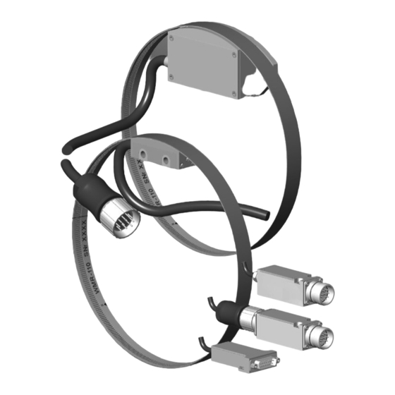
- Seite 4 Lieferumfang WMI-110 Abtastkopf WMK-11 items supplied WMI-110 Scanning head WMK-11 Abstandsfolie 0,15 mm Spacer film 0.15mm Messring WMR-110 Measuring ring WMR-110 Signalkonditionierung in Stecker integriert Signal conditioning integrated in connector Montageanleitung Mounting instructions Prüfzertifikat Test certificate Messprotokoll (Option) Calibration chart (optional) Verlängerungskabel (Option) Extension cable (optional)
- Seite 5 Lieferumfang WMI-210 Abtastkopf WMK-21 items supplied WMI-210 Scanning head WMK-21 Abstandsfolie 0,15 mm Spacer film 0.15mm Messring WMR-110 Measuring ring WMR-110 Montageanleitung Mounting instructions Prüfzertifikat Test certificate Messprotokoll (Option) Calibration chart (optional) Verlängerungskabel (Option) Extension cable (optional) WMI-110/210...
- Seite 6 Abmessungen WMK-110 dimensions WMK-110 WMK-110...
- Seite 7 Abmessungen WMK-210 dimensions WMK-210 WMK-210 WMI-110/210...
- Seite 8 Messring WMR-110 / Measuring Ring WMR-110 Montagezeichnung / Assembly drawing: Breite 10 mm Ausdehnungskoeffizient: ~11ppm Flanschmaterial: kein spezielles Material notwendig ØB: Durchmesser des Flansches ohne Maßverkörperung ØS: Durchmesser der Anschlagschulter * Rundlaufempfehlung Width 10 mm Höhere Rundlaufwerte bis ~0,05 mm haben keinen Einfluss auf die Coefficient of expansion: ~11 ppm Funktionen des Gerätes, beeinträchtigen aber verhältnismäßig die Positioniergenauigkeit.
- Seite 9 Standard Messringe im Lieferprogramm:: WMR-11 - ... 0512, 0720, 0900, 1024, 1440, 2048 Weitere Strichzahlen werden auf Anfrage angeboten. Standard program measuring rings: WMR-11 - ... 0512, 0720, 0900, 1024, 1440, 2048 Further sizes can be made by request. N: ganzzahlige Anzahl der Teilstriche pro Umdrehung (1 Teilstrich = 1 mm Bogenlänge) N: integral number of grating pitches per revolution (1 pitch = 1 mm arc length) ØB: Durchmesser des Flansches ohne Maßverkörperung ØB: diameter of the flange without the measuring ring...
-
Seite 10: Handhabung / Handling
Handhabung / handling WMK-110 Achtung: Die Abtastfläche des Messkopfes ist empfindlich gegen mechanische Beanspruchung. Während des ganzen Montagevorganges WMK-210 muss diese Fläche gegen mechanische Beschädigungen geschützt werden. Messring nicht knicken! Caution: The outer surface of the scanning surface of the measuring head is sensitive to mechanical stress and strain. - Seite 11 Measuring Ring WMR-110 Allgemeines / generalities Allgemeine Informationen über das Winkelmesssystem finden Sie im Prospekt oder unter www.amo.at. Der Messring besteht aus zwei Edelstahlfolien von 0,3 mm, einem Gittering, der eine feine Messstruktur eingeätzt hat, sowie einem blanken Trägerring, der als Unterlage für den Messring dient.
- Seite 12 Weitere Vorraussetzungen für die Montage des Messsystems / further mounting conditions: Die vorgesehene Nut für die Bänder ist nach Tabelle oder nach AMO Anforderung gefertigt und geprüft und innerhalb der angegebenen Toleranz; ansonsten ist der „Schnapp"-Montage-Effekt nicht gewährleistet. Make sure that the mounting groove on the flange complies with the AMO specification; otherwise the mounting “snap-effect” can’t be guaranteed.
- Seite 13 1. Montage Trägerband / mounting the carrier ring Den Trägerring (glatter Ring) aus der Verpackung entnehmen, und in Kreisform auf eine saubere Fläche auflegen. Unpack the the carrier ring (the one without grating) and place it on a clean surface. Achtung Caution Während der Montage den Ring nicht mit Radien <300...
- Seite 14 Um den Ring vollständig in die Nut bzw. zur Anschlagschulter einlegen zu können muss er auf der gegenüberliegenden Seite der Stoßstelle nach innen gezogen werden. Der Ring behält nach dem Loslassen eine nach innen gerichtete Wölbung (Bild 2). Continue to mount the carrier ring into the groove until just a small buckle remains (fig.
- Seite 15 2. Montage Gitterband / mounting the grating ring Das Gitterband ebenfalls mit Druckluft von möglichen Festpar tikeln befreien. Gitterbandring wird mit der Markierung der Seriennummern nach innen (sichtbar) montiert (Bild 4). Use compressed air again to clean grating ring and mounting groove from any solid particles. The grating ring must be mounted so that the engraved marks can be seen (inside diameter).
- Seite 16 Mit der Stoßstelle beginnend, das Gitterband (genau axial platziert) über den Trägerring in die Nut einlegen, bis auf der gegenüberliegenden Seite die Wölbung stehen bleibt (Bild 5, 6). Starting at the joint point, place the grating ring inside the mounting groove over the carrier ring, till only a buckle remains (fig. 5,6). Achtung: Darauf achten, dass am höchsten Punkt der Wölbung keine Referenzmarke ist (Bild 7) wegen KNICKGEFAHR DES BANDES! Caution:...
- Seite 17 Abtastkopfmontage WMK-210 WMK-110/210 mounting Scanning Head WMK-110/210 WMK-110 WMI-110/210...
- Seite 18 Montagelage: Bevor der Abtastkopf angebaut wird, soll die Lage dessen Montagefläche zum Messring überprüft werden. Mounting position: Before mounting the scanning head, the position of ist mounting surface should be checked with respect to the mounting ring. Montage: Die mitgelieferte Montagefolie (Dicke 0,15 mm) wird zwischen Abtastkopf und Messring eingelegt. Mounting: Place the supplied mounting film (thickness 0.15mm) between the scanning head and measuring ring.
- Seite 19 Abtastelektronik WMK-110 / scanning electronics WMK-110 WMI-110/210...
- Seite 20 Technische Daten: Abtastkopf WMK-11 / technical data: Scanning Head WMK-11 Arbeitstemperatur: -10°C bis 100°C (höhere Temperaturen auf Anfrage) Operating temperature: -10° to 100° C (higher temperatures by request) -20°C bis 85°C Lagertemperatur: -20°C to 85°C Storage temperature: Schutzklasse: Abtastkopf: IP67 Steckerelektronik / Ausführungen mit CONNEI-Kupplung: IP67 Steckerelektronik / Ausführungen mit 15 pol.
- Seite 21 • Maximale Drehzahl / Max. Speed: Maximale Ausgangs- Eingangsfrequenz f signal Unterteilungsfaktor n [U/min] = f [Hz] x 60 / N (Teilstriche/U) Max. Output Dividing factor Type N ... Teilstriche (1mm am Umfang Messflansch) / Umdrehung Input frequency f n [rpm] = f [Hz] x 60 / N (grating pitches/revolution) signal [kHz] N …...
- Seite 22 Technische Daten: Abtastkopf WMK-21 / technical data: Scanning Head WMK-21 Arbeitstemperatur: -10°C bis 100°C (höhere Temperaturen auf Anfrage) Operating temperature: -10° to 100° C (higher temperatures by request) -20°C bis 85°C Lagertemperatur: -20°C to 85°C Storage temperature: Schutzklasse: IP67 Protection class: IP67 Versorgung: 5V ±5% am Gerät (Sensorleitungen vorhanden), 1 Vss Ausgang: 200mA / TTL Ausgang: 260 mA...
- Seite 23 • Maximale Drehzahl / Max. Speed: Maximale Ausgangs- Eingangsfrequenz f signal Unterteilungsfaktor n [U/min] = f [Hz] x 60 / N (Teilstriche/U) Max. Output Dividing factor Type N ... Teilstriche (1mm am Umfang Messflansch) / Umdrehung Input frequency f n [rpm] = f [Hz] x 60 / N (grating pitches/revolution) signal [kHz] N …...
- Seite 24 Ausgangssignale 1 Vss / output signals 1 Vpp Empfohlene Beschaltung der Nachfolgeelektronik: Recommended circuit of the subsequent electronics: • A, B, RI (and their inverted signals): • A, B, RI (und deren invertierte Signale): direct signal output, dividing factor D=1 direkte Signalausgabe mit Unterteilungsfaktor D=1 •...
- Seite 25 Ausgangssignale TTL RS422 output signals TTL - RS422 Empfohlene Beschaltung der Nachfolgeelektronik: Recommended circuit of the subsequent electronics: Signal Diagramm: Signal diagram: Ausgabe-Signalperiode 360° el. Output period 360° el. Flankenabstand / Phase shift 90° ±45° WMI-110/210...
- Seite 26 „ “ Diese Leitungen dienen nur für Testzwecke in Verbindung mit dem AMO-Testgerät STU-20. The sensor lines 0V sensor and 5V sensor are connected internally to the corresponding supply lines. They serve the purpose of checking and readjusting the supply voltage at the device and can also be used parallel to the 0V and 5V supply lines for the purpose of reducing the voltage drop in the line.
- Seite 27 In case that the option "Limit Switch" is not used, it is not allowed to connect the pins "LL" and "LR" to the following electronics (for example controller). These pins serve alone for test purposes only with the AMO testdevice STU-20.
- Seite 28 Für nähere Informationen wenden Sie sich bitte an: For more detailed information please contact: AMO Automatisierung esstechnik ptik GmbH A-4963 St. Peter am Hart, Nöfing 4 Telefon/phone: +43/7722/658 56-0 Fax: +43/7722/658 56-11 e-mail: office@amo.at Homepage: www.amo-gmbh.com © 2007 - MEDIA-LINE, Grafik & Mediengestaltung, Braunau / SN: WMI-110/210-MA-20071028...