
Verwandte Anleitungen für AMO AMOSIN LMIA


Inhaltszusammenfassung für AMO AMOSIN LMIA
- Seite 1 AMO GmbH AMOSIN ® Induktives Längenmesssystem Inductive Length Measuring System AbSoLute LäNgeN MeSSSySteMe Absolute length meAsuring system type LMIA Montageanleitung Installation and Mounting Instructions SN: MA_LMIA_20140708...
- Seite 2 Warranty: AMo Automatisierung Messtechnik optik gmbH gewährt auf die Komponenten des Längen- AMo Automatisierung Messtechnik optik gmbH shall grant a warranty period of 24 months from messsystems eine gewährleistungszeit von 24 Monaten ab Lieferdatum. bei falscher bedie- the date of delivery on the components of the length measuring systems. Incorrect operation nung oder Montage, unzureichender oder falscher elektrischer Anschlüsse, betrieb außerhalb...
- Seite 3 Handhabung Handling Achtung Attention Die die Abtastfläche des Messkopfes sind empfindlich ge- the scanning surface of the measuring head are sensitive gen mechanische beanspruchung. to mechanical stress and strain. Während des ganzen Montagevorganges muss diese Flä- these surface must be protected against mechanical da- che gegen mechanische beschädigungen geschützt wer- mage during the entire mounting and installation proce- den.
- Seite 4 Lieferumfang Items supplied Maßband LMbA-1110 / LMbA-2110 measuring tape lmbA-1110 / lmbA-2110 Abtastkopf LMKA-1110x / LMKA 2110x scanning head lmKA-1110x / lmKA 2110x Maßband LMbA-1410 / LMbA-2410 (alternative zu LMbA-1110 / LMbA-2110) measuring tape lmbA-1410 / lmbA-2410 (option to lmbA-1110 / lmbA-2110) Abstandfolie 0,15 mm spacer film 0,15mm Montageanleitung...
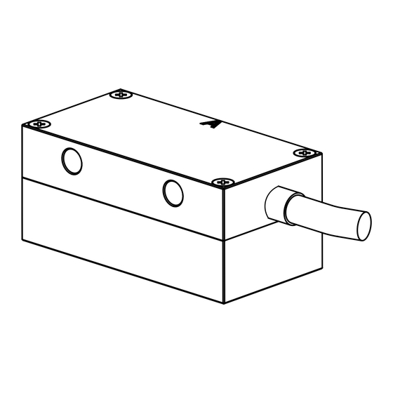
- Seite 5 Abtastkopf / Scanning head Technische Daten - Abtastkopf / Technical data - scanning head LMKA-1110x / LMKA-2110x Arbeitstemperatur: -10°C … 85°C Operating temperature: Lagertemperatur: -20°C … 85°C Storage temperature: Schutzart: Ip67 Protection class: Vibration: < 200 m/s² für (for) 55 – 2000 Hz Vibration: Schock: <...
-
Seite 6: Mögliche Auflösungen Für 1Vss Ausgang
Mögliche Auflösungen für 1Vss Ausgang Possible resolutions for 1Vpp output Ausgangsfrequenz fa (eingangs- Ausgangs Signal / Output signal frequenz für Folgeelektronik) ist für Sinus 1Vss / Sine 1Vpp 1Vss-Systeme auf 300kHz begrenzt. signal Perioden Max. Stromverbrauch signal periods output frequency fa (input frequency geschwindigkeit for subsequent electronics) is limited perioden... - Seite 7 Montagezeichnungen Abtastkopf LMKA-1110x / 2110x Assembly drawing scanning head LMKA-1110x / 2110x Maßband Typ LMBA-1110 / 2110 Scale type LMBA-1110 / 2110 Messkopf Measuring head 2 x 4,5 Absolutspurseite Zählrichtung Absolut track side Count direction Maßband Scale 0,1/1000 LMKA-1110 / 2110...
- Seite 8 Montagezeichnungen Abtastkopf LMKA-1110x / 2110x Assembly drawing scanning head LMKA-1110x / 2110x Maßband Typ LMBA-1410 / 2410 Für die Montage von LMbA-1410 / 2410 gibt es eine eigene Montageanleitung Scale type LMBA-1410 / 2410 For mounting the lmbA-1410 / 2410 there is a separate mounting assembly available ±0,5 Zylinderschrauben M4x6 0,05/1000...
-
Seite 9: Montage
Montage Mounting Montageart des Maßbandes mittels Einlegenut Mounting measuring tape with the aid of the mounting groove Untergrund: feingefräst, fettfrei (gereinigt mit z.b. Alkohol, Aceton,...) Montagevorbereitung: Montagenut vorsehen - Idealerweise im gleichen Aufspann wie für die Vorbereitung der Führungsschienen - Anschlagschulter notwendige Fräsarbeit Base: precision-milled, free of grease (cleaned with alcohol, acetone,...) Preparation: Prepare mounting groove - ideally in the same operation as... - Seite 10 Montagenut bzw Montageschulter für Maßband auf Parallelität prüfen Check parallel alignment of mounting groove or mounting shoulder for measuring tape Mittels Messuhr die Höhendifferenz +/- 0,1 mm der einlegenut prüfen Use a dial gauge to check the height tolerance of +/- 0,1 mm for the mounting groove Überprüfung der parallelität von 0,2 mm in Verfahrensrichtung Check the parallel alignment of 0.2 mm in traverse direction...
- Seite 11 Montageart des Maßbandes mittels Hilfslineal Mounting the measuring tape by means of straight edge Untergrund: feingefräst, fettfrei (gereinigt mit z.b. Alkohol, Aceton,...) Base: precision-milled, free of grease (cleaned with alcohol, acetone,...) einstellung der parallelität des Hilfslineals von 0,2 mm Mittels Messuhr die Höhentoleranz +/- 0,1 mm der in Verfahrensrichtung Montagefläche prüfen set parallel alignment of straight edge of 0.2mm in Use dial gauge to check the height tolerance of +/- 0,1...
- Seite 12 Montage des Maßbandes LMBA-1110 / 2110 Mounting measuring tape LMBA-1110 / 2110 Das band darf nicht mit einem Radius < 300 mm gehoben werden. Während des ganzen Montageverfahrens darauf achten, dass keine Knickpunkte entstehen. Montagefläche prüfen und mit größter Sorgfalt vorbereiten. The measuring tape must be not bended with a radius < 300 mm. Take particular care that no bends or kinks occur du- ring the entire mounting procedure. Check the mounting surface and prepare with the utmost care.
-
Seite 13: Montage Des Abtastkopfes
Montage des Abtastkopfes Mounting the scanning head Richtig! Falsch! Right! Wrong! Die Referenzmarkierungen am Maßband und Abtastkopf müssen auf der gleichen Seite sein. The reference marks on the measuring tape and scanning head must be on the same side. LMKA-1110 / 2110... - Seite 14 Montage des Abtastkopfes LMKA-1110 / 2110 Mounting scanning head LMKA-1110 / 2110 Idealerweise wird ein Montagewinkel mit Langlöchern verwendet um die paralle- le Ausrichtung des Abtastkopfes in Messrichtung zu vereinfachen. Dieser muss auf 0,1 mm parallelität zum montierten Maßband ausgerichtet werden. A mounting bracket with slots should be ideally used to simplify parallel align- ment of the scanning head in measurement direction.
- Seite 15 Der Messabstand zwischen Abtastkopf und Maßband wird mittels der mitgelieferten Abstandsfolie eingestellt indem diese zwischen beide Komponenten gelegt wird. Der Abtastkopf wird leicht in pfeilrichtung angedrückt und mittels 2 Stk. M4 Innensechskant- Schrauben befestigt (1,2 Nm Anzugsmoment) und die Folie entfernt. Zur Kontrolle wird vorsichtig an mehreren Stellen der Messstrecke angehalten und der Abstand mittels der Abstandsfolie überprüft indem diese zwischen die beiden Komponenten geschoben wird.
-
Seite 16: Versorgungspannung
Versorgungspannung Power supply Zulässige Versorgungsspannung 5 V ±5 % Allowed supply voltage: 5V ±5 % Welligkeit niederfrequent: < 100mVss Ripple, low frequency: < 100mVss Störsignal hochfrequent: < 250mV bei du/dt>5V/µs Disturbing signal, high frequency: < 250mV at dU/dt>5V/µs Schirmkonzept Shielding concept CNC - Controller Abstand zu Störquelle > 100mm Distance to noise sources > 100mm Schirm auf Gehäuse bei allen Steckern Shield on housing at all connectors... - Seite 17 Kabel Cable Technische Daten Technical data Kabel für Messsystem Verlängerungskabel-VK Cable for measuring system Extension cable-VK Mantel: PUR, hochflexibel, schleppkettentauglich Jacket: PUR, high flexible, suitable for energy chains Durchmesser: 5,3mm ~ 8mm Diameter: Adern: 5 (2 x 0,05) + 1 ( 2 x 0,14) mm 4 (2 x 0,14) + 2( 2 x 0,5) mm Wires: Biegeradius: Bending radius:...
-
Seite 18: Steckerbelegung Plug And Connection Assignments
Steckerbelegung Plug and connection assignments 17 pol. CONNEI- Kupplung (Stift) 17 pin CONNEI coupling (male) Spannungsversorgung Inkrementalsignale Absolut Schnittstelle Power supply incremental signals Absolute interface Signal 5V-Sensor 0V-Sensor Data+ Data- Clock+ Clock- Farbe rot-weiß blau blau-weiß grün gelb braun weiß violett schwarz rosa... - Seite 19 Notizen Notes LMKA-1110 / 2110...
- Seite 20 änderungen kommen, werden diese unverzüglich in den www.amo-gmbh.com. Dokumenten auf unserer Homepage www.amo-gmbh.com aktualisert. With the publication of this mounting instruction all previous editions Mit erscheinen dieser Montageanleitung verlieren alle vorherigen Ausga- become invalid.