
Verwandte Anleitungen für AMO AMOSIN MHS


Inhaltszusammenfassung für AMO AMOSIN MHS
- Seite 1 AMO GmbH AMOSIN ® Induktives Winkelmesssystem Inductive Angle Measuring System Montageanleitung Installation and Mounting Instructions MA_MHS_CHS_20140917 MHS / CHS...
-
Seite 2: Allgemein
Warranty: AMO Automatisierung Messtechnik Optik GmbH gewährt auf die Komponenten der AMO Automatisierung Messtechnik Optik GmbH shall grant a warranty period of 24 months from Winkelmesssysteme MHS / CHS eine Gewährleistungszeit von 24 Monaten ab Lieferdatum. Bei the date of delivery on the components of the MHS / CHS angle measuring systems. Incorrect falscher Bedienung oder Montage, unzureichender oder falscher elektrischer Anschlüsse, Betrieb... - Seite 3 CHS korrigierte Positionswerte am Ausgang zur Verfügung. CHS provides a corrected position signal at the output. Detaillierte techn. Daten zu MHS und CHS entnehmen Sie bitte Detailed technical information to MHS and CHS please see the dem Produktkatalog auf www.amo-gmbh.com. brochures on www.amo-gmbh.com. MHS / CHS...
- Seite 4 Lieferumfang MHS Items supplied MHS 1. Messflansch WMF oder Messring WMR Measuring flange WMF or measuring ring WMR 2. Abtastköpfe WMK-100/1050/300 Reading heads WMK-100/1050/300 3. MHS – Auswerteelektronik MHS – evaluation electronics 4. Abstandsfolie Spacer film 5. Montageanleitung MHS/CHS und WMI-100/1050/300 Mounting instructions MHS/CHS and WMI-100/1050/300 6.
-
Seite 5: Abmessungen Mhs - Auswerteelektronik
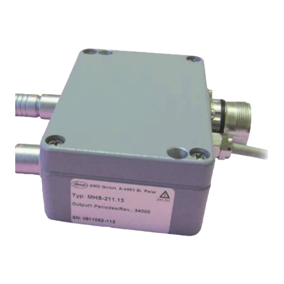
Abmessungen MHS – Auswerteelektronik Dimensions MHS – evaluation electronics Abtastkopf E1 Abtastkopf E2 Measuring Head E1 Measuring Head E2 Montagebohrungen, Durchmesser 5mm Mounting holes,diameter 5mm Spannungsversorgung Ausgang Messsystem Power supply System Output Die Abmessungen der Abtastköpfe entnehmen Sie bitte dem Katalog „Winkelmesssysteme nach dem AMOSIN Messprinzip“ For the dimensions of the reading heads please refer to our brochure „Angle measuring systems according to the AMOSIN measuring principle“... - Seite 6 Ist wie in beiliegender Montageanleitung opposite position has to be done as described in the enclosed WMI (siehe www.amo-gmbh.com) beschrieben durchzuführen. mounting instruction WMI. System now is ready for operation.
- Seite 7 Lieferumfang CHS Items supplied CHS 1. Messflansch WMF oder Messring WMR Measuring flange WMF or measuring ring WMR 2. Abtastkopf WMK-100/1050/300 Reading head WMK-100/1050/300 3. CHS – Auswerteelektronik CHS – evaluation electronics 4. Kalibriereinheit WKE (in Verbindung mit Kalibrierkopf) Calibration unit WKE (together with calibration head) 5.
-
Seite 8: Abmessungen Chs - Auswerteelektronik
Abmessungen CHS – Auswerteelektronik Dimensions CHS – evaluation electronics WKE - Kalibriereinheit Abtastkopf E1 WKE - calibration Unit measuring head E1 Montagebohrungen, Durchmesser 5mm Mounting holes,diameter 5mm Spannungsversorgung Ausgang Messsystem Power Supply System output Die Abmessungen der Abtastköpfe entnehmen Sie bitte dem Katalog „Winkelmesssysteme nach dem AMOSINMessprinzip“ For the dimensions of the reading heads please refer to our brochure „Angle measuring systems according to the AMOSIN measuring principle“... -
Seite 9: Montage- Und Kalibriervorgang Chs
Montage- und Kalibriervorgang CHS mounting and calibration procedure CHS 1.mounting of WMF respectively WMR and reading 1. Montage des WMF bzw. WMR und des Abtastkop- head WMK fes WMK Die Montage des Messflansches WMF bzw. Messringes WMR, The assembly of the measuring flange WMF respectively the sowie des Abtastkopfes sind wie in beiliegender measuring ring and the reading head has to be done as Montageanleitung WMI beschrieben durchzuführen. -
Seite 10: Montage Der Winkelkalibriereinheit Wke
2. Montage der Winkelkalibriereinheit WKE 2. Mounting of Angle Calibration Unit WKE Die Winkelkalibriereinheit WKE mittels beiliegendem Adapterka- Connect the calibration unit WKE to the input „Input WKE“ on bel an den Eingang “Input WKE” an der CHS anschließen. the CHS by using the adapter cable Der Kalibrierkopf ist wie in der Montageanleitung WMI beschrie- Mount the calibration head on the calibration positions as de- ben an den jeweiligen Kalibrierpositionen zu montieren. - Seite 11 Während des Kalibriervorgangs arbeitet das Messsystem nor- The measuring system is working properly during the calibration mal, d.h. die Ausgangssignale der CHS werden nicht procedure, i.e. the output signals of the CHS are not beeinflußt. influenced. Die Kalibrierposition wird über den Programmschalter an der The calibration procedure will be selected with the “program WKE eingestellt.
-
Seite 12: Beschreibung
Programmierschalter Status – LED Program switch State - LED Betriebsart Status LED: Beschreibung PROG Mode of operation State LED: Description Normaler Betriebszustand Dunkel dark Standard operation mode Normaler Betriebszustand System ist bereit für Kalibriervor- Standard operation mode Blinkt langsam gang Flash slow System is ready for calibration procedure... - Seite 13 4. Kalibriervorgang / Detailliert 4. Calibration procedure / detailed Der Kalibriervorgang ist für alle Kalibrierpositionen, beginnend The calibration procedure is the same for all calibration posi- bei CAL_POS_1 in gleicher Weise durchzuführen: tions starting at CAL_POS_1: • Spannungsversorgung ausschalten • Power Off •...
-
Seite 14: Fehlerbehandlung
5. Fehlerbehandlung 5. Error handling Ein Fehler während des Kalibriervorganges wird durch die An error during the calibration procedure is indicatet by the kontinuierlich hell leuchtende LED angezeigt. continously bright lighting LED. Der Fehler kann durch Power_Off/On quittiert werden. The error can be cancelled by performing a Power_Off/On. Fehlerbeschreibung Fehlerursache Error description... -
Seite 15: Beschreibung Der Ausgangssignale 1Vss
Beschreibung der Ausgangssignale 1Vss Description of the Output signals 1Vpp Empfohlene Beschaltung der Nachfolgeelektronik: Recommended circuit of the subsequent electronics: A+,B+,RI+ (und deren invertierte Signale) A+,B+,RI+ (and their invertierted Signals) direkte Signalausgabe Unterteilungsfaktor D = 1 direct signal output with dividing factor D = 1 A’+,B’+,RI’+ (und deren invertierte Signale) A’+,B’+,RI’+ (und deren invertierte Signale) unterteilte Signalausgabe, Unterteilungsfaktor D ≠... - Seite 16 Signal Diagramm: signal diagram:...
-
Seite 17: Beschreibung Der Ausgangssignale Ttl - Rs422
Beschreibung der Ausgangssignale TTL - RS422 Description of the output signals TTL - RS422 Empfohlene Beschaltung der Nachfolgeelektronik: Signal Diagramm: Recommended circuit of the subsequent electronics: Signal diagram: MHS / CHS... -
Seite 18: Stecker Und Anschlussbelegungen Für Systemausgang Mhs / Chs
Stecker und Anschlussbelegungen für Systemausgang MHS / CHS Plug and connection assignements for system output MHS / CHS Connei Kupplung 12-polig, Stift-Kontakte CONNEI connector coupling 12-pin Signals Sensor Sensor blue red/ Color white pink grey green yellow brown blue blue/ white white Connections... - Seite 19 Notizen Notice MHS / CHS...
- Seite 20 Änderungen kommen, werden diese unverzüglich in den Dokumen- www.amo-gmbh.com. ten auf unserer Homepage www.amo-gmbh.com aktualisert. With the publication of this mounting instruction all previous editions be- Mit Erscheinen dieser Montageanleitung verlieren alle vorherigen Ausga- come invalid.