biohort StoreMax 190 Aufbauanleitung
Vorschau ausblenden
Andere Handbücher für StoreMax 190:
- Anleitung (16 Seiten) ,
- Aufbauanleitung (16 Seiten) ,
- Aufbauanleitung (16 Seiten)

Verwandte Anleitungen für biohort StoreMax 190


Inhaltszusammenfassung für biohort StoreMax 190
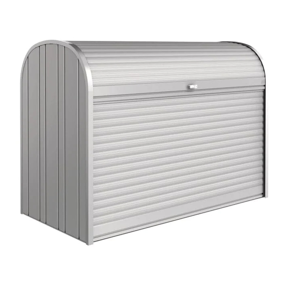
- Seite 1 „StoreMax 190“ Aufbauanleitung Assembly manual Instruction de montage Montage-instructies Istruzione di montaggio 190 cm x 97 cm x 136 cm BIOHORT Gartengeräte GmbH, A-4120 Neufelden www.biohort.at...
-
Seite 2: Care & Maintenance
• Ne pas assembler quand il y a du vent • Cette instruction de montage décrit l’assemblage d’un • Portez absolument des gants de travail pour le StoreMax 190. Valable par analogie pour les autres couleurs montage et le nettoyage et le laquage spécial •... -
Seite 3: Übersicht Teile
Ihres „StoreMax 190“ mit den beiliegenden Schrauben und Dübel. Denken Sie an Stürmböen!!! ATTENTION: Do not forget to have sufficient anchorage of your “StoreMax 190” using the enclosed screws and dowels. Consider heavy gusts of wind!!! ATTENTION: N’oubliez pas un ancrage suffisant de votre «StoreMax 190» à l’aide des vis et des chevilles jointes –... - Seite 4 Zusammenbauschritte Assembly steps - Etapes d’assemblage - Stappen van de montage Montage der Rückwand: Legen Sie die „A” Bodenplatte auf einen ebenen Untergrund. Stellen Sie die linke Rückwand wie abgebildet in das U-Profil an der Rückseite der Boden platte. Detail „A” Achten Sie auf die richtige Positionierung der Rück- wand: Innenseite = hellgraue Seite, Schlitz (siehe Foto) muss sich oben/außen befinden.
- Seite 5 Montage der Seitenwände: Stecken Sie die rechte Seitenwand in das U-Profil der rechten Seite der Bodenplatte. (Achtung: die rechte Seitenwand erkennen Sie daran, dass die Rollladen- Bremsfeder an der Vorderseite positioniert ist – siehe Pfeil). Verbinden Sie die rechte Seitenwand mit der Rückwand provisorisch (wie abgebildet) mit dem schwarzen Kunststoffteil (=Montagehilfe, welche spä- ter als Distanzstück für Bodenplatte/Rückwand dient).
- Seite 6 Side wall assembly: Stick the right side wall into the U-section on the right side of the bottom plate (you can identify the right side wall by the roller shutter-stopper positioned on the front side – see arrows). Link the right side wall and the rear wall using the black Feder plastic part (assembly help which will later serve as distance piece spring...
- Seite 7 Vorne links Vorne rechts hinten front side left front side right rear avant gauche avant droit l’envers hinten rear l’envers Einbau des Versteifungsprofils / Einbau der Distanzstücke: Nehmen Sie wie abgebildet das Versteifungsprofil, führen Sie es vorsichtig in die Box ein und verschrauben Sie es links und rechts an den Enden (siehe Pfeile) handfest nur mit je einer Schraube/Scheibe/Mutter an den Seitenwänden.
- Seite 8 Fixation du profil de renforcement et des pièces de distance: Prenez comme représenté le profil de renforcement et positionnez-le à l’intérieur du Store Max. Fixez les parois latérales et le profil de renforcement sur les côtés droit et gauche (voir flèches) avec une vis/rondelle/écrou. Tournez le profil de renforcement en arrière et en haut et reliez-le et la paroi arrière à...
- Seite 9 Skizze Schnurführung Section string guiding Dessin passage de la ficelle part into the stiffening section. Verriegelung rechts Put the white nylon string over the pulley locking right and leave the end of the string protrude at verrouillage droit the back. Fix the locking pins at the front left and right side of the stiffener section using two screws, washers and nuts for each pin.
- Seite 10 Einführen der Rollläden: Legen Sie die Box vorsichtig nach vorne. Führen Sie den „vor- deren“ Rollladen (=ohne Schloss!) mit der Außenseite nach oben und mit den weißen Gum- mipuffern voran (siehe Foto) behutsam in die innere (=untere) Führungsnut des Aluminiumbo gens ein. Achten Sie dabei darauf, dass die seitlichen, schwar- zen Kunststoffgleitrollen der Alumini um la mellen nicht verspießen.
- Seite 11 Die Gummi-Stopper werden ebenfalls links und rechts mit je einer kurzen Niro-Schraube gesichert. Jetzt stellen Sie Ihren „StoreMax 190“ wieder auf. Assembly of the back roller shutter-stoppers: Put both spring-stop- pers onto the inner grooves as illustrated and push them down as far as possible.
- Seite 12 On the back side insert the white nylon string into the hole of the slat furthest back and make a tight knot on the place marked in red. Place your “StoreMax 190” horizontally and orthogonally on an even ground and check the smooth running of the roller shutter.
- Seite 13 Check the operation of the cylinder locks and locking pin. Oil the cylinder lock at least once a year with a thin, liquid oil. Contrôle de fonctionnalité et finissage: Le StoreMax 190 est fer- mé. Enfilez la ficelle en nylon à travers le trou de la dernière lamelle comme représenté...
-
Seite 16: Zubehör Für Den Storemax 190
Zubehör für den StoreMax 190 Optional accessory for StoreMax 190 Accessoire optionnel pour StoreMax 190 ohne Dekoration without decoration sans décoration Regaleset inkl. 2 Regalsteher (Art.-Nr. 74020) Zwischenboden inkl. 8 Stützen, auch als 2-teiliges Shelf-bases incl. 2 shelf sections (order-no: 74020) Regal verwendbar (Art.-Nr.