Inhaltsverzeichnis

Verwandte Anleitungen für Stel MIGGY 171


Inhaltszusammenfassung für Stel MIGGY 171
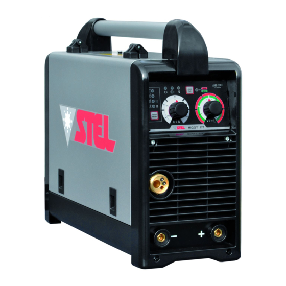
- Seite 1 6918900030 - MANUALE DI ISTRUZIONE PER SALDATRICE - INSTRUCTION MANUAL FOR WELDING MACHINE - BETRIEBSANLEITUNG FÜR SCHWEIßERÄTE MIGGY 171 MIGGY 171 MIGGY 171 MIGGY 171 Info : www.stelgroup.it - tel. +39 0444 639525...
- Seite 2 The EMC Directive 2004/108/EC The RoHS Directive 2011/65/EU Type of equipment MMA Welding Equipment Type of designation 601074000L – Miggy 171 Brand name or trade mark STEL Manufacturer or his authorized representatives established within the EEA: Name, address, phone, website: STEL s.r.l...
- Seite 3 6918900030 SICUREZZE WARNING LO SHOCK ELETTRICO PUÒ UCCIDERE Disconnettere macchina dalla rete alimentazione prima di intervenire sul generatore. - Non lavorare con i rivestimenti dei cavi deteriorati. - Non toccare le parti elettriche scoperte. - Assicurarsi che tutti i pannelli di copertura del generatore di corrente siano ben fissati al loro posto quando la macchina è...
-
Seite 4: Descrizione Generale
È vietato l’utilizzo e apparecchiature spedite da STEL sono state l’avvicinamento alla macchina da parte di persone sottoposte ad un rigoroso controllo di qualità. Tuttavia portatori di stimolatori elettrici (PACE MAKERS). se la Vs. apparecchiatura non dovesse funzionare correttamente, rivolgetevi al Vs. -
Seite 5: Installazione
Non mettere in funzione o spostare il generatore causa di disturbi condotti e irradiati. nel caso si trovi in posizione precaria. Il generatore MIGGY 171 non rispetta i limiti della Non posizionare il generatore su piani inclinati IEC 61000-3-12. superiori a 10°. - Seite 6 6918900030 fare al filo meno curve possibile. Inserire la spina in DISPOSIZIONE una presa di corrente adeguata. Chiudere il rullo SALDATURA TIG pressore, accendere macchina portando l’interruttore di linea in posizione “ON”, premere il Rispettare indicazioni fornite pulsante avanzamento filo per far girare il motore precedentemente a riguardo dell’allacciamento del traino fino alla fuoriuscita del filo dalla torcia primario e dell’installazione.
-
Seite 7: Descrizione Pannello Frontale
6918900030 DISPOSIZIONE DESCRIZIONE PANNELLO SALDATURA MIG SINERGICO FRONTALE Rispettare indicazioni fornite precedentemente a riguardo dell’ allacciamento primario e dell’installazione. 2) La macchina è predisposta anche per la saldatura in modalità MIG sinergico con filo acciaio/carbonio da 0.6 e 0.8. 3) Per impostare la saldatura in modalità sinergica premere il pulsante AUTO SET n.4, il led selezione modalità... - Seite 8 6918900030 SMALTIMENTO DUTY CYCLE E APPARECCHIATURE SOVRATEMPERATURA Il ciclo di intermittenza è la percentuale di utilizzo ELETTRICHE ED della saldatrice su 10 minuti che l’ operatore deve ELETTRONICHE rispettare per evitare che scatti il blocco di erogazione per sovratemperatura. Non smaltire le apparecchiature Se la macchina entra in sovratemperatura: elettriche assieme ai rifiuti normali! giallo...
- Seite 9 6918900030 must be free from damage to the insulation. BARE SAFETY CABLES ARE DANGEROUS. Do not use the ELECTRIC SHOCK CAN KILL machine if the power cable is damaged; it must be - Disconnect the power supply before working on replaced immediately.
-
Seite 10: General Characteristics
Complaints for faulty goods: All the equipment inflammable gases or combustible vapours. shipped by STEL is subjected to strict quality control. However, if your equipment does not work GENERAL properly, consult your authorised dealer. CHARACTERISTICS TECHNICAL DATA... -
Seite 11: Installation
MAINS VOLTAGE The machine operates from a mains voltages differing by +/-20% from the rated mains value (example: 230V rated, Minimum voltage 184V, maximum voltage 276V). Miggy 171 Fuse 16A CONNECTION - Before making the electrical connections between the welding machine and the line switch, ensure... - Seite 12 6918900030 the least possible number of curves . PREPARING FOR WELDING 10) Insert the plug in a suitable power socket. (TIG 11) Close the pressing roller, switch on the machine turning the line switch to “ON” position, 1) Respect the indications given previously press the wire advance button to make the feeding concerning primary connection and installation.
-
Seite 13: Front Panel Description
6918900030 Green for 0,8mm wire. FRONT PANEL DESCRIPTION 5) Wire feed speed can be adjusted by regulating Potentiometer 12. An increase or decrease wire speed rate of + 20% or - 20% of selected Synergic is regulated from Potentiometer 13. 6) To go out of Synergic MIG mode and return to Manual MIG, press selection button 15., and hold continuously until the light 14. -
Seite 14: Disposal Of Electrical And Electronic Equipment
6918900030 DISPOSAL OF ELECTRICAL DUTY CYCLE AND AND ELECTRONIC EXCESSES TEMPERATURE The duty cycle is the percentage of use of the EQUIPMENT welding machine within 10 minutes which the dispose electrical operator must respect to avoid the machine equipment together with normal blocking output temperature... -
Seite 15: Sicherheitsvorschriften
6918900030 VORSICHTSMASSNAHMEN UM EINEN SICHERHEITSVORSCHRIFTEN ELEKTROSCHOCK ZU VERHINDERN EIN ELEKTROSCHOCK KANN TÖDLICH SEIN Treffen Sie folgende Vorkehrungen, wenn Sie mit - Vor Arbeiten am Gerät, Netzstecker ziehen einem Schweißgerät arbeiten: - Verwenden Sie keine beschädigten Kabel und - Halten Sie sich und Ihre Kleidung sauber. Leitungen - Berühren Sie keine feuchten oder nassen Teile, - Berühren Sie keine unter Spannung stehenden... -
Seite 16: Allgemeine Eigenschaften
- Verwenden Sie nicht das Gerät in Bereichen mit Reklamation fehlerhafter Ware: Sämtliche hoher Konzentration an Stäuben, entflammbaren Geräte, welche von STEL versendet werden, Gasen und brennbaren Dämpfen. unterliegen einer strengen Qualitätskontrolle. Sollte jedoch Ihr Gerät nicht einwandfrei funktionieren, ALLGEMEINE nehmen Sie bitte Kontakt zu Ihrem autorisierten EIGENSCHAFTEN Händler auf. -
Seite 17: Elektrische Merkmale
Das Gerät arbeitet mit einem Toleranzbereich von Schweißgerätetyp 20% der Nennspannung (Beispiel: Nennspannung Identifikation mit Verweis auf die Seriennummer 230V, Mindestspannung 184V, Höchstspannung Symbol des Typs des Schweißgeräts 276V).Miggy 171 Sicherung 16A Verweis auf Bau Norm ANSCHLUSS b) SCHWEISSLEISTUNG - Bevor Sie den elektrischen Anschluss zwischen Symbol für den Arbeitsprozess... -
Seite 18: Aneitung Zum Wig- Schweissen
6918900030 ERDUNG ANEITUNG ZUM WIG- - Um den Anwenderschutz sicher zu stellen, muss Gerät korrekt Erdungsanlage SCHWEISSEN angeschlossen werden. 1) Sich an die vorab gegebenen Anleitungen (INTERNATIONALE SICHERHEITSVORSCHRIFTEN) betreffend Primäranschluss - Um Entladungen bei versehentlichem Kontakt mit Installation halten. geerdeten Objekten vermeiden, 2) Das Massekabel an die positive Buchse des... -
Seite 19: Anleitungen Zum Mig- Schweissen Ohne Gas
6918900030 ist, eine anderes Drahtmaß einzusetzen). Bei Umsteigen auf einen anderen Drahtquerschnitt ANLEITUNG ZUM muss Folgendes gewechselt werden: Rollen und SYNERGETISCHEN MIG- stromführendes Rohr (es handelt sich dabei um das Endteils des Brenners, aus dem der Draht SCHWEISSEN vorsteht). zuvor angeführten Anweisungen 8) Das äußere Ende des Brenners (Düse) und Primäranschluss und Installation befolgen. -
Seite 20: Beschreibung Der Frontblende
6918900030 des Gases aus dem Brenner einfach ignorieren. BESCHREIBUNG DER ENTSORGUNG VON FRONTBLENDE ELEKTRISCHEN UND ELEKTRONISCHEN GERÄTEN Entsorgen Sie keine elektrischen Geräte zusammen mit normalem Müll. Gemäß Europäischer Richtlinie 2002/96/EG über Elektro- Elektronik- Altgeräte Umsetzung in nationales Recht, müssen verbrauchte Elektro- und Elektronikgeräte getrennt gesammelt und einer umweltgerechten Wiederverwertung... -
Seite 21: Wiring Diagram
6918900030 WIRING DIAGRAM... -
Seite 22: Exploded View
6918900030 EXPLODED VIEW EXPLODED VIEW WIRE FEEDER (N.56) 664620000 631860000 6348100000... -
Seite 23: Spare Parts List
6918900030 SPARE PARTS LIST... - Seite 24 6918900030 N° DESCRIPTION CODE Instrumental Support 6203670T Instrumental Plate 66089700 Instruments panel protection 66077700 Fixed Socket 64280000 Knob d.29 66079800 Front panel 6607510C Fixed sockets support 620365BS Logic pcb 61235500 Motor Wire Feeder 64239000 Resistance 65030400 Screw Copper Connection 62039500 Inverter Support 6203710T Base...
- Seite 25 6918900030 FRONT CONNECTIONS TYPE CONNECTION DECSRIPTION EARTH CLAMP NEGATIVE ELECTRODE POSITIVE TYPE CONNECTION DECSRIPTION TIG TORCH NEGATIVE LIFT EARTH CLAMP POSITIVE TYPE CONNECTION DECSRIPTION MIG TORCH POSITIVE EARTH CLAMP NEGATIVE...
- Seite 26 6918900030...
- Seite 27 6918900030 Info : www.stelgroup.it - tel. +39 0444 639525...