HomeMatic RS485 Bedienungsanleitung
Rs485 lan gateway,
hutschienenmontage
Vorschau ausblenden
Andere Handbücher für RS485:
- Installationsanleitung (36 Seiten) ,
- Installationsanleitung (21 Seiten) ,
- Installations- und bedienungsanleitung (20 Seiten)

Verwandte Anleitungen für HomeMatic RS485


Inhaltszusammenfassung für HomeMatic RS485
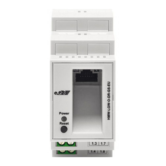
- Seite 1 Installations- und Bedienungsanleitung (S. 2) Installation and operating manual (p. 30) RS485 LAN Gateway, Hutschienenmontage RS485 LAN Gateway, for mounting on DIN rails HMW-LGW-O-DR-GS-EU...
- Seite 2 Dokumentation © 2013 eQ-3 AG, Deutschland Alle Rechte vorbehalten. Ohne schriftliche Zustim- mung des Herausgebers darf dieses Handbuch auch nicht auszugsweise in irgendeiner Form reproduziert werden oder unter Verwendung elektronischer, mecha- nischer oder chemischer Verfahren vervielfältigt oder verarbeitet werden. Es ist möglich, dass das vorliegende Handbuch noch drucktechnische Mängel oder Druckfehler aufweist.
-
Seite 3: Inhaltsverzeichnis
Funktion ......6 Allgemeine Systeminformation zu Homematic. 9 Allgemeine Hinweise zum Bussystem ..10 Allgemeine Hinweise zur Installation . -
Seite 4: Hinweise Zu Dieser Anleitung
Hinweise zu dieser Anleitung Lesen Sie diese Anleitung sorgfältig, bevor Sie Ihre Homematic Komponenten in Betrieb nehmen. Bewah- ren Sie die Anleitung zum späteren Nachschlagen auf! Wenn Sie das Gerät anderen Personen zur Nutzung überlassen, übergeben Sie auch diese Bedienungs- anleitung. - Seite 5 VDE 0100) erfolgen. Dabei sind die geltenden Unfallverhütungsvorschriften zu beachten. Zur Vermeidung eines elektrischen Schlages schalten Sie vor Arbeiten am Gerät die Netz- spannung frei (Sicherungsautomat abschal- ten). Bei Nichtbeachtung der Installationshinweise können Brand oder andere Gefahren entste- hen (siehe Abschnitt 6). Betreiben Sie das Gerät nur in Innenräumen und vermeiden Sie den Einfluss von Feuchtig- keit, Staub sowie Sonnen- oder andere Wär-...
-
Seite 6: Funktion
Beachten Sie die Installationsvorschriften für Installationen in Verteilersystemen (DIN VDE 0100-410). Funktion Das Homematic RS485 Gateway ermöglicht die Kom- munikation zwischen Homematic Wired-Geräten und der Homematic Zentrale CCU2. Die Verbindung zur Zentrale wird per Ethernet hergestellt. Die Kommuni- kation zu den angeschlossenen Geräten erfolgt über... - Seite 7 Übersicht Power Reset +24 V Power-LED Reset-Taste Ethernet-Buchse Bus A Bus B Spannungsversorgung (+24 V) Masse (GND)
- Seite 8 Das Gerät wird komfortabel auf einer Standard- Hutschiene in einer Elektroverteilung montiert. Durch Anlernen des Homematic RS485 Gateways an die Homematic Zentrale kann das Homematic Wired System flexibel von überall im Haus gesteuert werden. Die Kommunikation zwischen dem Gateway und der Zentrale ist über die im Haus bauseits vorhandene...
-
Seite 9: Allgemeine Systeminformation Zu Homematic
Internet Info CCU2 Allgemeine Systeminformation zu Homematic Dieses Gerät ist Teil des Homematic Smart-Home- Systems. Alle im System installierten Geräte werden mit einer Standardkonfiguration ausgeliefert. Darüber hinaus ist die Funktion der Geräte über ein Pro- grammiergerät und Software konfigurierbar. Welcher... -
Seite 10: Allgemeine Hinweise Zum Bussystem
Allgemeine Hinweise zum Bus- system 5.1 Allgemeine Hinweise zur Installation Beim Anschluss des RS485-Busses sind die A-Klem- men (1.3), die B-Klemmen (1.7), die 24 V Spannungs- versorgung (1.4) und die Masseklemme (1.8) der Module einer Unterverteilung (max. 127 Stück) jeweils miteinander zu verbinden. -
Seite 11: Installation
Die Stromversorgung erfolgt über ein 24V-Hut- schienen-Netzteil (24 V Netzteil mit stabilisierter Ausgangsspannung) entsprechend der Anzahl und Gesamtstromaufnahme aller vorhandenen Module in der jeweiligen Unterverteilung dimensioniert. Bitte entnehmen Sie die Daten der Leistungsaufnahme für einzelne Geräte der jeweiligen Bedienungsanleitung. Installation Beachten Sie die Installationsvorschriften für das Errichten von Niederspannungsanlagen gemäß... - Seite 12 - Erden und Kurzschließen; - benachbarte, unter Spannung stehende Teile abdecken oder abschranken; • Auswahl des geeigneten Werkzeuges, der Messge- räte und ggf. der persönlichen Schutzausrüstung; • Auswertung der Messergebnisse; • Auswahl des Elektro-Installationsmaterials zur Sicherstellung der Abschaltbedingungen; • IP-Schutzarten; •...
- Seite 13 Technischen Anschlussbe- stimmungen (TAB) des Energieversorgers zu berücksichtigen. Zur Installation gehen Sie wie folgt vor: • Setzen Sie das Homematic RS485 Gateway oben mit den Rastnasen auf die Hutschiene auf. • Verrasten Sie das Gerät, indem Sie es nach unten...
- Seite 14 drücken. • Achten Sie darauf, dass die Rastnasen komplett einrasten und das Gerät fest auf der Schiene sitzt. • Isolieren Sie die Drahtenden der Leitung zum Netz- teil und der Busleitung auf eine Länge von 8 mm ab, ohne dabei die blanke Ader zu verletzen. Beachten Sie die zugelassenen Leitungsquerschnitte: flexible Leitung mit starre Leitung [mm...
- Seite 15 Innerhalb einer Unterverteilung dürfen HMW- Leitungen (24V-DC und RS485-BUS) als unge- schirmte Leitungen ausgeführt und max. 3 m lang sein. Power Reset +24 V • Schließen Sie das Homematic RS485 Gateway mit dem RS485-BUS an die Klemmen 1.3 (A) und 1.7 (B) an.
- Seite 16 Power Reset +24 V • Stecken Sie das beiliegende Ethernet-Kabel in die dafür vorgesehene Buchse (C). Power Reset +24 V Um eine sichere Bedienung des Gerätes ge- währleisten zu können, wird ein Ethernetkabel mit mindestens der Kategorie 5 (CAT5 FTP) benötigt.
-
Seite 17: Installationshinweise Bei Abgesetzten Komponenten
Busabschluss Widerstandes ist zwingend erforderlich. 6.1 Installationshinweise bei abgesetzten Komponenten Wenn Sie Homematic Wired Geräte in einer Unterver- teilung absetzen (Leitungslänge des RS485-Bus und der 24V-DC-Leitung > 3 m), müssen Sie eine beson- dere Installation beachten: Sobald die Leitungen RS485-Bus und 24V-DC die Unterverteilung verlassen (Leitungen län-... - Seite 18 Kurzschlüssen zu sichern oder so weit zu kürzen, dass diese mit der Isolierung des Kabels abschließen. Der zur Schirmung parallel geführte Draht (Beidraht bzw. Drain wire, s. nachfolgende Abbildung) ist dazu an den GND-Anschluss des Homematic Wired Ge- rätes anzuschließen. Schirm Mantel Beidraht...
-
Seite 19: Anschlussbeispiel Mit Einer Unterverteilung
6.2 Anschlussbeispiel mit einer Unterverteilung Hauptverteilung Unterverteilung LAN Gateway Aktor Prog. +24 V +24 V Beidraht Beidraht (aufgelegt) (nicht aufgelegt) geschirmte Leitung Bei mehreren Unterverteilungen sollten Sie den Schirm jeweils in jeder Unterverteilung wieder neu auflegen. D.h.: Schirm • ankommende geschirmte Leitung nicht auflegen •... -
Seite 20: Anschlussbeispiel Mit Mehreren Unter- Verteilungen
6.3 Anschlussbeispiel mit mehreren Unter- verteilungen... -
Seite 21: Anschluss- Und Installationsbeispiel
Sie dürfen den Schirm nicht mit dem Schutzlei- ter des Versorgungsnetzes verbinden. 6.4 Anschluss- und Installationsbeispiel +24V/SELV Klemme Funktion RS485-BUS, Leitung A Versorgungsspannung, +24 V RS485-BUS, Leitung B Versorgungsspannung, Masse (GND), Massebezug für alle Eingänge... -
Seite 22: Einbinden Ins Netzwerk (Lan)
Einbinden ins Netzwerk (LAN) Um eine Kommunikation zwischen Ihrer Homematic Zentrale und den Homematic Wired-Geräten herzu- stellen, muss das Homematic Wired RS485 Gateway ins Netzwerk eingebunden werden. Dazu gehen Sie bitte wie folgt vor: Einrichten über die Homematic Zentrale • Öffnen Sie die Bedienoberfläche WebUI in Ihrem Webbrowser. - Seite 23 Passwort (s. Aufkleber auf der Unterseite des Gateways) Ihres Homematic Wired RS485 Gateways ein. Diese können Sie später auch noch ändern. • Bestätigen Sie Ihre Eingaben mit „OK“ und klicken Sie im nächsten Fenster auf „Übernehmen“. • Starten Sie abschließend Ihre Homematic Zentrale neu.
-
Seite 24: Werkseinstellungen Des Gerätes Wieder- Herstellen
Um einzelne Homematic Wired Geräte in das System einbinden zu können, gehen Sie bitte wie in den dazugehörigen Bedienungsanlei- tungen beschrieben vor. Einzelheiten zu Netzwerkproblemen (z. B. kein DHCP) finden Sie im FAQ-Bereich auf der Website www.homematic.com Werkseinstellungen des Ge- rätes wiederherstellen... - Seite 25 > 6 s Power Reset +24 V • Lassen Sie die Taste los. • Drücken Sie die Taste erneut für ca. 3 Sekunden, bis die LED sehr langsam blinkt. > 3 s Power Reset +24 V • Lassen Sie die Taste los. •...
-
Seite 26: Deinstallation
Deinstallation • Zur Demontage des Homematic RS485 Gateways lösen Sie zunächst die Verdrahtungen. • Drücken Sie die Lasche an der unteren Rückseite des Gerätes mit einem Schlitzschraubendreher nach unten und nehmen Sie das Gerät mit einer Schwenkbewegung von der Hutschiene ab. -
Seite 27: Lieferumfang
11 Lieferumfang • Homematic RS485 LAN Gateway (montagefertig) • Ethernetkabel • Installations- und Bedienungsanleitung 12 Technische Daten Geräte-Kurzbezeichnung: HMW-LGW-O-DR-GS-EU Versorgungsspannung: 24 V /SELV Stromaufnahme: 100 mA (max.) Leistungsaufnahme im Ruhebetrieb: 0,75 W Schutzart: IP20 Umgebungstemperatur: 0 - 35 °C Gehäuseabmessungen:... - Seite 28 Entsorgungshinweis: Gerät nicht im Hausmüll entsorgen! Elektro- nische Geräte sind entsprechend der Richtli- nie über Elektro- und Elektronik-Altgeräte über die örtlichen Sammelstellen für Elektronik- Altgeräte zu entsorgen. Das CE-Zeichen ist ein Freiverkehrszeichen, das sich ausschließlich an die Behörden wendet und keine Zusicherung von Eigen- schaften beinhaltet.
- Seite 30 Documentation © 2013 eQ-3 AG, Germany All rights reserved. This manual may not be reprodu- ced in any format, either in whole or in part, nor may it be duplicated or edited by electronic, mechanical or chemical means, without the written consent of the publisher.
- Seite 31 Function ......34 General system information about Homematic 37 General information about the bus system . . . 38 General information on the installation.
-
Seite 32: Information About This Manual
Information about this manual Read this manual carefully before beginning operation with your Homematic components. Keep the manual handy for later consultation! If you hand over the de- vice to other persons for use, please hand over the operating manual as well. - Seite 33 prevention regulations must be complied with whilst such work is being carried out. Discon- nect the power to devices before working on them to prevent electrocution (switch circuit breaker). Ignoring installation instructions can cause fires or other hazards (see sec. 6). The device may only be operated indoors and must be protected from the effects of damp and dust, as well as solar or heat radiation.
-
Seite 34: Function
(DIN VDE 0100- 410). Function The Homematic RS485 Gateway enables commu- nication between Homematic Wired devices and the Homematic CCU2. Connection between Gateway and CCU2 is established via Ethernet. The communication to connected devices is established via the Homematic Wired Protocol. - Seite 35 Overview Power Reset +24 V Power LED Reset button Ethernet port Bus A Bus B Power supply (+24V)
- Seite 36 The device can be comfortably mounted on a DIN rail in an electrical distribution board. By teaching-in the Homematic RS485 Gateway to the Homematic Central Control Unit, the Homematic Wired system can be flexibly controlled from everywhere in the house. The...
-
Seite 37: General System Information About Homematic
Info CCU2 General system information about Homematic This device is a component of the Homematic Home Control System. All devices are delivered in a stan- dard configuration. The functionality of the device can also be configured with a programming device and software. -
Seite 38: General Information About The Bus System
General information about the bus system 5.1 General information on the installation When connecting the RS485 bus, the A terminals (1.3), the B terminals (1.7), the 24 V power supply and the ground terminal (1.8) of the modules of a sub- distribution (max. -
Seite 39: Installation
sumption of all existing modules. You will find further details regarding the power consumption of the single devices in the corresponding operating manual. Installation Observe the installation instructions for installa- tions in distribution systems (DIN VDE 0100- 410). Only to be installed by persons with the relevant electro-technical knowledge and experience. - Seite 40 • Selection of electrical installation material for safe- guarding shut-off conditions; • IP protection types; • Installation of electrical installation material; • Type of supply network (TN system, IT system, TT system) and the resulting connecting conditions (classical zero balancing, protective earthing, re- quired additional measures etc.).
- Seite 41 For installation, please proceed as follows: • Place the Homematic RS485 Gateway with the spring latch onto the DIN rail from above. • Latch the device on the DIN rail by pressing down.
- Seite 42 Observe the permissible cable cross sections. Flexible cable with fer- Rigid cable [mm2] rule [mm2] 0.14 – 2.50 0.14 – 1.5 • Wire the Homematic RS485 Gateway for the power supply with the power supply unit of terminal 1.4 (+24 V) and 1.8 (GND).
- Seite 43 3 m long. Make sure that the connections are made with correct polarity on the terminals. Power Reset +24 V • Then connect the Homematic RS485 Gateway to terminals 1.3 (A) and 1.7 (B) using the RS485 bus.
- Seite 44 Power Reset +24 V • Insert the supplied Ethernet cable into the corre- sponding socket (C). Power Reset +24 V To ensure secure operation of the device, an Ethernet cable of at least category 5 (CAT5 FTP) is required.
-
Seite 45: Installation Instructions For Remote Components
24 V DC cable > 3m), note the following installation requirements: As soon as the RS485 bus and 24 V DC ca- bles exit the sub-distribution board (cables longer than 3 m), a shielded cable must be used. - Seite 46 The wire routed in parallel with the shield (continuity wire, see figure below) must be connected to the GND socket of the Homematic wired device. Shield Jacket Drain wire...
-
Seite 47: Example Connection With One Sub-Distribution Board
6.2 Example connection with one sub-dis- tribution board Main distribution Sub-distribution LAN Gateway Actuator Prog. +24 V +24 V Drain wire Drain wire (connected) (not connected) Shielded cable If there is more than one sub-distribution board, you should make the shield connection separately in each of them, i.e.: •... -
Seite 48: Example Connection With More Than One Sub-Distribution Board
6.3 Example connection with more than one sub-distribution board... -
Seite 49: Connection And Installation Example
The shield must not be connected to the pro- tective conductor of the supply network. 6.4 Connection and installation example +24V/SELV Terminal Function RS485 Bus (Bus A) Supply voltage, +24 V RS485 Bus (Bus B) Supply voltage, ground (GND), ground reference for all inputs... -
Seite 50: Integration Into Network (Lan)
Integration into network (LAN) To establish communication between your Homema- tic Central Control Unit and the Homematic Wired devices, the Homematic RS485 Gateway has to be integrated into the network. To do this, proceed as follows: Configuration via Homematic Central Control Unit •... -
Seite 51: Restoring The Factory Settings
(e.g. no DHCP) can be found in the FAQs of the website www.homematic.com. Restoring the factory settings The factory settings of the Homematic RS485 Gate- way can be restored manually. If you do this, you will lose all your settings. - Seite 52 > 6 s Power Reset +24 V • Release the button. • Press the button again for approx. 3 seconds until the LED flashes very slowly. > 3 s Power Reset +24 V • Release the button. • The LED expires after a short time and the factory settings of the device will be restored.
-
Seite 53: Disassembly
Disassembly • Before disassembling the Homematic RS485 Gate- way, disconnect the wiring. • Press down the clip at the back of the device with a slotted screwdriver and remove the device from the rail. 10 Maintenance and cleaning The product does not require any maintenance. Re-... -
Seite 54: Scope Of Supply
11 Scope of supply • Homematic RS485 Gateway (ready for installation) • Ethernet cable • Installation and Operating Manual 12 Technical data Device short name: HMW-LGW-O-DR-GS-EU Power supply: 24 V /SELV Max. power consumption: 100 mA (max.) Standby power consumption: 0.75 W... - Seite 55 Instructions for disposal: Do not dispose of the device with regular domestic waste. Electronic equipment must be disposed of at local collection points for waste electronic equipment in compliance with the Waste Electrical and Electronic Equipment Directive. The CE sign is a free trading sign addressed exclusively to the authorities and does not include any warranty of any properties.
- Seite 56 Bevollmächtigter des Herstellers: Manufacturer’s authorised representative: eQ-3 AG Maiburger Straße 29 26789 Leer / GERMANY www.eQ-3.de...