
Verwandte Anleitungen für Epropulsion POD DRIVE EVO Serie


Inhaltszusammenfassung für Epropulsion POD DRIVE EVO Serie
- Seite 1 POD DRIVE EVO USER MANUAL BEDIENUNGSANLEITUNG POD DRIVE EVO Pod Drive 1.0 / Pod Drive 3.0 / Pod Drive 6.0 2021.03 Version 1.2 Copyright © 2021 ePropulsion. All Rights Reserved...
-
Seite 3: Acknowledgement
Before use of the product, please read this user manual thoroughly to understand the correct and safe operations. By using this product, you hereby agree that you have fully read and understood all contents of this manual. ePropulsion accepts no liability for any damage or injury caused by operations that contradict this manual. -
Seite 4: Product Identification
Product Identification Below picture indicates the serial numbers of Pod Drive Evo. Please note the position of the serial numbers and record them for access to warranty service and other af- ter-sale services. Figure 0-1 Electric Pod Drive Model: Pod Drive 3.0 Evo Rated Power: 3kW Rated Voltage: 48V S/N:... -
Seite 5: Inhaltsverzeichnis
Table of Contents Acknowledgement ..................1 Using This Manual ..................1 Symbols ....................1 Product Identification ................2 1 Product Overview ................... 5 1.1 In the Package ..................5 1.2 Parts and Diagrams ................. 8 1.3 Technical Data ..................10 1.4 Declaration of Conformity .............. - Seite 6 6 Checklist before Use ................35 7 Starting the Pod Drive ................35 8 Stopping the Pod Drive ................. 36 9 Hydro Generation Function ..............37 10 Maintenance ..................38 10.1 Propeller Maintenance ................ 38 10.2 Replacing the Anode ................38 11 Transport and Storage ................
-
Seite 7: Product Overview
1 Product Overview Pod Drive 1.0/3.0/6.0 Evo are the electric pod drive system of 1kW/3kW/6kW input power, controlled by either Evo Remote Control or Evo Side Mount Control. Pod is gaining increasing population among boat owners in recent decades. But available premium electric pod systems are rare. - Seite 8 Items Qty./Unit Figure Connection Cable for Pod 1.0 Evo and Spirit Battery 1 Set Plus (Purchased separately) Pod Drive 3.0 Evo & Pod Drive 6.0 Evo Pod Motor 1 Set Driver Module 1 Set Wrench Set 1 Set Main Switch Cable 1 Set Shared by Pod Drive Evo Evo Remote Control...
- Seite 9 The Evo Remote Control need to be purchased separately. Other accessories such as batteries, charger, etc. appearing in this manual but not included in this package list require users to purchase them from ePropul- sion authorized dealers. Save ePropulsion original package for transport and storage.
-
Seite 10: Parts And Diagrams
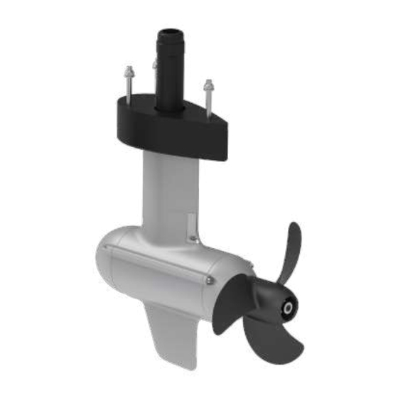
1.2 Parts and Diagrams Communication module Communication cable Power cable Main switch Product label Corrugated pipe M8 screw M8 washer M8 bolt Adjusting pad Supporting tube Motor Anode Propeller Skeg Figure 1-1 Pod Drive 1.0 Evo Power cable connector Dust cover Power cable Product label Heat sink... - Seite 11 Temperature line Corrugated pipe Phase line icon Three-phase line M8 locknut M8 bolt M8 washer Adjusting pad Supporting tube Propeller Motor Anode Skeg Figure 1-3 Pod Drive 3.0 Evo Temperature line Corrugated pipe Phase line icon Three-phase line Supporting tube M10 locknut M10 bolt M10 washer...
-
Seite 12: Technical Data
1.3 Technical Data Pod Drive 1.0 Evo Pod Drive 3.0 Evo Pod Drive 6.0 Evo Type Electric Pod Drive Motor Input Power 1 kW 3 kW 6 kW Rated Voltage Equivalent Power 3 hp 6 hp 9.9 hp Max Overall Efficiency Rated Rotation Speed 1200 rpm 2300 rpm... -
Seite 13: Declaration Of Conformity
Object of the Declaration: Product: Electric Outboard Motor Model: Pod Drive 1.0 Evo, Pod Drive 3.0 Evo, Pod Drive 6.0 Evo Company Name: Guangdong ePropulsion Technology Limited Address: Room 201, Bldg.17A, 4th XinZhu Road, SongShan Lake District, Dongguan City, Guangdong Province, China... -
Seite 14: Important Notes
2. Only adults who have fully read and understood this manual are allowed to operate this product. Read the full user manual carefully before operation, ePropulsion accepts no liability for any damage or malfunction caused by operations violating this manual. 3. Only boat owners who are familiar with their boats are allowed to use this pod system. -
Seite 15: Checking The Propeller
2 Checking the Propeller Before use, check the propeller and if necessary, eg. the original propeller is broken, change a new propeller. Follow instructions in Figure 2-1~2-3 to assemble a propeller properly. Assemble a propeller for Pod Drive1.0 Evo: Step1: Attach the washer. Step2: Fix the pin to the hole on motor shaft. - Seite 16 Assemble a propeller for Pod Drive3.0 Evo: Step1: Attach the Φ12 washer. Step2: Fix the pin to the hole of shaft. Step3: Attach the propeller. Step4: Attach the Φ12 washer. Step5: Tighten the nut with 19mm (3/4 inch) socket wrench. Step6: Attach the Anode.
-
Seite 17: Mounting The Motor
3 Mounting the Motor Step 1: Drill four holes in the proper position through the hull bottom. The suggested dimensions of the four holes are shown below (please refer to the fixing guide ) : Pod Drive1.0 Evo: 3xφ9mm φ37mm 52mm 85mm Figure 3-1... - Seite 18 Step 2: Hold the pod motor and insert its three bolts (Pod Drive 1.0 & 3.0 are M8, Pod Drive 6.0 Evo is M10) and supporting tube into the holes from below the hull bottom. Then lock the each bolt from inside the boat by a plain washer and a nut (Figure 3-4). Supporting Tube Locknuts Plain washers...
- Seite 19 Pod Drive 3.0 & 6.0 Evo: Step 3: Check the three phase lines U-U1, V-V1, W-W1, put the three phase lines into the phase line clamp; fix the terminal on the driver with the hexagon screw M10 and washer (tightening torque 8 -10Nm); finally insert the temperature line into the corre- sponding connector and tighten it.
- Seite 20 8.40mm 8.40mm 290mm Figure 3-8...
-
Seite 21: Connecting The Battery
Before connecting to a battery, make sure the main switch is off, and fix the battery and communication module/driver on the boat. 1. Connect the power cable of the pod drive to the battery. 2. If use ePropulsion batteries, please connect the battery and pod drive with a communication cable. Main... -
Seite 22: Connecting A Spirit Battery Plus (Only For Pod Drive 1.0 Evo)
4.2 Connecting a SPIRIT Battery Plus (Only for Pod Drive 1.0 Evo) If you use the Pod Drive 1.0 Evo and SPIRIT Battery Plus at the same time, please fol- low the steps below to connect SPIRIT Battery Plus and the communication module of Pod Drive 1.0 Evo: 1. Before connecting the battery and communication module, please fix the battery and communication module on the boat. -
Seite 23: Evo Remote Control
5 Evo Remote Control 5.1 Display Panel GPS Status Indicator Hydrogeneration Indicator Wireless Connecting Indicator Overheat Alert Kill Switch Status Indicator Safety Wristband Status Battery Level Indicator Indicator Number of Safety Wristband Battery Level / Voltage Fan Fault Current Speed Travelled Distance / Time or Remaining Distance / Time Distance / Time... - Seite 24 Buttons Functions 1. On any setting page, press " " button to view options for current setting. 2. In power-on state, when home page displays, press " " button and hold 10s to enter the throttle calibration page. 3. On home page, press " "...
- Seite 25 If users enter the page without setting any parameters, the current parameters displayed on the page will be saved as user parameters by default. Icons Functions Battery level Indicating approximate battery level. The solid blocks stand for remaining battery. indicator Indicating accurate current battery level percen- tage/battery voltage, is configurable in preferen- ce setting page.
- Seite 26 Icons Functions Blink:The motor fan has faults. Please con- Motor fan fault tact the dealer to check the fan wiring. Displaying real time travel distance/time. Set Distance/time units (MILE, KM (kilometer) and NM (nautical mile)) in preference setting page. display The time unit is HR (hour).
-
Seite 27: Charging
5.2 Charging The remote control has an in-built lithium battery for power supply. The battery will be charged automatically under normal use: get charged by solar power or wired con- nection. 5.2.1 Charging by Solar Power When the solar panel receives enough sunshine, it will generate electricity to charge the in-built lithium battery. - Seite 28 In this case, charging by wired connection is faster. Use a communication cable to connect the remote control and the communication module/driver. Then make sure the system battery is well connected to the pod drive and powered on. Battery Communication cable Figure 5-4 During long-term storage, ensure to charge the remote control every 6 months to avoid over-discharge.
-
Seite 29: Power Adjusting
5.3 Power Adjusting 5.3.1 Power Adjusting for Evo Remote Control Please place the kill switch on the Evo remote control before operation. The Evo Remote Control is mainly used to adjust the input power of the motor. When the battery is well connected and switched on, power on the Remote Control to start the pod drive, then slowly push the throttle forward position to increase the power. -
Seite 30: Recalibration
5.3.2 Recalibration If the error code displays as the figure 5-6, users should calibrate the throttle strictly as below steps. Figure 5-6 Recalibration process LCD Displaying Step1: Long press “ ” button for 10s until “CAL FO” displays. Step2: Push the throttle to the maximum forward power position, then press "... -
Seite 31: Use Of Kill Switch
Recalibration process LCD Displaying Step5: Push the throttle to zero position and press the “ ” button and return to the main page. 5.4 Use of Kill Switch • Attach the kill switch and tie its lanyard to your wrist or life jacket. • Stop the pod drive in emergency by detaching the kill switch. -
Seite 32: Use Of Safety Wristband
5.5 Use of Safety Wristband 5.5.1 Pairing Safety Wristband with Remote Control Press the " " and " " buttons and hold for a while to display the safety wristband icon and “SE”. At this time, approach the safety wristband that needs to be paired, turn on the safety wristband, and the remote control displays the “SUC”, indicating successfully pairing. -
Seite 33: Pairing Remote Control With The Pod Drive
When a wristband is disconnected or an emergency stop is performed, the stop command of other wristbands will not work until it returns to the normal state. 5.6 Pairing Remote Control with the Pod Drive Before use please pair remote control with the pod drive. There are two methods to pair the remote control. - Seite 34 Method 2. Pairing with Communication Cable Step1: Switch off system power and the remote control. Step2: Connect the remote control and the Communication module with a communi- cation cable. Step3: Switch on system power and the remote control. Wait for them to get paired in seconds.
-
Seite 35: Warning Messages
5.7 Warning Messages When the pod drive motor is running in abnormal conditions or out of order, a warning message with an error code will display on the LCD panel. Figure 5-12 is an example. Please find more error codes and corresponding solutions in the below table. Figure 5-12 Code Cause... - Seite 36 The motor has no power. All cha- then turn on the main switch. racters Pairing Remote Please refer to section 5.6 display Not paired Control with the Pod Drive. If the problem persists, please consult your ePropulsion authorized dealer for assistance.
-
Seite 37: Checklist Before Use
2. Remove the kill switch from the remote control. 3. Push the throttle to zero position. 4. Connect the battery with the pod drive. 5. If use ePropulsion battery, turn on the main switch. 6. Press “ ” button to turn on the remote control. -
Seite 38: Stopping The Pod Drive
8 Stopping the Pod Drive It’s recommended to stop the pod drive as the following procedures. 1. Return the throttle to zero position. 2. Wait until the motor stops, then detach the kill switch. 3. Press and hold the “ ” button until the remote control is switched off. 4. Turn off the main switch. -
Seite 39: Hydro Generation Function
3. The ship is not traveling or traveling too fast (Pod Drive 1.0 Evo is higher than 35km/h, Pod Drive 3.0/6.0 Evo is higher than 45km/h). 4. The battery level is higher than 90%. The hydro generation function can be used only when connecting ePropulsion batteries. Set up the hydro generation function When the Evo remote control and the machine are successfully connected, and the Evo remote control and the machine are both on. -
Seite 40: Maintenance
10 Maintenance 10.1 Propeller Maintenance Ensure the battery is disconnected before each check, as a rotating propeller is dangerous. Gloves are recommended to wear, in order to protect your hand from the sharp propeller edges. Check the propeller based on the following tips, then refer to the Chapter 2 Checking the Propeller to replace a new propeller if necessary. - Seite 41 Anode Figure 10-2 Replace Pod Drive6.0 Evo anode...
-
Seite 42: Transport And Storage
11 Transport and Storage Before long distance transport or long-term storage, please use ePropulsion original package to pack the pod drive. Figure 11-1 Make sure the pod drive gets adequate damping protection before transport and storage. Store the pod drive in a well-ventilated and dry area without direct sun exposure. -
Seite 43: Emergency Situations
12 Emergency Situations 12.1 Collision If the pod strikes some object beneath the water, please follow below procedures. 1. Stop the pod immediately and then turn off the main switch. 2. Check the mechanical structure to see if there are damages. 3. Return to the nearest harbor or pier in low power. 4. Call your dealer to check the pod. -
Seite 44: Warranty
13 Warranty The ePropulsion limited warranty is provided for the first end purchaser of an ePro- pulsion product. Consumers are entitled to a free repair or replacement of defective parts or parts which do not conform with the sales contract. This warranty operates in addition to your statutory rights under your local consumer law. -
Seite 45: Out Of Warranty
Free warranty is not transferable and will not be reissued. 13.2 Out of Warranty Make sure the product is properly packed during delivery, the original ePropulsion package is recommended. If the product get further damage due to improper packing during delivery, the furtherly damaged part will be deemed as out of warranty cover- age. - Seite 46 Note that the label should be kept intact. You can also deliver the product to your authorized ePropulsion dealer after getting confirmation. 3. The defective components or parts will be either repaired or replaced according to the diagnosis made by the ePropulsion authorized service partner.
- Seite 47 ACHTUNG! Die Montage des Motors darf nur von geschultem Fachpersonal durchgeführt werden! Vergewissern Sie sich, dass Ihr Rumpf von der Beschaffenheit und vom Zustand in der Lage ist, die Kräfte des Antriebs unter Volllast sowie bei schwerem Wetter mit starkem Wellengang, schadlos aufzunehmen! Ggf. muss der Rumpf entsprechend verstärkt werden, um die Kräfte sicher aufzunehmen und das Rumpfmaterial vor Er- müdung und so vor Schäden zu schützen.
-
Seite 48: Einführung
Einführung Vielen Dank, dass Sie sich für ein ePropulsion-Produkt entschieden haben. Wir be- danken uns für Ihr Vertrauen und freuen uns, dass Sie unser Unternehmen unter- stützen. Unser Angebot umfasst leistungsstarke elektrische Außenborder, elektrische Pod-Antriebe, Hilfs- bzw. Kajak-Motoren, zuverlässige Lithium-Batterien und Zubehör. -
Seite 49: Produktidentifikation
Produktidentifikation Die nachstehende Abbildung zeigt, wo sich die Seriennummern am Evo-Pod-Antrieb befindet. Bitte merken Sie sich, wo die Seriennummern zu finden sind und notieren Sie sie für die Inanspruchnahme von Garantie- und anderen Kundendienstleistungen. Abbildung 0-1 Electric Pod Drive Model: Pod Drive 3.0 Evo Rated Power: 3kW Rated Voltage: 48V S/N:... - Seite 50 Inhaltsverzeichnis Einführung ....................46 Verwendung dieses Handbuchs ...............46 Symbole.......................46 1 Produktübersicht ..................50 1.1 Lieferumfang ..................50 1.2 Teile und Zeichnungen ..............53 1.3 Technische Daten ................55 1.4 Konformitätserklärung ...............56 1.5 Wichtige Hinweise ................57 3 Den Motor montieren ................61 4 Anschließen der Batterie ................64 4.1 Anschließen einer 48-V-Batterie ............64 4.2 Anschließen einer SPIRIT-Batterie Plus (nur für den Pod Drive 1.0 Evo) ......................66...
- Seite 51 6 Checkliste vor der Verwendung .............83 7 Den Pod-Antrieb starten .................83 8 Den Pod-Antrieb ausschalten ..............84 9 Funktion Stromerzeugung mit Wasserkraft ..........85 10 Wartungsaufwand .................87 10.1 Propellerwartung ................87 10.2 Austausch der Anode ..............87 11 Transport und Aufbewahrung ..............89 12 Notsituationen ..................90 12.1 Kollision ...................90 12.2 Niedriger Batteriestand ..............90 13 Gewährleistung..................91...
-
Seite 52: Produktübersicht
1 Produktübersicht Die Evo-Pod-Antriebe 1.0/3.0/6.0 sind ein elektrische Pod-Antriebssysteme mit 1 kW/3kW/6kW Eingangsleistung. Sie werden entweder über die Evo-Fernsteuerung oder eine seitlich montierbare Steuerung betrieben. Pod-Antriebe sind bei Bootseig- nern in den letzten Jahrzehnten immer beliebter geworden. Allerdings sind nur we- nige hochwertige elektrische Pod-Systeme erhältlich. - Seite 53 Menge/Ein- Teil Abbildung heit Netzschalter 1 Satz Anschlusskabel für Evo-Pod 1.0 und Spirit-Batterie 1 Satz Plus (separat erhältlich) Pod Drive 3.0 Evo und Pod Drive 6.0 Evo Pod-Motor 1 Satz Kommunikations- 1 Satz modul Schraubenschlüs- 1 Satz selSatz Hauptschalterka- 1 Satz Auch vom Evo-Pod-Antrieb verwendet...
-
Seite 54: Fernsteuerung 1 Satz (Separat Erhältlich)
Weiteres Zubehör, wie Batterien, Ladegeräte usw., das in diesem Handbuch aufgeführt aber nicht in der vorliegenden Packliste enthalten ist, muss vom An- wender bei einem autorisierten ePropulsion-Händler erworben werden. Bewahren Sie die Originalverpackung von ePropulsion für Transport und La- gerung auf. -
Seite 55: Teile Und Zeichnungen
1.2 Teile und Zeichnungen Kommunikationsmodul Kommunikationskabel Netzkabel Hauptschalter Produktkennzeic Wellrohr M8-Schraube M8-Bolzen Unterlegscheibe Ausgleichsstück Wellrohr Motor Anode Propeller Skeg Abbildung 1-1 Pod Drive 1.0 Evo Netzkabelanschluss Schutzhaube Netzkabel Produktkenn- zeichnung Kühlkörper Lüfterkabel Befestigungssockel Ventil Kommunikationsanschluss für Batterie Kommunikationsanschluss für Geschwindigkeitsregler Abbildung 1-2 Treiber für Pod Drive 3.0 Evo &... - Seite 56 Temperatur-Anschlussleitung Wellrohr Phasen-Anschlussleitungssymbol Dreiphasige Anschlussleitung M8-Sicherungsmutter M8-Bolzen M8-Unterlegscheibe Ausgleichsstück Stützrohr Propeller Motor Anode Skeg Abbildung 1-3 Pod Drive 3.0 Evo Temperatur-Anschlussleitung Wellrohr Phasen-Anschlussleitungssymbol Dreiphasige Anschlussleitung Stützrohr M10-Sicherungsmutter M10-Bolzen M10-Unterlegscheibe Ausgleichsstück Anode Motor Propeller Skeg Abbildung 1-4 Pod Drive 6.0 Evo...
-
Seite 57: Technische Daten
1.3 Technische Daten Pod Drive 1.0 Evo Pod Drive 3.0 Evo Pod Drive 6.0 Evo Elektrischer Pod-Antriebe Leistungsaufnahme 1 kW 3 kW 6 kW Nennspannung Vergleichbare Benzin- 3 hp 6 hp 9.9 hp Außenborder Maximaler Gesamtwirkungsgrad Nenndrehzahl 1.200 U/min 2300 U/min 1500 U/min Evo Fernsteuerung / Evo seitliche Fernsteuerung / Evo Steuerungssystem... -
Seite 58: Konformitätserklärung
Gegenstand der Erklärung: Produkt: Elektrischer Außenbordmotor Modell: Pod Drive 1.0 Evo, Pod Drive 3.0 Evo, Pod Drive 6.0 Evo Name des Unternehmens: Guangdong ePropulsion Technology Limited Anschrift: Room 201, Bldg.17A, 4th XinZhu Road, SongShan Lake District, Dongguan City, Guangdong Province, China Der Gegenstand der Erklärung entspricht folgenden Richtlinien:... -
Seite 59: Wichtige Hinweise
2. Dieses Produk t dar f nur von Er wachsenen bedient werden, die dieses Handbuch vollständig gelesen und verstanden haben. Lesen Sie das gesamte Benutzerhandbuch vor der Inbetriebnahme sorgfältig durch. ePropulsion übernimmt keine Haftung für Schäden oder Fehlfunktionen, die durch die Nichteinhaltung der Anweisungen in diesem Handbuch entstanden sind. - Seite 60 11. Wenn ein Fehlercode angezeigt wird und der Pod-Antrieb nicht ordnungsgemäß funktionier t, bringen Sie den Geschwindigkeitsregler in die Nullstellung und unterbrechen die S tromversorgung. Sehen Sie dann im Abschnit t Warnmeldungen nach, um die Lösung zum Fehler zu ermitteln. 12. Stoppen Sie den Pod-Antrieb sofort, wenn jemand ins Wasser fällt. 13. Betreiben Sie den Pod-Antrieb nur, wenn sich der Propeller unter Wasser befindet.
-
Seite 61: Den Propeller Prüfen
2 Den Propeller prüfen Überprüfen Sie den Propeller vor der Inbetriebnahme und tauschen Sie ihn bei Bedarf aus, z. B. wenn der ursprüngliche Propeller defekt ist. Folgen Sie für die ordnungsgemäße Montage eines Propellers den Anweisungen in Abbildung 2-1~2-3. Zusammenbau eines Propellers für den Pod Drive 1.0 Evo: Schritt 1: Unterlegscheibe ansetzen. - Seite 62 Zusammenbau eines Propellers für den Pod Drive 3.0 Evo: Schritt 1: Befestigen Sie die Φ12er-Unter- legscheibe. Schritt 2: Fixieren Sie den Stift im Loch in der Welle. Schritt 3: Befestigen Sie den Propeller. Schritt 4: Befestigen Sie die Φ12er-Unter- legscheibe. Schritt 5: Ziehen Sie die Mutter mit einem 19-mm-(3/4 Zoll)-Steckschlüssel an.
-
Seite 63: Den Motor Montieren
3 Den Motor montieren Schritt 1: Bohren Sie vier Löcher an der richtigen Stelle in den Rumpfunterseite. Die empfohlenen Abmessungen der vier Bohrungen sind nachstehend dargestellt (siehe Montageschablone Pod Drive1.0 Evo: 3xφ9mm φ37mm 52mm 85mm Abbildung 3-1 Pod Drive 3.0 Evo: 3xφ9mm φ48mm 52mm... - Seite 64 Schritt 2: Halten Sie den Pod-Motor fest und setzen Sie die drei Bolzen (M8 für die Pod Drive 1.0 & 3.0, M10 für den Pod Drive 6.0) und das Stützrohr von der Unterseite des Rumpfes in die Löcher ein. Sichern Sie dann alle Bolzen vom Bootsinneren her mit jeweils einer Beilagscheibe und einer Mutter (Abbildung 3-4).
- Seite 65 Pod Drive 3.0 und 6.0 Evo: Schritt 3: Überprüfen Sie die drei Phasenleitungen U-U1, V-V1, W-W1, stecken Sie die drei Phasenleitungen in die Phasenleitungsklemme ein; befestigen Sie die Klemme mit der M10-Sechskantschraube und der Unterlegscheibe (Anzugsdrehmoment 8 -10 Nm) am Treiber; stecken Sie schließlich die Temperatur-Anschlussleitung in den ent- sprechenden Anschluss und ziehen Sie sie fest.
-
Seite 66: Anschließen Der Batterie
Sie die Batterie und das Kommunikationsmodul/den Kommunikationstreiber am Boot. 14. Schließen Sie das Netzkabel des Pod-Antriebs an die Batterie an. 15. Wenn Sie ePropulsion-Batterien verwenden, verbinden Sie bitte die Batterie und den Pod-Antrieb mit einem Verbindungskabel. - Seite 67 Haupt- schalter Haupt- schalter Verbindungskabel Verbindungskabel Abbildung 4-1 Abbildung 4-2 Kurzschluss der Batterie vermeiden. Unterbricht die Stromversorgung, wird der Außenborder gestoppt. Kurzschluss zwischen dem Hauptschalter und anderen Stromquellen vermei- den. Der Hauptschalter muss im Boot fest eingebaut werden. Die Rückwand des Hauptschalters darf niemals entfernt werden.
-
Seite 68: Anschließen Einer Spirit-Batterie Plus (Nur Für Den Pod Drive 1.0 Evo)
4.2 Anschließen einer SPIRIT-Batterie Plus (nur für den Pod Drive 1.0 Evo) Wenn Sie den Pod Drive 1.0 Evo zusammen mit der SPIRIT-Batterie Plus verwenden, befolgen Sie bitte die folgenden Schritte, um die SPIRIT-Batterie Plus und das Kom- munikationsmodul des Evo-Pod-Antriebs 1.0 anzuschließen: 1. -
Seite 69: Evo Fernsteuerung
5 Evo Fernsteuerung 5.1 LCD-Display GPS-Status Rekuperationsanzeige Anzeige kabellose Verbindung Warnung Übertemperatur Hinweis Reißleinenschalter Hinweis Sicherheitsarmband Anzeige Batteriestand Anzahl angemeldeter Sicherheitsarmbänder Batteriestand/Spannung Störung Ventilator Ist-Geschwindigkeit Anzeige zurückgelegter Strecke oder Zeit /verbleibender Strecke oder Zeit Strecke/Zeit Gashebel in die NULL-Posi- tion (RESET) Leistung Schwachstromanzeige der Fernbedienung... - Seite 70 Tasten Funktionen 1. Durch Drücken der „ “ Taste im Setup-Menü kann die aktuelle Einstellung gespeichert werden. Die nächste Option wird dann ange- wählt. 2. Durch langes Drücken der „ “ Taste im Setup-Menü wird die ak- tuelle Einstellung gespeichert und anschließend zum Hauptmenü ge- wechselt.
- Seite 71 Tasten Funktionen 1. Im eingeschalteten Zustand und beim Erscheinen des Hauptmenüs kann durch Drücken (kurz gedrückt halten) der „ “ Taste zum Menü der benutzerdefinierten Einstellungen gewechselt werden. Menü der benutzerdefinierten Einstellungen 2. Im Menü der benutzerdefinierten Einstellungen kann durch Drücken „Menü“...
- Seite 72 Beschreibung Funktionen Genaue Anzeige des aktuellen Batteriestands (%) / Batteriespannung. Konfigurationen können im Menü der benutzerdefi- Batte- nierten Einstellungen vorgenommen werden. 48.0V riestand / Beispiel: 100% Spannung : digitale Darstellung des aktuellen Batte- 100% riestands. : Anzeige der aktuellen Batteriespannung. 48.0V Leuchtet nicht: kein Empfang oder GPS funktio- GPS-Status...
- Seite 73 Beschreibung Funktionen Zurückge- : verbleibende Strecke oder Zeit. legte Stre- : zurückgelegte Strecke oder abgelaufene Zeit. cke / ver- Im Menü „Unit Setting“ kann die gewünschte Einheit, bleibende MILE, KM (Kilometer) oder NM (Seemeile), einge- Strecke stellt werden. Die Zeit wird in Stunden angezeigt. Zeigt die Echtzeit-Leistung des Geräts an.
-
Seite 74: Laden
5.2 Laden Die Evo Fernsteuerung besitzt eine integrierte Batterie als Stromversorgung. Beim normalen Betrieb wird die Batterie automatisch geladen, entweder über Solarenergie oder das Ladekabel. 5.2.1 Laden über Solarenergie (empfohlen) Beim Empfang ausreichender Sonnenstrahlung auf dem Solarpanel wird die integri- erte Lithium-Batterie automatisch geladen. - Seite 75 In diesem Fall kann das Laden durch ein Ladekabel beschleunigt werden. Die Evo Fernsteuerung mit einem Verbindungskabel an das Kommunikationsmodul / den Antrieb des Pod-Antriebs anschließen. Die Verbindung zwischen der Batterie und dem Pod-Antrieb aufrechterhalten und die Stromversorgung einschalten. Batterie Verbindungskabel Abb.
-
Seite 76: Leistungsanpassung
5.3 Leistungsanpassung 5.3.1 Motorleistung anpassen für Evo-Fernsteuerung Vor der Inbetriebnahme muss der Reißleinenschalter auf die Evo Fernsteuerung aufgelegt werden. Die Evo-Fernsteuerung wird hauptsächlich zum Anpassen der Motor-Eingangsleis- tung verwendet. Klemmen Sie die Batterie ordnungsgemäß an und schalten Sie sie ein. Schalten Sie anschließend die Fernsteuerung ein, um den Pod-Antrieb einzu- schalten und drücken Sie den Geschwindigkeitsregler langsam in die Vorwärts-Stel- lung, um die Drehzahl zu erhöhen. -
Seite 77: Kalibrieren
5.3.2 Kalibrieren Wenn der Fehlercode wie in der Abb. 5-6 auf dem Display erscheint, muss der Gashe- bel genau nach den unten beschriebenen Schritten kalibriert werden. Vor der Kalibrierung den zugehörigen Reißleinenschalter auf die vorgesehene Position legen. Andere magnetische Gegenstände dürfen nicht als Ersatz für den Reißleinenschalter verwendet werden. -
Seite 78: Reißleinenschalter Einsetzen
5.4 Reißleinenschalter einsetzen Die Reißleine um Ihr Handgelenk legen oder an Ihrer Schwimmweste befestigen. Im Notfall kann der Motor durch Entfernen des Reißleinenschalters gestoppt werden. Vor dem erneuten Start des Motors muss der Reißleinenschalter wieder auf die vorgesehene Position angebracht werden. Abb. -
Seite 79: Sicherheitsarmband Einsetzen
5.5 Sicherheitsarmband einsetzen 5.5.1 Registrierung des Sicherheitsarmbands mit der Evo Fernsteuerung (Kopplung) Die Taste „ “ und „ “ drücken und kurz gedrückt halten. Auf dem Display erschei- nen das Symbol für das Sicherheitsarmband und die Buchstaben SE. Das zu regis- trierende Sicherheitsarmband in die Nähe bringen und einschalten. -
Seite 80: Registrierung Der Evo Fernsteuerung Im Pod-Antrieb (Kopplung)
wird der Außenborder sofort gestoppt, wenn die Bedientaste des Sicherheitsarm- bands kurz betätigt wird. Dabei muss die Evo Fernsteuerung im Betrieb sein. Das Display der Evo Steuerung fängt an zu blinken und gibt einen warnenden Ton aus. Gleichzeitig blinkt das Symbol für das Armband und die darunter stehende Zahl (Anzahl der gemeldeten Armbänder) wird reduziert. - Seite 81 Schritt 5: Netzschalter einschalten und abwarten, bis die Kopplung des Pod-Antriebs mit der Evo Fernsteuerung automatisch abgeschlossen ist. Schritt 6: Nach dem Vorgang erscheint folgendes auf dem Display. (siehe Abbildung unten) Abb. 5-10 Falls die Kopplung nicht innerhalb von 60 Sekunden abgeschlossen wird, wieder- holen Sie die Schritte ab 3.
- Seite 82 Falls die Evo Fernsteuerung oder der Pod-Antrieb nicht ausgetauscht wurden und das Hauptmenü trotzdem wie oben dargestellt wird, dann überprüfen Sie: 1) ob die Evo Fernsteuerung nah genug am Pod-Antrieb ist. 2) ob alle Geräte richtig eingeschaltet sind. Falls das Display der Evo Fernsteuerung nach den Prüfungen das Hauptmenü immer noch wie oben (Abb.
-
Seite 83: Warnmeldungen
5.7 Warnmeldungen Bei fehlerhaftem Betrieb oder Störungen des Pod-Antriebs erscheinen Fehlercodes auf dem Display als Warnmeldungen. Gleichzeitig gibt die Evo Fernsteuerung einen anhaltenden Piepton aus. Die nachfolgende Tabelle hilft Ihnen, Maßnahmen für die Fehlerbehebung zu finden. Abbildung 5-12 dient nur als Beispiel. Weitere Fehlercodes und Maßnahmen zur Fehlerbehebung entnehmen Sie der nachfolgenden Tabelle. - Seite 84 Hebel muss neu kalibriert brieren“. werden Überprüfen, ob das Verbindungskabel Die Verbindung zwischen Mo- zwischen dem Motor und der ePropulsion tor und Batterie ist fehlerhaft Batterie richtig angeschlossen ist. Falls ja, Neustart durchführen. Mit einem Verbindungskabel die Evo Fern- Batteriestand der Evo Fern- steuerung mit dem Pod-Antrieb verbinden.
-
Seite 85: Checkliste Vor Der Verwendung
2. Ziehen Sie den Not-Aus-Schalter von der Fernsteuerung ab. 3. Bringen Sie den Geschwindigkeitsregler in die Leerlauf-Stellung. 4. Verbinden Sie die Batterie mit dem Pod-Antrieb. 5. Wenn Sie die ePropulsion-Batterie verwenden, schalten Sie den Hauptschalter ein. 6. Drücken Sie die „ “-Taste, um die Fernsteuerung einzuschalten. -
Seite 86: Den Pod-Antrieb Ausschalten
8 Den Pod-Antrieb ausschalten Es wird empfohlen, den Pod-Antrieb wie folgt anzuhalten. 1. Bringen Sie den Geschwindigkeitsregler wieder in die Leerlauf-Stellung. 2. Warten Sie, bis der Motor anhält, und ziehen Sie dann den Not-Aus-Schalter ab. 3. Halten Sie die „ “-Taste gedrückt, bis die Fernsteuerung ausgeschaltet ist. 4. Schalten Sie den Hauptschalter aus. -
Seite 87: Funktion Stromerzeugung Mit Wasserkraft
(standardmäßig aktiviert). 2. Die Evo Steuerung befindet sich in der NULL-Position. 3. Der Batteriestand (ePropulsion Batterie) liegt unter 90 %. 4. Wenn das Boot mit einer Fahrgeschwindigkeit von mehr als 6 km/h 4 Sekunden ge- fahren ist, startet die Rekuperation. - Seite 88 Abbildung 9-1...
-
Seite 89: Wartungsaufwand
10 Wartungsaufwand 10.1 Propellerwartung Stellen Sie sicher, dass die Batterie vor jeder Überprüfung abgeklemmt wird, da ein sich drehender Propeller gefährlich ist. Tragen Sie Handschuhe, um Ihre Hände vor den scharfen Propellerkanten zu schützen. Überprüfen Sie den Propeller anhand der folgenden Tipps und lesen Sie das Kapitel 2 Den Propeller prüfen, um den Propeller bei Bedarf durch einen neuen zu ersetzen. - Seite 90 Anode Abbildung 10-2 Anode des Pod Drive 6.0 Evo austauschen...
-
Seite 91: Transport Und Aufbewahrung
11 Transport und Aufbewahrung Vor einem Transport über eine größere Entfernung oder einer Langzeitlagerung soll- ten Sie den Pod-Antrieb in der Originalverpackung von ePropulsion verpacken. Abbildung 11-1 Vergewissern Sie sich vor Transport und Lagerung, dass der Pod-Antrieb ausre- ichend vor Feuchtigkeit geschützt ist. -
Seite 92: Notsituationen
12 Notsituationen 12.1 Kollision Berührt der Pod ein Objekt unter Wasser, gehen Sie bitte wie folgt vor: 1. Stoppen Sie den Motor sofort und schalten Sie dann den Hauptschalter aus. 2. Überprüfen Sie die mechanische Struktur, um festzustellen, ob Schäden vorlie- gen. -
Seite 93: Gewährleistung
Bauteilen. Die Festlegung der Garantiebedingungen dient zum Schutz der Verbraucherrechte. 13.1 Garantiebedingungen ePropulsion bietet für seine Produkte ab dem Kaufdatum für einen bestimmten Zeit- raum Garantieleistungen. Treten Qualitätsmängel innerhalb der Garantiefrist auf, kann der Benutzer seinen Garantieanspruch gegenüber der Fa. ePropulsion geltend ma- chen. -
Seite 94: Von Der Garantie Ausgenommen
13.2 Von der Garantie ausgenommen Das Produkt muss beim Einschicken zur Reparatur ausreichend verpackt sein. Es wird empfohlen, die Original-Verpackung von ePropulsion zu verwenden. Wenn Bauteile durch unzureichende Verpackung beim Einschicken beschädigt werden, unterliegen diese Bauteile nicht den vereinbarten Garantieleistungen. - Seite 95 Servicestelle ab. Achten Sie darauf, dass das Typenschild unbeschädigt ist. 3. Der Vertragshändler der Fa. ePropulsion kümmert sich um die Fehlerdiagnose und die Reparatur des defekten Bauteils oder veranlasst einen Umtausch. 4. Bei einem Garantiefall müssen Sie keine Kosten für die Reparatur oder den Um- tausch übernehmen.
- Seite 96 Wir freuen uns, Ihnen behilflich sein zu können. Thanks for reading this user manual. If you have any concerns or find any problems while reading, please don't hesitate to contact us. We are delighted to offer service for you. Guangdong ePropulsion Technology Limited Website: www.epropulsion.com Email: service@epropulsion.com...