Inhaltsverzeichnis
Werbung
Verfügbare Sprachen
Verfügbare Sprachen
Werbung
Inhaltsverzeichnis

Verwandte Anleitungen für Vaillant VRT-PZA 9148


Inhaltszusammenfassung für Vaillant VRT-PZA 9148
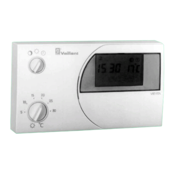
- Seite 1 VRT-PZA Art.-No. 9148 15...24 V-, 7 d- Raumtemperaturregler mit Wochen-Heizprogramm Roomthermostat with clock Thermostat d’ambiance à pro- grammation hebdomadaire Kamerthermostaat met schakelklok Termostato ambiente con temporizzatore settimanale Termostata ambiente con reloj...
- Seite 2 04 Raumtemperaturen einstellen Tagtemperatur und Nachttemperatur ansehen oder einstellen 05 Heizzeiten programmieren Grundprogramm, Heizzeiten anschauen und eingeben 06 Sonderfunktionen Party-Funktion, Frostschutz, Netzausfall 07 Vorlauftemperatur Einstellung am Vaillant Thermoblock Montageanleitung 08 Montage Einsatzbereich, Montagefolge 09 Elektro-Anschluß Anschluß am Thermoblock 10 Inbetriebnahme...
- Seite 3 Bedienung - Operating - Emploi - Bediening - Servizio - So - Hoja resúmen de instrucciones Fig. 1...
- Seite 4 A Bedienungsanleitung (Fig. 1, S. 3) 1 Betriebsartenschalter 7 Schaltpunkt-Taste zur Regelung auf zum Anschauen und Programmieren ständig Nachttemperatur der Heiz- und Absenkzeiten ständig Tagtemperatur eingegebenem Heizprogramm bei 8 Nachttemperatur-Taste zum Anschauen und Programmieren 2 Tagtemperaturwähler der Nachttemperatur zur Einstellung der zur Heizzeit gewünschten Raumtemperatur.
- Seite 5 Inhalt - contents - nomenclature - inhoud - contenuto A Bedienungsanleitung Seiten 4...15 B Montageanleitung Seiten 16...21 A Operating instructions page 22...33 B Installations instructions page 34...39 A Mode d’emploi page 40...51 B Instructions d’installation page 52...57 A Bedieningsvoorschrift blz. 58...69 B Montagevoorschrift blz.
-
Seite 6: Lüften Kurz Aber Kräftig
A Bedienungsanleitung – 1 Energiesparmöglichkeiten 1.1 Raumtemperatur begrenzen 1.4 Lüften kurz aber kräftig Begrenzen Sie die Raumtemperatur auf den Wert, der Öffnen Sie während der Heizperiode das Fenster nur für Ihr Behaglichkeitsempfinden gerade ausreicht. zum Lüften und nicht zur Temperaturregelung. Jedes Grad darüber hinaus bedeutet einen unnötigen Eine kurze Stoßlüftung ist wirkungsvoller und energie- Energieverbrauch von etwa 6%. -
Seite 7: A Bedienungsanleitung - 2 Betriebsart, Programmierung
A Bedienungsanleitung – 2 Betriebsart, Programmierung (Fig. 1, 2) 2.1 Betriebsart einstellen Von diesem Zustand aus können Sie die gewünschten Einstellfunktionen aufrufen, indem Sie die zugehörigen Mit dem Betriebsartenschalter (Fig. 2.1) können Sie die Funktionstasten (5...9) betätigen, z. B. Taste (6) für Betriebsweise Ihrer Heizungsanlage Ihren Bedürfnissen die Uhrzeiteinstellung. -
Seite 8: Uhrzeit Ablesen
A Bedienungsanleitung – 3 Uhreinstellung (Fig. 1, 3) 3.1 Uhrzeit ablesen Mit der Einstell-Taste – (11) stellen Sie die Uhr zurück. Im Display (3, Fig. 1) bedeuten: 1. Wochentag (Montag) Mit der Einstell-Taste + (12) stellen Sie die Uhr vor, in Fig. 3.4 auf 19 Uhr und 58 Minuten. 12:00 Aktuelle Uhrzeit: 12 Uhr und 0 Minuten Programmier-Taste Pro (10) drücken, damit... -
Seite 9: A Bedienungsanleitung - 4 Raumtemperaturen Einstellen
A Bedienungsanleitung – 4 Raumtemperaturen einstellen (Fig. 1, 4) 4.1 Tagtemperatur wählen Eine der Tasten (5), (6), (9), (11) oder (12) betätigen, im Display erscheint die Normalanzeige Am Tagtemperaturwähler (Fig. 4.1) stellen Sie die (Fig. 4.6) Raumtemperatur ein, die Ihnen während Ihres Aufent- halts im Wohnraum gerade ausreicht. -
Seite 10: Darstellung Der Heizzeiten
A Bedienungsanleitung – 5 Heizzeiten programmieren (Fig. 1, 5) 5.1 Darstellung der Heizzeiten 5.2 Heizzeiten anschauen Sie können für Ihren Raumtemperaturregler bis zu drei Schaltpunkt-Taste (7) drücken, im Display Heizzeiten pro Tag eingeben. Dabei müssen Sie erscheint das Tagesprofil des angezeigten Wochen- lediglich den Zeitpunkt für den Beginn und das Ende tages (Fig. -
Seite 11: A Bedienungsanleitung - 5 Heizzeiten Programmieren
A Bedienungsanleitung – 5 Heizzeiten programmieren (Fig. 1, 5) 5.3 Grundprogramm 5.4 Heizzeiten eingeben Falls Sie keine Änderung der Schaltzeiten vornehmen, Sie können anstelle des Grundprogrammes individuelle arbeitet der Raumtemperaturregler nach dem werk- Heizzeiten eingeben: seitigen Grundprogramm: Programmier-Taste Pro (10) drücken der Heizzeit mit Tagtemperatur: 06:00 bis 22:00 Raumtemperaturregler schaltet in den Programmier-... -
Seite 12: Beispiel Für Die Heizzeiteingabe
A Bedienungsanleitung – 5 Heizzeiten programmieren (Fig. 1, 5) Durch längere Betätigung einer der Einstelltasten erfolgt Schaltpunkt-Taste betätigen (Fig. 5.16) eine schnellere Zeitverstellung, zunächst in 10-Minuten- Schritten, bei längerer Betätigung in 1-Stunden- Einstell-Taste – betätigen bis 9:00 (Fig. 5.17) Schritten. Programmier-Taste Pro drücken, der Raum- Schaltpunkt-Taste (7) betätigen, bis der zu... - Seite 13 A Bedienungsanleitung – 5 Heizzeiten programmieren (Fig. 1, 5) 5.7 Heizzeiten für mehrere Wochentage Wochentag-Taste 1..7 (5) drücken, damit können Sie weitere Wochentage auswählen für die Sie programmieren bzw. kopieren durch Betätigen der Block Taste b (9) gemeinsame Sie können für mehrere Wochentage gleichzeitig Heiz- Heizzeiten übernehmen.
-
Seite 14: A Bedienungsanleitung - 6 Sonderfunktionen
A Bedienungsanleitung – 6 Sonderfunktionen (Fig. 1, 6) 6.1 Party-Funktion 6.3 Betrieb bei Netzausfall Diese Funktion läßt sich nur bei Regelung nach Heiz- Bei Stromausfall läuft die Schaltuhr Ihres Raum- programm aktivieren. temperaturreglers über einen Kondensator einige Zeit weiter (Gangreserve), das Wochenheizprogramm Party-Taste , (4) drücken, im Display erscheint das bleibt erhalten. -
Seite 15: A Bedienungsanleitung - 7 Vorlauftemperatur
A Bedienungsanleitung – 7 Vorlauftemperatur Einstellung am Vaillant Thermoblock Stellen Sie den Vorlauftemperaturregler an Ihrem Vaillant Thermoblock entsprechend nachstehender Empfehlung ein: Bei Heizungsanlagen im Niedertemperaturbereich mit Vorlauftemperaturen bis max. 75 °C: Stellung 7. Bei Heizungsanlagen mit Vorlauftemperaturen bis max. 90 °C:... -
Seite 16: Pumpenschaltung
„durchlaufende Pumpe”. Stellen Sie den Pumpen- Der Raumtemperaturregler VRT-PZA läßt sich problem- Betriebsartenschalter auf „s” oder „II” . los an alle Vaillant Thermoblocks VC...bzw. VCW... 8.4 Funk-Entstörung mit 15...24 V-Reglereingang (Klemmen 7 , 8, 9) anschließen. Ausführliche Informationen enthalten die Der Raumtemperaturregler ist gemäß... -
Seite 17: B Montageanleitung - 8 Montage
B Montageanleitung – 8 Montage (Fig. 7) 8.5 Montageort 8.6 Montagefolge Der Raumtemperaturregler ist an einem für seine Die elektrischen Leitungen zum Thermoblock werden Funktion geeigneten Ort anzubringen. Der günstigste zweckmäßigerweise schon vor Anbringen des Montageort ist meistens im Hauptwohnraum an einer Raumtemperaturregler-Oberteils (7) verlegt. - Seite 18 Vaillant Thermoblocks angeschlossen werden. Der elektrische Anschluß soll von einem anerkannten Fachhandwerksbetrieb vorgenommen werden. Die Anschlußverdrahtung an die Klemmen 7 , 8, 9 eines Vaillant Thermoblocks VC... bzw. VCW... ist ent- sprechend Fig. 9 vorzunehmen. Das Anschlußkabel durch die Kabeldurchführung (11), legen.
-
Seite 19: Zweipunkt-/Analog (Stetig)-Regelung
B Montageanleitung – 10 Inbetriebnahme (Fig. 10) 10.2 Zweipunkt-/Analog 10.1 Erstinbetriebnahme (Stetig)-Regelung Die erste Inbetriebnahme des Raumtemperaturreglers Werkseitig regelt der VRT-PZA im Zweipunktbetrieb. gemeinsam mit der Heizungsanlage sowie die erste Eingabe entsprechend den Wünschen des Benutzers soll von einem anerkannten Fachhandwerksbetrieb Die Umstellung ist durch den Fachhandwerksbetrieb möglich: vorgenommen werden, der die Verantwortung für die... -
Seite 20: Betriebsbereitstellung
B Montageanleitung – 10 Inbetriebnahme (Fig. 10) 10.3 12-/24-Stunden-Anzeige 10.4 Betriebsbereitstellung Die Umstellung ist durch den Fachhandwerksbetrieb Nach jeder dieser Einstellungen den Raumtemperatur- möglich: regler auf die Montageplatte aufsetzen und den Hauptschalter des Thermoblocks auf „I” stellen. Hauptschalter des Thermoblocks auf „0” stellen, Raumtemperaturregler-Oberteil von der Montageplatte entspr. -
Seite 21: Technische Daten
1 1 Technische Daten Gerätetyp VRT-PZA Art.-Nr. 9148 Betriebsspannung vom VC bzw. VCW 15...24 V- Stromaufnahme 30 mA Temperatur-Einstellbereich Tagtemperatur 5...30 °C Nachttemperatur 5...20 °C Mögliche Heizzeiten 3 pro Tag Proportionalbereich Schaltdifferenz Erfassung der Ist-/Solltemperatur alle 30 s Gangreserve 10 min Abmessungen Breite 148 mm Höhe... - Seite 22 A Operating instructions (Fig. 1, p. 3) 1 Operating mode switch 7 Change-over key For control at For indicatlng and programming the heating periods constantly night-time in position and the drop periods constantly daytime temperature in position 8 Night-time temperature key entered heating programme in position For indicating and programming the night-time...
-
Seite 23: Operating Conditions
A Operating instructions – 1 Application (Fig. 1, p. 3) 1.1 Operating conditions Heating periods can be programmed individually for every day and together for several days. In addition, With the room thermostat VRT-PZA, the temperature for the factory-set basic programme can be readjusted at the heating periods „day”... - Seite 24 A Operating instructions – 1 Application (Fig. 1, p. 3) 1.2 Possibilities for energy saving Ventilate briefly but thoroughly During the heating period, open windows only for Limiting the room temperature airing and not for regulating the room temperature. Limit the room temperature to the minimum value at A brief but vigorous airing is more effective and more which you still feel comfortable.
-
Seite 25: Setting The Operating Mode
A Operating instructions – 2 Operating mode - notes on programming (Fig. 1, 2) 2.1 Setting the operating mode for setting the time. The letter p next to the setting indicates that these values can be altered, see fig. 2.3. With the operating mode switch (2, fig. - Seite 26 A Operating instructions – 3 Setting the timer (Fig. 1, 3) 3.1 Reading the time With the setting key – (11), the timer is set back. Description of display (3, fig. 1): With the setting key + (12), the timer is put forward, in fig.
- Seite 27 A Operating instructions – 4 Setting the room temperatures (Fig. 1, 4) 4.1 Selecting the daytime temperature 4.3 Altering the night-time temperature With the temperature selector (fig. 4.1), set the room Set the room temperature for the drop periods with temperature at which you still feel comfortable in your „night-time temperature“...
- Seite 28 A Operating instructions – 5 Programming heating periods (Fig. 1, p. 3, 5) 5.1 Indicating the heating programme 5.2 Indicate the heating programme Up to three heating periods per day can be entered in Press change-over key (7), the display shows your room thermostat.
- Seite 29 A Operating instructions – 5 Programming heating periods (Fig. 1, 5) 5.3 Basic programme 5.4 Entering heating periods If the change-over times are not altered, the room It is possible to enter different heating periods Iinstead thermostat operates according to the factory-set basic of the basic programme: programme: Press Pro programming key (10), the room...
- Seite 30 A Operating instructions – 5 Programming heating periods (Fig. 1, 5) By pressing the + or – key without interruption, Press setting key – until 5:00 (fig. 5.15) appears. the time is altered rapidly, first in 10-min. steps. then in 1-hour steps.
- Seite 31 A Operating instructions – 5 Programming heating periods (Fig. 1, 5) 5.7 Simultaneously programming Press day key 1..7 (5) to select further days for which hoint heating periods are copied b pressing the or copying resp. heating periods block key b (9). The display shows fixed numbers for for several days the days of the block with joint flashes (fig 5.21).
-
Seite 32: Operation In The Case Of A Power
B Installations instructions – 6 Special operating conditions (Fig. 1, 6) 6.1 Party operation 6.3 Operation in the case of a power This operating condition can only be activated if the failure temperatures are controlled according to a heating In the case of a power failure, the timer of your room programme. - Seite 33 B Installations instructions – 7 Setting the flow temperature Set the flow thermostat at your Vaillant THERMOcompact/COMBlcompact according to the below-mentioned recommendation: In the case of heating installations at low temperatures with flow temperatures up to max 75°C: position 7.
- Seite 34 The mounting plate may be connected to the already installation, this suppression factor „N“ will be gener- existing connections of a former type of Vaillant room ally met provided that all other devices are factor „N“ thermostats or even replace a room thermostat built interference-suppressed.
-
Seite 35: Installation Sequence
B Installations instructions – 8 Istallation (Fig. 7) 8.6 Installation sequence 8.5 Positioning The room thermostat must be installed in a position We recommend to install the connecting cable to the THERMOcompact/COMBlcompact before mounting which ensures a correct functioning. Generally, the the front casing of the room thermostat. - Seite 36 THERMOcompact/COMBlcompact Please note: The room thermostat VRT-PZA must only be connected to the low-voltage terminals 7, 8, 9 of a Vaillant THERMOcompact/COMBlcompact. The electrical connection must be carried out by an authorized installer. The connection to the terminals 7, 8, 9 of a Vaillant THERMOcompact/COMBlcompact VC...
- Seite 37 B Installations instructions – 10 Initial taking into operation (Fig. 10) 10.1 Check operation 10.2 On/off analog (continuous) The initial taking into operation of the room thermostat control together with the heating installation as well as the first The VRT-PZA is factory-set to on/off control. setting of the heating programme according to the The authorized installer can change the setting Set the wishes of the user shall be carried out by the authorized...
- Seite 38 B Installations instructions – 10 Initial taking into operation (Fig. 1 0) 10.3 12 h/24 h reading 10.4 Make the room thermostat The change can be carried out by the authorized ready for operation installer: After this setting, place the room thermostat on the mounting plate.
- Seite 39 B Installations Instructions – 1 1 Technical data Appliance type VRT-PZA Article no. 9148 Operating voltage for VC or VCW 24V- Current input < 30 mA Temperature setting range daytime temperature 5...30 °C night-time temperature 5...20 °C Possible heating periods 3 per hour Proportional range Switching difference...
- Seite 40 A Mode d’emploi (Fig. 1, p. 3) 1 Commutateur du mode de 6 Touche „heure“ pour introduire l’heure exacte et les temps de fonctionnement commutation pour régler a la température „nuit“ 7 Touche „point de commutation“ en permanence en position pour indiquer et programmer les périodes de chauffe à...
- Seite 41 A Mode d’emploi – 1 Applications (Fig. 1, p. 3) 1.1 Fonctions Avec la touche „party“ (4) il est également possible Votre thermostat d’ambiance VRT-PZA vous permet de de continuer le service du chauffage également régler les températures pour les périodes de chauffe pendant la période d’abaissement suivante.
- Seite 42 A Mode d’emploi – 1 Application (Fig. 1, p. 3) 1.2 Possibilités d’économie d’énergie Aérer brièvement, mais énergiquement Une ventilation brève et complète est plus efficace et Limiter la température ambiante coûte moins d’énergie que des fenêtres qui restent Limiter la température ambiante à une valeur suffisante entre-ouvertes pendant une période prolongée.
- Seite 43 A Mode d’emploi – 2 Mode de fonctionnement – informations sur la programmation (Fig. 1, 2) 2.1 Régler le mode de fonctionnemet L’affichage indique Pro (2.2). Maintenant, il est possible de faire indiquer les réglages désirés à l’aide Le commutateur de régime de fonctionnement de touches respectives (5-9), p.
-
Seite 44: Lecture De L'heure
A Mode d’emploi – 3 Réglage de l’heure (Fig. 3) 3.1 Lecture de l’heure Pour retarder l’horloge, appuyer sur la touche de réglage – (11). Les affichages signifient (3, fig. 1): Pour avancer l’horloge, appuyer sur la touche de 1er jour de la semaine (lundi) réglage + (12), dans fig. - Seite 45 A Mode d’emploi – 4 Réglages des températures ambiantes (Fig. 1, 4) 4. 1 Réglages des températures 4.3 Modifier la température „nuit“ La température ambiante pour les périodes ambiantes d'abaissement avec „température nuit“ est ajustée Régler au sélecteur de température (4.1) la température comme suit: ambiante qui convient à...
- Seite 46 A Mode d’emploi – 5 Programmation des périodes de chauffe (Fig. 1, 5) 5.1 Indication des périodes de chauffe 5.2 Indiquer le programme de chauffe Votre thermostat d’ambiance vous permet de pro- Appuyer sur la touche point de commutation grammer trois périodes de chauffe par jour. Pour cela (7), I’affichage montre le programme journalier du il suffit de régler le temps pour le début et la fin de jour indiqué...
- Seite 47 A Mode d’emploi – 5 Programmation des périodes de chauffe (Fig. 1, 5) 5.3 Programme de base 5.4 Introduire des périodes de chauffe Si les temps de commutation ne doivent pas ˆ e tre Il est possible d’introduire des périodes individuelles modifiés, le thermostat d’ambiance fonctionne selon le de chauffe au lieu du programme de base: programme de base réglé...
- Seite 48 A Mode d’emploi – 5 Programmation des périodes de chauffe (Fig. 1, 5) En appuyant plus longtemps sur la touche + ou –, vous Appuyer sur la touche de réglage - jusqu’à obtiendrez une plus grande vitesse de changement de 5:00 (fig.
- Seite 49 A Mode d’emploi – 5 Programmation des périodes de chauffe (Fig. 1, 5) 5.7 Programmer ou copier à la fois des Appuyer sur la touche bloc b (9) pour fixer ce jour comme jour de source. L’affichage montre CP périodes de chauffe pour plusieurs (fig.
- Seite 50 A Mode d’emploi – 6 Fonctions spéciales (Fig. 1, 6) 6.1 Régime „party“ 6.3 Fonctionnement en cas de panne Ce régime peut seulement être activé en cas de de courant (max. 1 heure) réglage selon le programme de chauffe. En cas de panne de courant, l’horloge de votre thermo- stat d’ambiance peut gontinuer à...
- Seite 51 A Mode d’emploi – 7 Régler la température de départ Réglage de la chaudière Thermotop/Thermocompact Régler l’aquastat sur votre Thermocompact/Thermotop comme suit: pour des systèmes de chauffage à basse température avec des températures de départ jusqu’à 75 °C max: position 7. pour des systèmes de chauffage avec des températures de départ jusqu’à...
- Seite 52 8.4 Antiparasitage ˆ e tre raccordé aux raccordements existants d’un thermo- Le thermostat d’ambiance est déparasité selon la stat d’ambiance Vaillant précédent mais aussi rempla- norme VDE 0875 avec le facteur d’antiparasitage „N“. cer un thermostat d’ambiance d’un autre fabricant En cas d’utilisation avec d’autres appareils dans un...
-
Seite 53: Emplacement
B Instructions d’Installation – 8 Installation (Fig. 7) 8.5 Emplacement 8.6 Suite des opérations d’installation Le thermostat d’ambiance doit être placé à un endroit Nous recommandons de poser les câblages approprié pour son fonctionnement. L’endroit le plus électriques avant d’installer le thermostat d’ambiance. favorable est en général une paroi intérieure de la Pour la fixation, procéder comme suit: salle de séjour, à... - Seite 54 B Instructions d’installation – 9 Raccordement électrique (Fig. 8, 9) Raccordement à la chaudière Thermotop/Thermocompact A noter: le thermostat d’ambiance VRT-QZA est seulement raccordé aux bornes basse tension 7, 8, 9 de la Thermotop/Thermocompact. Le raccordement électri- que doit être effectué par un professionnel qualifié. Le raccordement aux bornes 7, 8, 9 d’une Thermotop/ Thermocompact VC ou VCW est à...
-
Seite 55: Vérification Du Fonctionnement
B Instructions d’installation – 10 Première muse en service (Fig. 10) 10. 1 Vérification du fonctionnement 10.2 Régulation à action constante/ La première mise en service du thermostat d’ambiance „tout ou rien“ selon les désirs du client, conjointement avec le système Le thermostat d’ambiance est préréglé... -
Seite 56: Préparation À La Mise En Service
B Instructions d’installation – 10 Première muse en service (Fig. 10) 10.3 Affichage12 h/24 h 10.4 Préparation à la mise en service l’installateur qualifié peut procéder au changement: Remettre le thermostat d’ambiance sur la socle de fixation après ce réglage. Enlever les fusibles devant l’appareil de chauffage. - Seite 57 B Instructions d’installation – 11 Caractéristiques techniques Type d’appareil VRT-PZA Référence 9148 Tension de service 24 V- du VC ou VCW Consommation < 30 mA Plage de réglage de la température température„jour“ 5...30 °C température„nuit“ 5...20 °C Mesure de la température actuelle de consigne toutes les 30 sec.
- Seite 58 A Bedieningsvoorschrift (Fig. 1, blz. 3) 1 Voorkeuzeschakelaar 7 Schakelpunt-toets Voor het regelen van: Voor het instellen en controleren van de verwarmings- nachttemperatuur en nachtverlagingsperioden. dagtemperatuur 8 Nachttemperatuur-toets het ingestelde verwarmingsprogramma bij Voor het instellen en controleren van de 2 Temperatuurinstelknop nachttemperatuur.
- Seite 59 A Bedieningsvoorschrift – 1 Toepassing (Fig. 1, blz. 3) 1.1 Functies Bovendien kunt u te allen tijde het basisprogramma weer instellen. De kamerthermostaat VRT-PZA maakt het u mogelijk de dag- en nachttemperaturen (nachtverlaging), onafhanke- De Party-knop (4) maakt het mogelijk om, na beëin- lijk van elkaar, te regelen.
- Seite 60 A Bedieningsvoorschrift – 1 Toepassing (Fig. 1, blz. 3) 1.2 Mogelijkheden tot Kort, maar krachtig ventileren Een volledige ventilatie gedurende een korte tijd energiebesparing bespaart meer energie dan lang openstaande Het begrenzen van de kamertemperatuur klapramen. Gedurende het ventileren de temperatuur U kunt de kamertemperatuur begrenzen op de waarde ca.
- Seite 61 A Bedieningsvoorschrift – 2 Instelmogelijkheden – Programmeertips (Fig. 1, 2) 2.1 Instelmogelijkheden toetsen. Bijv. toets (6) voor de tijdinstelling. De hoofdletter P naast deze instelling, geeft aan dat Met de voorkeuzeschakelaar (afb. 1.1) kunt u uw CV- u deze kunt wijzigen (zie afb. 2.3). De programma- installatie naar uw persoonlijke wensen laten functio- functie kunt u uitschakelen door de toets Pro nog- neren.
-
Seite 62: Dag- En Tijdinstellen
A Bedieningsvoorschrift – 3 Klokinstelling (Fig. 3, blz. 95) 3.1 Het aflezen van de tijd Met de instelknop – (11) zet u de tijd terug. In display (3, afb. 1) betekent: Met de instelknop + (12) zet u de tijd vooruit. In afb. - Seite 63 A Bedieningsvoorschrift – 4 Kamertemperatuur instellen (Fig. 4, blz. 96) 4.1 Dagtemperatuur instellen 4.3 Nachttemperatuur wijzigen Met de temperatuurinstelknop (afb. 4.1) kunt u de De kamertemperatuur voor de nachtverlaging stelt u kamertemperatuur instellen, die u tijdens uw verblijf in als volgt in: de woonkamer net voldoende vindt.
- Seite 64 A Bedieningsvoorschrift – 5 Programmeren van verwarmingsperioden (Fig. 5, blz. 97) 5.1 Aanduiding van verwarmings- 5.2 Verwarmingsprogramma aflezen Als u de schakelpunt-toets (7) indrukt zullen in programma’s de display de schakeltijden van de aangegeven dag U kunt met deze thermostaat drie verwarmingsperioden (afb.
-
Seite 65: Verwarmingsprogramma Instellen
A Bedieningsvoorschrift – 5 Programmeren van verwarmingsperioden (Fig. 5, blz. 97) 5.3 Basisprogramma 5.4 Verwarmingsprogramma instellen Indien u geen wijzigingen aanbrengt in het pro- U kunt, i.p.v. het basisprogramma, ook uw eigen gramma, zal de kamerthermostaat iedere dag volgens programmering instellen. het basisprogramma werken: Programma-toets Pro (10) indrukken (afb. - Seite 66 A Bedieningsvoorschrift – 5 Programmeren van verwarmingsperioden (Fig. 5, blz. 97, 99, 100) Door de toetsen + of – langere tijd ingedrukt te houden Instel-toets – indrukken tot 05.00 (afb. 5.15) zal de tijdverstelling versnellen. Eerst in stappen van 10 minuten, later in stappen van 1 uur. Schakelpunt-toets indrukken (afb.
- Seite 67 A Bedieningsvoorschrift – 5 Programmeren van verwarmingsperioden (Fig. 5, blz. 97, 99, 100) Dag-toets 1..7 (5) indrukken, zodat u verde 5.7 Verwarmingsperioden dagen kunt selecteren en - door het indrukker van toets voor meerdere dagen tegelijk b (9) - kopiëren. programmeren/kopiëren U kunt voor meerdere dagen tegelijk een In de display worden de bij het blok behorende dagen...
-
Seite 68: Vorstbeveiliging
A Bedieningsvoorschrift – 6 Speciale functies (Fig. 6, blz. 101) 6.1 Party-knop 6.3 Functioneren bij wegvallen Deze functie is alleen te activeren bij gebruik van het netspanning verwarmingsprogramma Bij het wegvallen van de netspanning zal de schakel- klok van de kamerthermostaat door middel van een Indien u de Party-knop (4) indrukt zal in de display condensator enige tijd doorlopen (gangreserve). - Seite 69 A Bedieningsvoorschrift – 7 Aanvoertemperatuur instellen Instelling aan het toestel Stel de ketelwaterthermostaat van uw Vaillant verwarmingstoestel als volgt in: Installaties geschikt voor een temperatuur tot 75 °C; stand 7 Installaties geschikt voor een temperatuur tot 90 °C; stand 9...
- Seite 70 De montageplaat past op de boor- „N“ ontstoord. In combinatie met andere toestellen zal gaten van oudere typen Vaillant thermostaten. De VRT- de thermostaat deze norm behouden, mits de andere PZA kan ook gemonteerd worden op de plaats van toestellen ook minimaal aan deze norm voldoen.
- Seite 71 B Montagevoorschrift – 8 Montage (Fig. 7) 8.5 Montageplaats 8.6 Montage volgorde Om op een juiste wijze te kunnen functioneren dient De elektrische bedrading naar het verwarmingstoestel de thermostaat op een hiervoor geschikte plaats dient aangebracht te zijn, voordat de montageplaat gemonteerd te worden.
- Seite 72 B Montagevoorschrift – 9 Elektrische aansluiting (Fig. 8, 9) De VRT-PZA mag uitsluitend op de laagspannings- klemmen 7 , 8 en 9 van een Vaillant Thermocompact VC/VCW aangesloten worden. Dit dient door een erkend installateur gedaan te worden. Alvorens met de aansluiting van de elektrische bedrading te beginnen, dient de hoofdschakelaar van de CV-ketel op „0“...
- Seite 73 B Montagevoorschrift – 10 Inbedrijfstelling (Fig. 10) 10.1 Functietest 10.2 Omschakeling van Aan/ De inbedrijfstelling van de thermostaat (en installatie) Uit naar Proportionele regeling evenals de eerste programmering volgens de wensen Af fabriek functioneert de VRT-PZA als aan/uit rege- van de gebruiker, dienen door een erkend installateur laar.
-
Seite 74: Inbedrijfname
Deze instelling is door uw installateur te wijzigen. Eerst dient de hoofdschakelaar van de Thermocompact Hiertoe dient eerst de hoofdschakelaar van de Vaillant op „0“ gezet te worden. Thermocompact op „0“ gezet te worden. De afdek-... - Seite 75 B Montagevoorschrift – 1 1 Technische gegevens Toesteltype VRT-PZA Art. nummer 9148 Bedrijfsspanning 20 V= van VC/VCW Stroomafname < 30 mA Temperatuurinstelbereik: Dagtemperatuur 5...30 °C Nachttemperatuur 5...20 °C Kortste schakelbereik verwarmingsperioden 10 min. Proportioneel bereik Schakelverschil Gangreserve 0,5 h Afmetingen: Breedte 148 mm Hoogte 85 mm...
- Seite 76 A Istruzioni d’uso (Fig. 1, pag. 3) 1 Selettore modi operativi 7 Tasto punti di commutazione per registrare a scelta i modi operativi per verificare e programmare le fasi di riscaldamento temperatura notturna continua e d’abbassamento temperatura diurna continua 8 Tasto temperatura notturna programma di riscaldamento impostato con per verificare e programmare la temperatura notturna 2 Selettore della temperatura diurna...
- Seite 77 A Istruzioni d’uso – 1 Applicazione (Fig. 1, pag. 3) 1.1 Funzioni Inoltre potrete regolare in qualsiasi momento il programma di base preregolato in fabbrica. Il termostato ambiente VRT-PZA serve alla regolazione separata delle temperature nelle fasi di riscaldamento Grazie al tasto Party (4) è...
- Seite 78 A Istruzioni d’uso – 1 Applicazione (Fig. 1, pag. 3) 1.2 Possibilità per il risparmio Ventilare in modo breve ma intenso Durante il periodo di riscaldamento aprite la finestra energetico solo per arieggiare e non per regolare la temperatura. Limitare la temperatura ambiente Una breve ed intensa ventilazione è...
- Seite 79 A Istruzioni d’uso – 2 Modooperativo – Indicazioni di programmazione (Fig. 1, 2) 2.1 Selezionare il modo operativo 2.2 Indicazioni di programmazione Mediante il selettore modi operativi (fig. 2.1) è possi- generali bile adattare il modo operativo del Vostro impianto di Tramite il tasto Pro (10) viene attivato il modo riscaldamento alle Vostre esigenze.
- Seite 80 A Istruzioni d’uso – 3 Regolazione del temporizzatore (Fig. 1, 3) 3.1 Lettura dell’ora Per mezzo del tasto di regolazione – (11) potete spostare l’ora indietro. Le indicazioni nel display (3, fig. 1) significano: Per mezzo del tasto di regolazione + (12) potete 1°...
- Seite 81 A Istruzioni d’uso – 4 Regolazione delle temperature ambiente (Fig. 1, 4) 4.1 Selezionare la temperatura diurna 4.3 Modificare la temperatura notturna Impostare il selettore della temperatura diurna (4.1) Per regolare la temperatura ambiente per le fasi alla temperatura ambiente, sufficiente per il Vostro d’abbassamento mediante „temperatura notturna“...
- Seite 82 A Istruzioni d’uso – 5 Programmare le fasi di riscaldamento (Fig. 1, 5) 5.1 Rappresentazione dei programmi 5.2 Indicazione del programma di di riscaldamento riscaldamento Con il vostro termostato ambiente è possibile program- Premere il tasto punto di commutazione (7), mare fino a 3 periodi di riscaldamento per ogni nel display compare il profilo giornaliero del giorno giorno.
- Seite 83 A Istruzioni d’uso – 5 Programmare le fasi di riscaldamento (Fig. 1, 5) 5.4 Registrare le fasi di riscaldamento 5.3 Programma di base Se non modificate i momenti d’intervento, il termostato Invece di riscaldare in funzione del programma di base si possono registrare periodi di riscaldamento ambiente funziona in base al programma di base individuali: regolato in fabbrica:...
- Seite 84 A Istruzioni d’uso – 5 Programmare le fasi di riscaldamento (Fig. 1, 5) Premendo a lungo il tasto + o –, potete spostare premere il tasto d’impostazione – fino a 5:00 l’ora in modo più rapido, prima a passi di 10 min. e (fig.
- Seite 85 A Istruzioni d’uso – 5 Programmare le fasi di riscaldamento (Fig. 1, 5) 5.7 Programmare o copiare allo stesso Premere il tasto giornaliero 1..7 (5) per scegliere ulteriori giorni, se premete il tasto blocchi b (9) sarà tempo le fasi di riscaldamento per possibile trasmettere le fasi di riscaldamento comuni.
-
Seite 86: Funzione Party
A Istruzioni d’uso – 6 Funzioni speciali (Fig. 1, 6) 6.1 Funzione Party 6.3 Funzionamento in caso di Questa funzione può essere attivata soltanto se il mancanza di corrente termostato è regolato in base al programma di In caso di mancanza di corrente l’orologio del Vostro riscaldamento. - Seite 87 A Istruzioni d’uso – 7 Regolare la temperatura in andata Regolazione sulla Vaillant Tecnoblock Procedete alla regolazione del termostato caldaia, sulla Vostra caldaia Vaillant Tecnoblock come dalle seguenti indicazioni: Per impianti di riscaldamento funzionanti con tempera- ture in andata fino ad un valore massimo di 75 °C...
-
Seite 88: Campo Di Impiego
„permanente - posizione III“. Portare il commutatore Il termostato ambiente VRT-PZA può essere collegato pompa su „s“ o „II“. senza difficoltà a tutte le caldaie Vaillant Tecnoblock 8.4 Schermatura contro i radiodisturbi VC... o VCW... come un termostato a 24 V (morsetti 7, 8, 9). - Seite 89 B Istruzioni d’installazione – 8 Installazione (Fig. 1, 7) 8.5 Lugo di montaggio 8.6 Successione di montaggio Il termostato ambiente deve essere installato in un Sarà opportuno posare i cavi d’allacciamento alla luogo idoneo al suo perfetto funzionamento. Il luogo caldaia prima dell’installazione della parte superiore più...
- Seite 90 L. 46/90. Effettuare il cablaggio di allacciamento ai morsetti 7, 8, 9 sulla caldaia Tecnoblock Vaillant VC... o VCW... come da fig. 9. Far passare il cavo d’allacciamento attraverso il passacavo (11).
-
Seite 91: Prova Di Funzionamento
B Istruzioni d’installazione – 10 Prima messa in funzione (Fig. 10) 10.1 Prova di funzionamento 10.2 Regolazione a 2 posizioni La prima messa in funzione del termostato ambiente (On-Off)/regolazione modulante con l’impianto di riscaldamento e la prima program- Il termostato ambiente VRT-PZA è regolato in fabbrica mazione secondo desiderio dell’utente deve essere sul funzionamento a 2 posizioni. -
Seite 92: B Istruzioni D'installazione - 10 Prima Messa In Funzione
B Istruzioni d’installazione – 10 Prima messa in funzione (Fig. 10) 10.3 Indicazione 12 h/24 h 10.4 Pronto per l’uso Il Vostro tecnico qualificato può effettuare la modifica: Dopo ognuna di queste regolazioni, montare il termo- stato ambiente sulla piastra di montaggio. Rimontare i Togliere i fusibili della caldaia. - Seite 93 B Istruzioni d’installazione – 1 1 Dati tecnici Modello VRT-PZA Art. n° 9148 Tensione d’esercizio 24 V- dalla VC.. o VCW Potenza assorbita < 30 mA Campo di regolazione della temperatura diurna 5...30 °C della temperatura notturna 5...20 °C Fasi di riscaldamento possib. 3 per ogni giorno Minimo periodo di riscaldamento 10 min...
- Seite 94 A Hoja resúmen de instrucciones (Fig. 1, S. 3) 1 Interruptor de funcionamiento para 7 Interruptor del punto de mando Para visualizar y programar el tiempo de calefacción la regulación y tiempo para bajar la temperatura. Para regular: Siempre temperatura de noche Siempre temperatura de día 8 Interruptor de temperatura de noche Programa de calef.
- Seite 95 A Uso 1.1 Funcionamiento Siempre y cuando lo desee puede ajustar el programa principal, programado anteriormente. El termostato de ambiente hace posible la regulación de la temperatura para las horas del día independien- Si termina un periodo de calefacción el interruptor de te de las reducciones de temperatura para la noche.
- Seite 96 A Uso 1.1 Posibilidades de ahorra de energía Ventilar poco pero fuerte Delimitar la temperatura del ambiente Abra Vd. la ventana durante el periodo de calefacción Delimite Vd. la temperatura del ambiente al valor que sólo para ventilar y no para regular la temperatura equivalga a su bienestar.
- Seite 97 A Tipo de funcionamiento - indicación de programa 2.1 Ajustar tipo de funcionamiento programado. En el display aparece Pro (fig. 2.2). Desde este modo se puede llamar a los funcionamien- Con el interruptor de funcionamiento para la regula- tos de ajuste deseados utilizando los interruptores de ción (fig.
- Seite 98 A Ajustar la hora 3.1 Leer la hora Apretar el interruptor de dias de la semana 1 ... 7 (5) tantas veces hasta que aparezca el día En la pantalla (3, fig. 1) se muestra: actual en la pantalla (3 A), en la fig.3.4: 5 (viernes).
- Seite 99 A Ajustar la temperatura ambiente 4.1 Elegir la temperatura de día 4.3 Cambiar temperatura de noche Con el interruptor de temperatura de día (4.1) ajustar La temperatura del ambiente para el periodo de la temperatura del ambiente para el bienestar durante tiempo de temperatura de noche se ajusta así: su estancia en la habitación.
- Seite 100 A Programas de calefacción 5.1 Representación de los programas 5.2 Mirar periodos de calefacción Apretar el interruptor del punto de arranque de calefacción (7). En la pantalla aparece el perfil del día de la Se pueden introducir para el termostato de ambiente semana mostrado (fig.
- Seite 101 A Programaciones de calefacción 5.3 Programa de base 5.4 Introducir programaciones de Si no cambia los tiempos de conexión, el termostato calefacción de ambiente trabaja según el programa de base: En lugar del programa de base puede introducir programaciones de calefacción individuales. Tiempo de calefacción con temperatura día: Apretar interruptor de programación Pro (10).
- Seite 102 A Programas de calefacción Apretando más tiempo los interruptores de ajuste „+” Apretar interruptor de ajuste „–” hasta 5:00 h o „–” consigue un cambio de tiempo más rápido. En (fig. 5.15) primer lugar en pasos de 10 minutos, apretando más Apretar interruptor de pto.
- Seite 103 A Programaciones de calefacción 5.7 Programar o copiar tiempos de Apretar interruptor de dias de la semana 1 ... 7 (5) para elegir más días para los cuales calefacción simultaneamente para quiere las mismas programaciones de calefacción, varios dias semanales apretando el interruptor de „bloque”...
- Seite 104 A Periodos especiales de funcionamiento 6.1 Funcionamiento festivo 6.3 Funcionamiento con fallo de la red Este funcionamiento sólo se puede activar con regula- Si falla la red, el reloj conmutador de su termostato de ción por programa de calefacción. ambiente sigue funcionando un tiempo a través de un condensador (reserva de marcha).
- Seite 105 A Ajustar temperatura de ida/avance Ajuste en la caldera Ajuste el selector de temperatura de ida en su caldera según la recomendación siguiente: Calderas en regiones con temperaturas bajas: temperatura de ida hasta máx. 75 °C: Posición 7. Calderas en regiones con temperaturas muy bajas: temperaturas de ida hasta max.
- Seite 106 B Montaje 8.1 Advertencias precautorias 8.3 Selector de modos El montaje, la conexión eléctrica, los ajustes en el de funcionamiento de bomba aparato y la puesta en marcha deben ser realizados El funcionamiento de la bomba en posición „I” no es solamente por empresas especializadas y autorizadas.
-
Seite 107: Pasos Del Montaje
B Montaje 8.5 Lugar del montaje 8.6 Pasos del montaje Las conducciones eléctricas se colocan antes de la El termostato de ambiente hay que colocarlo en un lugar apropiado para su funcionamiento. El lugar más sujeción del termóstato de ambiente. La sujeción se realiza así: favorable es casi siempre en la pared interior de la habitación principal o de uso más a aprox. - Seite 108 Tener en cuenta: El termostato de ambiente VRT- PZA sólo se puede conectar a las clemas 7, 8, 9 de una caldera Vaillant con tensiones de 24 V. La conexíon debe ser realizada por empresas especia- lizadas y autorizadas. El cableado de la conexión a las clemas 7, 8, 9 de una caldera VC, VCW o VCM se realiza según fig.
-
Seite 109: Primera Puesta En Marcha
B Puesta en marcha 10.1 Primera puesta en marcha 10.2 Regulación todo/nada-continuo La primera p. m. del termostato de ambiente junto con El termostato regula en funcionamiento todo/nada. la caldera tal como la primera programación según El cambio lo puede realizar la empresa especializada. los deseos del usuario lo debe realizar una empresa Poner el interruptor principal en posición „0”. - Seite 110 B Puesta en marcha 10.3 Indicación 12/24 horas 10.4 Disposición de servicio El cambio lo puede realizar la empresa especializada: Después de cada uno de estos ajustes, hay que Poner el interruptor principal de la caldera en posición colocar el termostato del ambiente sobre la placa de „0”.
-
Seite 111: B Datos Técnicos
B Datos técnicos Tipo de aparato VRT-PZA No artículo (referencia) 9148 Voltaje de servicio 24 V- del VC/VCW/VCM Voltaje de conexión de la caldera 24 V- Consumo de corriente 6 mA Ajuste de temperatura Temperatura de día 5...30 °C Temperatura de noche 5...20 °C Margen de cambio/conexión más corto para programaciones 10 min... - Seite 112 Fig. 2 Fig. 2.1 Fig. 2.2 Fig. 2.3 Fig. 2.4 Fig. 2.5 Fig. 2.6...
- Seite 113 Fig. 3 Fig. 3.1 Fig. 3.2 Fig. 3.3 Fig. Fig. 3.4 Fig. 3.5...
- Seite 114 Fig. 4 Fig. 4.1 Fig. 4.2 Fig. 4.3 Fig. 4.4 Fig. 4.5 Fig. 4.6...
- Seite 115 Fig. 5 Fig. 5.1 Fig. 5.2 Fig. 5.3 Fig. Fig. 5.4 Fig. 5.5...
- Seite 116 Fig. 5 Fig. 5.6 Fig. 5.7 Fig. 5.8 Fig. 5.9 Fig. 5.10 Fig. 5.1 1...
- Seite 117 Fig. 2 Fig. 5.12 Fig. 5.13 Fig. 5.14 Fig. Fig. 5.15 Fig. 5.16 Fig. 5.17...
- Seite 118 Fig. 5 Fig. 5.18 Fig. 5.19 Fig. 5.20 Fig. 5.21 Fig. 5.22 Fig. 5.23...
- Seite 119 Fig. 5, 6 Fig. 5.24 Fig. Fig. 6.1...
- Seite 120 Fig. 7 Raumtemperaturregler-Oberteil Kamerthermostaat Haltenocken Bevestigingsnokken Montageplatte Montageplaat Befestigungsbohrungen Montagegaten Abb. 7: Montage Afb. 7: Montage Front casing on the room thermostat Parte superiore della scatola Retaining cams Nottolino di sostegno Mounting plate Piastra di montaggio Fixing holes Fori di fissaggio Fig.
- Seite 121 Fig. 7 Fig.
- Seite 122 Fig. 8 Montageplatte Montageplaat Befestigungsbohrungen Montagegaten Kabeldurchführung Kabeldoorvoer Klemmleiste Klemmenstrook VRT-PZA 12a Kontakte 12a Contacten Abb. 8: Anschlußklemmen Afb. 8: Electrische aansluitingen Mounting plate Piastra di montaggio Fixing holes Fori di fassaggio Cable entry Passacavo Terminal strip VRT-PZA Morsettiera VRT-PZA 12a Contacts 12a Contatti Fig.
- Seite 123 Fig. 8 Fig.
- Seite 124 Fig. 9 Klemmleiste Klemmenstrook VRT-PZA Klemmleiste Vaillant Thermoblock Klemmenstrook Vaillant Thermocompact Abb. 9: Anschlußklemmen Afb. 9: Electrische aansluitingen Terminal strip VRT-PZA Morsettiera VRT-PZA Vaillant THERMOcompact Vaillant Tecnoblock Fig. 9: Wiring Fig. 9: Schema di cablaggio Bornier VRT-PZA Regleta de bornes VRT-PZA...
- Seite 125 Fig. 9 Thermotop/Thermocompact 15...24 V– Fig.
- Seite 126 Fig. 10 12b Steckmesser 12b Contacten Zweipunkt-/Analog-Umschaltstecker Doorverbinding aan/uit-proportioneel 12-/24-Stunden-Umschaltstecker Doorverbinding 12 uur/24 uur Abb. 10: Rückseite des Reglers Afb. 10: Achterzijde van de kamerthermostaat 12b Blades 12b Lamelle di innesto On/off analog switch Spina di commutazione regolazione a 2 12/24-hours switch posizioni (on/off) regolazione modulante Fig.
- Seite 127 Fig. 10 Fig.
- Seite 130 Vaillant GmbH Berghauser Straße 40 · 42859 Remscheid Telefon: 0 21 91/18-0 · Telefax: 0 21 91/18-28 10 http://www.vaillant.de · E-Mail: info@vaillant.de...