Roger Technology B70/1DCHP Anweisungen Und Hinweise Für Die Installation
Vorschau ausblenden
Andere Handbücher für B70/1DCHP:
- Anweisungen und hinweise für den installateur (276 Seiten) ,
- Anweisungen und hinweise für den installateur (256 Seiten)
Inhaltsverzeichnis
Werbung
Verfügbare Sprachen
Verfügbare Sprachen
Quicklinks
IS142 Rev.07 04/02/2020
B70/1DCHP
centrale di comando 36Vdc per cancelli scorrevoli
Istruzioni originali
IT
Istruzioni ed avvertenze per l'installatore
Instructions and warnings for the installer
EN
Anweisungen und Hinweise für den Installateur
DE
Instructions et consignes pour l'installateur
FR
Instrucciones y advertencias para el instalador
ES
Instruções e advertências para o instalador
PT
Aanwijzingen en waarschuwingen voor de installateur
NL
PL
Werbung
Kapitel
Inhaltsverzeichnis

Verwandte Anleitungen für Roger Technology B70/1DCHP


Inhaltszusammenfassung für Roger Technology B70/1DCHP
- Seite 1 IS142 Rev.07 04/02/2020 B70/1DCHP centrale di comando 36Vdc per cancelli scorrevoli Istruzioni originali Istruzioni ed avvertenze per l’installatore Instructions and warnings for the installer Anweisungen und Hinweise für den Installateur Instructions et consignes pour l’installateur Instrucciones y advertencias para el instalador Instruções e advertências para o instalador...
-
Seite 3: Inhaltsverzeichnis
Indice • Index • Index • Indice • Índice • Índice Avvertenze generali Allgemeine Sicherheitshinweise Dichiarazione CE di Conformità Konformitätserklärung Simbologia Symbole Descrizione prodotto Produktbeschreibung Aggiornamenti versione P2.00 Aktualisierungen Version P2.00 Caratteristiche tecniche prodotto Technische Daten des Produkts Descrizione dei collegamenti Beschreibung der Anschlüsse Installazione tipo Art der Installation... - Seite 4 Advertencias generales Algemene waarschuwingen Declaración CE de Conformidad EG-verklaring van overeenstemming Símbolos Symbolen Descripción del producto Beschrijving product Actualización de la versión P2.00 Update versie P2.00 Características técnicas del producto Technische kenmerken product Descripción de las conexiones Beschrijving aansluitingen Instalación básica Type installatie Conexiones eléctricas Elektrische aansluitingen...
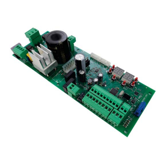
- Seite 5 P2.00 Connettori di collegamento encoder, Plug for encoder, limit switch and unlock microswitch connection Connettore scheda carica Display a 4 cifre e 6 tasti di Collegamento batterie batterie programmazione Batteries connection Plug for battery charger 4 digit display and 6 programming buttons Microcontrollore Collegamento...
- Seite 7 FUSIBILE FUSE FUSIBILE FUSE FUSIBILE FUSE Alimentazione Power supply BATTERY CHARGER +LAM +24V COS2 COS1 H93/RX22A/I RICEVITORE RADIO RADIO RECEIVER...
- Seite 8 Luce di cortesia Courtesy light 230Vac 100W marrone brown blue marrone brown FUSIBILE FUSE max 1A +LAM Spia cancello aperto Lampeggiante Open gate light Flashing light 24Vdc 3W 24Vdc max 25W +24V Apertura parziale Partial opening COS2 Passo passo Bordo sensibile 2 Step by step Safety edge 2 COS1...
- Seite 9 COLLEGAMENTO CON 1 COPPIA FOTOCELLULE SINCRONIZZABILI CONNECTION WITH 1 PAIR OF SYNCHRONOUS PHOCELLS USO RACCOMANDATO per fotocellule Serie F4ES - F4S RECOMMENDED USE for Series F4ES - F4S photocells MASTER 1 2 3 3 4 5...
- Seite 10 COLLEGAMENTO CON 2 COPPIE FOTOCELLULE SINCRONIZZABILI CONNECTION WITH 2 PAIRS OF SYNCHRONOUS PHOCELLS 3 4 5 1 2 3 MASTER SLAVE 1 1 2 3 4 5 1 2 3 USO RACCOMANDATO per fotocellule Serie F4ES - F4S RECOMMENDED USE for Series F4ES - F4S photocells nero black...
- Seite 11 TEST FOTOCELLULE · PHOTOCELLS TEST ( COLLEGAMENTO CON 1 COPPIA FOTOCELLULE SINCRONIZZABILI CONNECTION WITH 1 PAIR OF SYNCHRONOUS PHOCELLS USO RACCOMANDATO per fotocellule Serie F4ES - F4S RECOMMENDED USE for Series F4ES - F4S photocells MASTER 3 4 5 1 2 3...
- Seite 12 TEST FOTOCELLULE · PHOTOCELLS TEST ( COLLEGAMENTO CON 2 COPPIE FOTOCELLULE SINCRONIZZABILI CONNECTION WITH 2 PAIRS OF SYNCHRONOUS PHOCELLS USO RACCOMANDATO per fotocellule Serie F4ES - F4S RECOMMENDED USE for 1 2 3 1 2 3 4 5 Series F4ES - F4S photocells MASTER 1 2 3 4 5 1 2 3...
- Seite 13 BATTERY SAVING ( BATTERY SAVING + TEST FOTOCELLULE · PHOTOCELLS TEST ( COLLEGAMENTO CON 1 COPPIA FOTOCELLULE SINCRONIZZABILI CONNECTION WITH 1 PAIR OF SYNCHRONOUS PHOCELLS USO RACCOMANDATO per fotocellule Serie F4ES - F4S RECOMMENDED USE for Series F4ES - F4S photocells 1 2 3 1 2 3 4 5 MASTER...
- Seite 14 BATTERY SAVING ( BATTERY SAVING + TEST FOTOCELLULE · PHOTOCELLS TEST ( COLLEGAMENTO CON 2 COPPIE FOTOCELLULE SINCRONIZZABILI CONNECTION WITH 2 PAIRS OF SYNCHRONOUS PHOCELLS USO RACCOMANDATO per fotocellule Serie F4ES - F4S 1 2 3 4 5 1 2 3 RECOMMENDED USE for Series F4ES - F4S photocells MASTER...
- Seite 15 PR1 PR2...
- Seite 16 Nero/Black (26 Vac) Blu/Blue (19 Vac)
- Seite 17 BG30 High Speed Cavo motore Motor cable B72/BRAKE2...
- Seite 18 FINECORSA MECCANICO MECHANICAL LIMIT SWITCH FINECORSA MAGNETICO MAGNETIC LIMIT SWITCH...
- Seite 19 BATTERY B71/BCHP BATTERY CHARGER BATTERY FC SB PROG TEST SEC2 SEC1 10 11 12 13 14 15 16 17 18 TRANSFORMER BLACK FUSE T10A 5x20 2 x 12V 4,5Ah AGM Battery ONLY...
-
Seite 20: Avvertenze Generali
La mancata osservanza delle informazioni contenute nel presente manuale può dare luogo a infortuni personali o danni all’apparecchio. ROGER TECHNOLOGY declina qualsiasi responsabilità derivante da un uso improprio o diverso da quello per cui è destinato ed indicato nel presente manuale. - Seite 21 EN 12453 e EN 12445. ROGER TECHNOLOGY declina ogni responsabilità qualora vengano installati In caso sia attiva la funzione uomo presente dovrà essere cura dell’installatore in gomma, la velocità di chiusura del varco ed in generale tutti gli accorgimenti deve essere posto in una posizione che garantisca il controllo e il funzionamento di utilizzo 1 o 2).
-
Seite 22: Dichiarazione Ce Di Conformità
È necessario conservare queste istruzioni e trasmetterle ad eventuali subentranti nell’uso dell’impianto. Dichiarazione CE di Conformità (TV) DICHIARA che la centrale di comando B70/1DCHP è conforme ai requisiti essenziali e alle altre disposizioni – 2014/35/EU Direttiva LVD – 2014/53/EU Direttica RED... -
Seite 23: Simbologia
Simbolo per lo smaltimento del prodotto secondo la direttiva RAEE, vedere capitolo 22. Descrizione prodotto La centrale di comando digitale B70/1DCHP a 36 V utilizza il controllo di potenza motore in modalità sensored, Attenzione all’impostazione del parametro A1. Una errata impostazione può causare anomalie nel funzionamento dell’automazione. -
Seite 24: Aggiornamenti Versione P2
La somma degli assorbimenti di tutti gli accessori collegati non deve superare i dati di potenza massima indicati in tabella. I dati sono garantiti SOLO con accessori originali ROGER TECHNOLOGY. L'utilizzo di accessori non originali può causare malfunzionamenti. ROGER TECHNOLOGY declina ogni responsabilità per installazioni errate o non conformi. -
Seite 25: Descrizione Dei Collegamenti
Descrizione dei collegamenti Installazione tipo Le informazioni riportate in tabella sono indicative, è responsabilità dell'installatore alle loro caratteristiche tecniche. Cavo consigliato Alimentazione di rete. Cavo a doppio isolamento tipo H07RN-F 3x1,5 mm Fotocellula - Ricevitore F4ES/F4S Cavo 5x0,5 mm (massimo 20 m) Fotocellula - Trasmettitore F4ES/F4S Cavo 3x0,5 mm (massimo 20 m) -
Seite 26: Collegamenti Elettrici
±10%) Fusibile 5x20 T2A. Ingresso secondario del trasformatore per alimentazione motore 26 Vac (SEC1) e per alimentazione logica e periferiche 19 Vac (SEC2). NOTA: Il cablaggio è realizzato di fabbrica da ROGER TECHNOLOGY. SEC2 SEC1 X-Y-Z Collegamento B72/BRAKE/2 per versioni BG30 NOTA: I cablaggi sono realizzati di fabbrica da ROGER TECHNOLOGY. -
Seite 27: Comandi E Accessori
Comandi e accessori disabilitate modificando i parametri N.A. (Normalmente Aperto) . N.C. (Normalmente Chiuso). CONTATTO DESCRIZIONE 9(COR) Collegamento luce di cortesia (contatto puro) 230 Vac 100 W - 24 Vac/dc 40 W. NOTA: Prevedere un fusibile a protezione. 9(COR) • cancello sbloccato / anomalia nell'alimentazione da batteria (batteria in esaurimento); •... - Seite 28 CONTATTO DESCRIZIONE 24(ORO) 23(COM) Ingresso contatto temporizzato orologio (N.A.). Quando si attiva la funzione orologio il cancello apre e rimane aperto per il tempo programmato dall'orologio. Allo scadere del tempo programmato dal dispositivo esterno (orologio) il cancello chiude. Il funzionamento del comando è regolato dal parametro 25(AP) 23(COM) Ingresso comando di apertura (N.A.).
-
Seite 29: Tasti Funzione E Display
Tasti funzione e display TASTO DESCRIZIONE Parametro successivo Parametro precedente DOWN DOWN Incremento di 1 del valore del parametro Decremento di 1 del valore del PROG TEST parametro PROG Apprendimento della corsa TEST Attivazione modalità TEST • Premere i tasti UP e/o DOWN •... -
Seite 30: Modalità Visualizzazione Di Stato Comandi E Sicurezze
10.2 Modalità visualizzazione di stato comandi e sicurezze STATO DELLE SICUREZZE COS1 COS2 POWER STOP STATO DEI COMANDI: Le indicazioni dei comandi sono normalmente SPENTE. Si ACCENDONO accende il segmento PP). SEGMENTO COMANDO apre passo-passo chiude apertura parziale orologio STATO DELLE SICUREZZE: Le indicazioni delle sicurezze sono normalmente ACCESE. -
Seite 31: Modalità Test
10.3 Modalità TEST La modalità si attiva premendo il tasto TEST ad automazione ferma. Se il cancello è in movimento, il tasto TEST provoca uno STOP. La successiva pressione abilita la modalità di TEST. Il lampeggiante e la spia cancello aperto si accendono per un secondo. Il display visualizza a sinistra, per 5 s, lo stato dei comandi SOLO se attivi, (AP, CH, PP, PE, OR). -
Seite 32: Apprendimento Della Corsa
Apprendimento della corsa Per un corretto funzionamento, è necessario eseguire l’apprendimento della corsa. 11.1 Prima di procedere 1. Selezionare il modello dell’automazione installata con il parametro Motore HIGH SPEED Motore REVERSIBILE TIPO SELEZIONE MODELLO CONFIGURAZIONI MOTORE BG30/1600 BG30/2200 Vedi capitolo 14 "Parametri speciali per BG30/1000/HS High Speed"... -
Seite 33: Procedura Di Apprendimento
TEST VEDI CAPITOLO 16 e 17 1 click finchè ... TEST PROG VEDI PROCEDURA DI TEST AP P- APPRENDIMENTO CAP. 11.2 1 click CHIUSO 1 click Tener premuto Sì TEST VEDI PROCEDURA DI APPRENDIMENTO CAP. 11.2 1 click 11.2 Procedura di apprendimento PROG FO FO TO TO AP P-... -
Seite 34: Indice Dei Parametri
Indice dei parametri PARAM. VALORE DI DESCRIZIONE PAGINA FABBRICA vedi Cap. 13 Selezione modello automazione Richiusura automatica dopo il tempo di pausa (da cancello completamente aperto) Selezione funzionamento comando passo-passo (PP) Prelampeggio Funzione condominiale sul comando di apertura parziale (PED) Abilitazione funzione a uomo presente Spia cancello aperto/funzione test fotocellule e "battery saving"... - Seite 35 PARAM. VALORE DI DESCRIZIONE PAGINA FABBRICA Regolazione dello spazio di arresto del motore Selezione della posizione di installazione del motore rispetto al varco, vista lato interno Selezione modalità di funzionamento luci di cortesia Abilitazione della chiusura/apertura garantita Regolazione tempo di attivazione della chiusura/apertura garantita Selezione gestione funzionamento a batteria Selezione delle limitazioni nel funzionamento a batteria Selezione del tipo di batteria e riduzione dei consumi...
-
Seite 36: Menù Parametri
Menù parametri VALORE DEL Selezione modello automazione ATTENZIONE! Una errata impostazione può causare anomalie nel funzionamento dell’automazione. NOTA reimpostato manualmente. BG30/1600 BG30/2200 BG30/1000/HS speciali per High Speed). BG30/1400/R BG30/1800/HS speciali per High Speed). BG30/1500/HS speciali per High Speed). Richiusura automatica dopo il tempo di pausa (da cancello completamente aperto) Disabilitata. -
Seite 37: Funzione Condominiale Sul Comando Di Apertura Parziale (Ped)
Funzione condominiale sul comando di apertura parziale (PED) Abilitato. Durante l’apertura il comando di apertura parziale (PED) viene ignorato. Abilitazione funzione a uomo presente Disabilitato. Abilitato. Il cancello funziona tenendo premuti i comandi apre (AP) o chiude (CH). Al rilascio del comando il can- cello si ferma. -
Seite 38: Regolazione Accelerazione Alla Partenza In Apertura (E Chiusura Per
Abilitazione gestione apertura con esclusione della richiusura automatica Se abilitata, l'esclusione della richiusura automatica vale solo per il comando selezionato dal parametro. Esempio se si imposta , dopo un comando AP la richiusura automatica è esclusa, mentre dopo i comandi PP e PED la richiusura automatica si attiva. -
Seite 39: Regolazione Della Coppia Motore Durante La Fase Di Recupero Posizione
Regolazione della coppia motore durante la fase di recupero posizione Regolare con il parametro la coppia motore se in fase di recupero posizione i valori impostati ai parametri fossero inadeguati per garantire al cancello di completare la manovra. Se la fase di recupero posizione non si completa, il cancello non riprende il suo normale funzionamento. L’intervento del rilevamento ostacolo è... -
Seite 40: Impostazione Modalità Di Funzionamento Della Fotocellula In Apertura (Ft2)
Impostazione modalità di funzionamento della fotocellula in apertura (FT2) tamente. tinua ad aprire. INVERSIONE RITARDATA. Con fotocellula oscurata il cancello si ferma. Liberata la fotocellula il cancello chiude. Impostazione modalità di funzionamento della fotocellula in chiusura (FT2) a chiudere. INVERSIONE RITARDATA. Con fotocellula oscurata il cancello si ferma. Liberata la fotocellula il cancello apre. Modalità... -
Seite 41: Selezione Modalità Di Funzionamento Luci Di Cortesia
NOTA NOTA PASSO PASSO. APERTURA PARZIALE. APERTURA. CHIUSURA. STOP. attivo. Il parametro viene ignorato. Luce di cortesia passo-passo (PP). L’uscita COR viene gestita dal radiocomando. Il radiocomando accende-spegne la luce di cortesia. Il parametro viene ignorato. PASSO PASSO con conferma di sicurezza APERTURA PARZIALE con conferma di sicurezza APERTURA con conferma di sicurezza CHIUSURA con conferma di sicurezza... -
Seite 42: Regolazione Tempo Di Attivazione Della Chiusura/Apertura Garantita
Regolazione tempo di attivazione della chiusura/apertura garantita NOTA: Il parametro non è visibile se il parametro Da 2 a 90 s di attesa. Da 2 a 9 min di attesa. Selezione gestione funzionamento a batteria Impostando un valore diverso da si abilita un controllo sul livello di tensione della batteria. -
Seite 43: Versione Hw
NOTA Versione HW Anno di produzione Settimana di produzione Numero seriale Versione FW Visualizzazione contatore manovre Il numero è composto dai valori dei parametri da moltiplicato per 100. NOTA Manovre eseguite x100 = 1.234.500 manovre Visualizzazione contatore ore manovra Il numero è composto dai valori dei parametri da NOTA Ore manovra = 123 ore... -
Seite 44: Parametri Speciali Serie High Speed
Qui di seguito sono indicati i parametri aggiuntivi relativi all'attivazione della tecnologia High Speed. Selezione modello automazione Il parametro è impostato di fabbrica da ROGER TECHNOLOGY. ATTENZIONE! Il valore di fabbrica e già impostato allo scopo di utilizzare il motore nella versione ad alta velocità... -
Seite 45: Parametri Speciali Serie Bg30/1400/R
Nel funzionamento prolungato a batteria, pertanto, si potrà avere una riduzione dell'autonomia. spostamento del cancello di più di 3 cm, la centrale avvierà una procedura di recupero posizione (vedi capitolo 20). NOTA Selezione modello automazione Il parametro è impostato di fabbrica da ROGER TECHNOLOGY. ATTENZIONE NOTA manualmente. -
Seite 46: Segnalazione Degli Ingressi Di Sicurezza E Dei Comandi (Modalità Test)
Segnalazione degli ingressi di sicurezza e dei comandi (modalità TEST) DISPLAY POSSIBILE CAUSA INTERVENTO DA SOFTWARE INTERVENTO TRADIZIONALE La maniglia di sblocco è aperta. Chiudere la maniglia di sblocco e girare la chiave in posizione di chiu- (Sb) sura. di sblocco. Contatto STOP di sicurezza Installare un pulsante di STOP (N.C.) aperto. -
Seite 47: Segnalazione Allarmi E Anomalie
Segnalazione allarmi e anomalie SEGNALAZIONE PROBLEMA POSSIBILE CAUSA INTERVENTO ALLARME LED POWER spento LED POWER spento Fusibili bruciati. Sostituire il fusibile. Si raccomanda di estrarre e reinserire il fusibile sola- mente in assenza di tensione di rete. Anomalia nella tensione Togliere alimentazione, attendere 10 s e ridare ali- di alimentazione di in- mentazione. - Seite 48 SEGNALAZIONE PROBLEMA POSSIBILE CAUSA INTERVENTO ALLARME Premere il tasto TEST, se la segnalazione di errore dell’encoder. persiste, sostituire l’encoder. (EnE5) Alimentazione da rete Nel caso ci sia presenza di sporco, umidità, insetti o altro, togliere l’alimentazione e pulire l'encoder e la scheda.
-
Seite 49: Diagnostica - Modalità Info
TEST PER USCIRE 1 click DALLA MODALITA’ x5 s B70/1DCHP. Dalla modalità “Visualizzazione comandi e sicurezze” e con motore fermo, premere per 5 s il tasto TEST. Parametro Funzione totale. = motore installato a sinistra = motore installato a destra assorbita. -
Seite 50: Sblocco Meccanico
Sblocco meccanico In caso di guasto o in mancanza di tensione, è possibile sbloccare il cancello e movimentarlo a mano. Per ulteriori informazioni consultare l'operazione di blocco/sblocco sul manuale d'uso dell'automazione. Se si sblocca il cancello con la centralina alimentata, sul display appare lampeggiante. -
Seite 51: Messa In Funzione
Informazioni aggiuntive e contatti Tutti i diritti relativi alla presente pubblicazione sono di proprietà esclusiva di ROGER TECHNOLOGY. Il formato digitale (PDF) e tutti gli eventuali aggiornamenti futuri, sono disponibili nell’area riservata del nostro sito SERVIZIO CLIENTI ROGER TECHNOLOGY:... -
Seite 52: General Safety Precautions
ROGER TECHNOLOGY is not liable for failure to observe the good practices occur during use. The safety devices (photocells, sensing edges, emergency stops, etc.) must... - Seite 53 The installer is required to measure impact forces and select on the control unit the appropriate speed and torque values to ensure that the door or gate ROGER TECHNOLOGY cannot be held responsible for any damage or injury caused by the installation of incompatible components which compromise the safety and correct operation of the device.
-
Seite 54: Declaration Ce Of Conformity
Declaration CE of Conformity The undersigned Dino Florian, legal representative of Roger Technology - Via Botticelli 8, 31021 Mogliano V.to (TV) DECLARES that the B70/1DCHP digital control unit is compliant with the provisions established by – 2014/35/EU LVD Standard – 2014/53/EU RED Standard... -
Seite 55: Symbols
22. Product description The B70/1DCHP 36 V digital control unit uses a high resolution encoder for the sensored power control of ROGER sliding gate leaf automation systems. Ensure that the parameter A1 is set correctly. If this parameter is not set correctly, the automation system may not function properly. -
Seite 56: Updates Of Version P2
The total of the absorption values of all the accessories connected must not exceed the maximum power values shown in the table. The values are guaranteed with original ROGER TECHNOLOGY accessories ONLY. The use of non-original accessories may lead to malfunctioning. ROGER TECHNOLOGY declines all responsibility for incorrect or non-conforming installations. -
Seite 57: Description Of Connections
Description of connections To access the control connection terminal board, remove the motor cover as shown in Figure 2-3-4-5 shows connection diagrams for connecting mains voltage to the motor control unit Typical installation It is the installer's responsibility to verify the adequacy of the cables in relation to the devices used in the installation and their technical characteristics. -
Seite 58: Electrical Connections
DESCRIPTION Fuse 5x20 T2A. Secondary transformer input for 26 V AC motor power (SEC1) and for 19 V power to logical control and peripheral devices (SEC2). N.B.: Ready wired in factory by ROGER TECHNOLOGY. SEC2 SEC1 X-Y-Z Connection to ROGER brushless motor. -
Seite 59: Commands And Accessories
17(ST) 16(COM) STOP command input (NC). The current manoeuvre is arrested if the safety contact opens. N.B.: the controller is supplied with this contact already jumpered by ROGER TECHNOLOGY. 21(ANT) Antenna connector for slot-in radio receiver board. N.B. 24(ORO) - Seite 60 Adjust the limit switches so that, once triggered, the gate stops slightly before it reaches the mechanical stop. IMPORTANT to the limit switches. N.B.: Ready wired in factory by ROGER TECHNOLOGY. Connector (N.C.) for connecting release contact. If the motor release handle is opened, the gate stops and no command signals are accepted.
-
Seite 61: Function Buttons And Display
Function buttons and display BUTTON DESCRIPTION Next parameter Previous parameter DOWN DOWN Increase value of parameter by 1 Decrease value of parameter by 1 PROG Travel acquisition PROG TEST TEST Activate TEST mode • Press the UP and/or DOWN buttons to view the parameter you intend to modify. •... -
Seite 62: Command And Safety Device Status Display Mode
10.2 Command and safety device status display mode SAFETY DEVICE STATUS COS1 COS2 POWER STOP COMMAND STATUS: The command status indicators on the display are normally OFF. illuminates). SEGMENT COMMAND open step-by-step mode close partial opening SAFETY DEVICE STATUS: The safety device status indicators ON the display . If an indicator is OFF, the relative device is in alarm state or is not connected. -
Seite 63: Test Mode
10.3 TEST mode To activate the mode, press the TEST button with the automatic door system at rest. If the gate is moving, pressing TEST stops the gate. Pressing the button again enables TEST mode. safety device is activated. The command signal status is shown on the left hand side of the display for 5 seconds, ONLY when the respective command signal is active (AP, CH, PP, PE, OR). -
Seite 64: Travel Acquisition
Travel acquisition For the system to function correctly, the gate travel must be acquired by the control. 11.1 Before starting 1. Select the automation system model installed with the parameter HIGH SPEED Motor REVERSIBLE Motor MOTOR SELECTION MODEL CONFIGURATIONS TYPE BG30/1600 BG30/2200 see chapter 14 "Special Parameters for... -
Seite 65: Acquisition Procedure
TEST SEE CHAPTER 16 and 17 1 click Until ... TEST PROG ACQUISITION TEST AP P- PROCEDURE CHAP. 11.2 1 click CLOSE 1 click Press and hold on TEST ACQUISITION PROCEDURE CHAP. 11.2 1 click 11.2 Acquisition procedure: PROG FO TO AP P- PH A5 PH A5... -
Seite 66: Parameter's Index
Parameter's index FACTORY PARAM. DESCRIPTION PAGE VALUE Selecting automation system model see chap. 13 Automatic closure after pause time (from gate completely open) Automatic gate closing after mains power outage Selecting step mode control function (PP) Condominium function for partial open command (PED) Enabling operator present function. -
Seite 67: Param
FACTORY PARAM. DESCRIPTION PAGE VALUE Selecting courtesy light mode Enable safeguarded gate closure/opening. Setting safeguarded closure/opening activation time Selection of the battery operation management Selection of the battery operation limitations Selection of the battery type and consumption reduction Restoring factory default values HW version. -
Seite 68: Parameter Menu
Parameter menu VALUE Selecting automation system model WARNING! If this parameter is not set correctly, the automation system may not function properly. N.B.: in the event of a reset to restore the default parameters, this parameter must be set again manually. BG30/1600 BG30/2200 BG30/1000/HS... -
Seite 69: Condominium Function For Partial Open Command (Ped)
Condominium function for partial open command (PED) Enabled. Partial commands are ignored during gate opening. Enabling operator present function Disabled. Enabled. The open (AP) or close (CH) button must be pressed continuously to operate the gate. The gate stops when the button is released. Gate open indicator / photocell test function and “battery saving”... -
Seite 70: Enabling Of Management For Opening With Automatic Re-Closure Exclusion
Enabling of management for opening with automatic re-closure exclusion If enabled, the exclusion of automatic re-closure only applies for the command selected via the parameter. For , automatic re-closure is excluded following an AP command, but it is activated following a PP or PED command. -
Seite 71: Setting Motor Torque During Position Recovery
Setting motor torque during position recovery Adjust motor torque with parameter if, during position recovery, the values set with parameters If position recovery is not completed, normal gate operation will not be resumed. The response of the obstacle detection system depends solely on the values set for parameters The response of the obstacle detection system depends on the values set for parameters and on the maximum current value stored during travel acquisition. -
Seite 72: Setting Photocell Mode During Gate Closing (Ft2)
Setting photocell mode during gate opening (FT2) STOP. The gate stops and remains stationary until the next command is received. photocell is cleared. DELAYED REVERSE. The gate stops if the photocell is obstructed. The gate closes when the photocell is cleared. Setting photocell mode during gate closing (FT2) STOP. - Seite 73 PARTIAL OPENING OPENING CLOSING. STOP. Courtesy light. The output COR is managed from the remote control. The light remains lit as long as the remote control is active. The parameter is ignored. Courtesy light in step mode (PP). The output COR is managed from the remote control. The remote control turns the courtesy light on and off.
- Seite 74 Setting safeguarded closure/opening activation time N.B.: this parameter is not visible if the value of parameter Wait time settable from 2 to 90 s. Wait time settable from 2 to 9 min. Selection of the battery operation management Setting a value different than selected via parameter and an error alert can be activated through the COR output via parameter The control unit always accepts commands until the battery is completely exhausted.
-
Seite 75: Changing Password
N.B. HW version. Year of manufacture. Week of manufacture. Example Serial number. FW version. View manoeuvre counter The number consists of the values of the parameters from multiplied by 100. N.B. Manoeuvres performed. x100 = 1.234.500 manoeuvres. View manoeuvre hour counter The number consists of the values of the parameters from N.B. -
Seite 76: Bg30/1800/Hs Series
Special parameters for HIGH SPEED series applications. conventional system, and allows independent management of speed, acceleration, deceleration and the safety devices used in the system. Note: As the mechanics of the gate is unknown, to guarantee the maximum safety of the installation, we recommended to use sensitive edges. -
Seite 77: Special Parameters For Bg30/1400/R Series
Special parameters for BG30/1400/R series even in the event of power failure. The control unit allows independent management of speed, acceleration, deceleration and the safety devices used in the system. force to impede manual movement of the gate. As a result, prolonged operation may drain the battery when operating under battery power. than 3 cm is detected, the control unit initiates a position recovery procedure (see chapter 20). -
Seite 78: Safety Input And Command Status (Test Mode)
Safety input and command status (TEST mode) DISPLAY POSSIBLE CAUSE ACTION BY SOFTWARE PHYSICAL CORRECTIVE ACTION The release handle is open. Close the release handle and turn the (Sb) nected correctly. The safety STOP contact is open. Install a STOP button (NC) or jumper Sensing edge COS1 not connected Set the parameter Jumper contact COS1 with contact... -
Seite 79: Alarms And Faults
Alarms and faults PROBLEM ALARM POSSIBLE CAUSE ACTION LED POWER off No power. LED POWER off Fuses blown. Replace fuses. Always disconnect from mains power before removing fuses. Input mains power voltage fault. Disconnect from mains power, wait 10 seconds then reconnect to the mains and switch on. - Seite 80 PROBLEM ALARM POSSIBLE CAUSE ACTION Encoder malfunction. Press TEST button. Replace the encoder if the problem persists. (EnE5) If the unit contains dirt, moisture, insects or other foreign matter, disconnect from mains power and clean the board and the encoder. Replace the en- coder if the problem persists.
- Seite 81 INFO MODE x5 s INFO mode may be used to view certain parameters measured by the B70/1DCHP controller. Press and hold the TEST button for 5 seconds from the “View command signals and safety devices” mode with the motor stationary.
-
Seite 82: Mechanical Release
Mechanical release In the event of a fault or mains power loss, the gate may be released and opened manually. For further information, refer to the locking/release operation in the manual of the automation system. If the gate releases with the controller unit powered, the message When the release system is restored to the normal operating position, if the gate is not completely open or completely closed the next time a command is received, the control initiates a position recovery procedure (see chapter 20). -
Seite 83: Start-Up
Warning! Some parts of this product may contain substances that are harmful to the if disposed of incorrectly. Additional information and contact details ROGER TECHNOLOGY is the exclusive proprietor holder of all rights regarding this publication. scanning or any alterations to this document are prohibited without express prior authorised from by ROGER TECHNOLOGY. -
Seite 84: Allgemeine Sicherheitshinweise
Übereinstimmung der geltenden Richtlinien ausgeführt vorzunehmen, um Sicherheits- und Schutzzonen zu schaffen bzw. alle ROGER TECHNOLOGY ist weder für die Einhaltung der fachgerechten Die Sicherheitseinrichtungen (Fotozellen, Sicherheitsleisten, Notstopps den geltenden Vorschriften und Richtlinien, den fachgerechten Kriterien, der von der motorisierten Tür oder dem Tor ausgehen. - Seite 85 Gefahren verursachen. Sicherheitsleisten am beweglichen Teil installieren. der Normen EN 12604 und EN 12453 erfüllt und gegebenenfalls auch überprüft werden müssen. bzw. das motorisierte Tor die von den Richtlinien EN 12453 und EN 12445 darauf hingewiesen, dass die Steuereinrichtung bei einer festen Anordnung 1 oder 2).
-
Seite 86: Konformitätserklärung
Anlage übergeben werden. Konformitätserklärung Der Unterzeichnende Dino Florian, gesetzlicher Vertreter von Roger Technology - Via Botticelli 8, 31021 Mogliano V.to (TV) ERKLÄRT, dass die Steuerung B70/1DCHP mit den von den folgenden Gemeinschaftsrichtlinien – 2014/35/EU LVD Richtlinie – 2014/53/EU RED Richtlinie –... -
Seite 87: Symbole
Es muss auf die Einstellung des Parameters A1 geachtet werden. Eine falsche Einstellung kann Funktionsstörungen des Antriebs verursachen. werden, ab. Wir empfehlen die Verwendung von Zubehör, Steuer- und Sicherheitsvorrichtungen ROGER TECHNOLOGY. F4ES oder F4S zu installieren. Für weitere Informationen, siehe die Installationsanleitung der Automatisierung... -
Seite 88: Aktualisierungen Version P2
Aktualisierungen Version P2.00 Technische Daten des Produkts BG30/1603 BG30/2203 BG30/1003/HS BG30/1004/HS BG30/1404/R BG30/1504/HS BG30/1804/HS BG30/1604 BG30/2204 VERSORGUNGSSPANNUNG 230 V ± 10% 50 Hz (115 V ± 10% 50/60 Hz) MAXIMAL VOM STROMNETZ 180 W 190 W 200 W 190 W 240 W 230 W AUFGENOMMENE LEISTUNG... -
Seite 89: Beschreibung Der Anschlüsse
Beschreibung der Anschlüsse wie auf Abbildung 1 In Abbildung 2-3-4-5 Art der Installation überprüfen. Empfohlene Kabel Stromversorgung Kabel mit mit doppelt isolierten Typ H07RN-F 3x1,5 mm F4ES/F4S Kabel 5x0,5 mm 20 m) Sender F4ES/F4S Kabel 3x0,5 mm 20 m) R92/LED24 - FIFTHY/24 Kabel 2x1 mm 10 m) Stromversorgung 24V dc... -
Seite 90: Elektrische Anschlüsse
Leitungen des Zubehörs (24 V) getrennt sind. BESCHREIBUNG Spannung Netzanschluss 230 Vac ±10% (115 Vac ±10%) . Sicherung 5x20 T2A. ANMERKUNG: Die Verkabelung erfolgt werkseitig von ROGER TECHNOLOGY. SEC2 SEC1 X-Y-Z Anschluss B72/BRAKE/2 für Ausführungen BG30 High Speed (Siehe Abb.13). -
Seite 91: Befehle Und Zubehör
Befehle und Zubehör werden. KONTAKT BESCHREIBUNG 9(COR) Ausgang für Anschluss an die Zugangsbeleuchtung dc 40 W. HINWEIS: Eine Schutzsicherung vorsehen. 9(COR) • • gesteuert. eingestellt werden. 10(+SC) 11(COM) Anschluss Kontrollleuchte Tor offen 24 Vdc 3 W. geregelt. 10(+SC) 11(COM) Den Parameter Es ist außerdem möglich, die Stromversorgung aller externen Vorrichtungen anzuschließen, um oder einstellen. - Seite 92 KONTAKT BESCHREIBUNG 24(ORO) 23(COM) das Tor schließt sich. geregelt. 25(AP) 23(COM) ACHTUNG der bei Loslassen des Öffnungsbefehls. 26(CH) 23(COM) Eingang Schließbefehl (Schließer). 27(PP) 23(COM) geregelt. 28(PED) 23(COM) 29(+24V) 30(COM) Siehe technische Daten. Versorgungsanschluss B72/BRAKE/2 für Ausführungen BG30 High Speed. 31(LAM) 30(COM) (24 Vdc - Einschaltdauer 50%).
-
Seite 93: Funktionstasten Und Display
Funktionstasten und Display TASTE BESCHREIBUNG Vorangehender Parameter DOWN DOWN Erhöhung des Parameterwerts um 1 Verringerung des Parameterwerts um 1 PROG Programmierung des Torlaufs PROG TEST TEST • Die Tasten UP und/oder DOWN • + und - • Wenn man die Taste + oder die Taste - •... -
Seite 94: Anzeigemodus Des Status Von Befehlen Und Sicherheitseinrichtungen
10.2 Anzeigemodus des Status von Befehlen und Sicherheitseinrichtungen STATUS DER SICHER- HEITSEINRICHTUNGEN COS1 COS2 POWER STOP STATUS DER BEFEHLE: sich das Segment PP ein). SEGMENTE BEFEHLE öffnet Schrittbetrieb schließt Teilöffnung STATUS DER SICHERHEITSEINRICHTUNGEN: Die Anzeigen der Sicherheitseinrichtungen sind normalerweise eingeschaltet. Sollten sie ausgeschaltet sein bedeutet dies, dass sie in Alarm oder nicht angeschlossen sind. -
Seite 95: Test-Modus
10.3 TEST-Modus Das Display zeigt auf der rechten Seite den Status der Wenn das Tor ganz geöffnet oder ganz geschlossen ist, erscheint am Display oder , das weist darauf hin, dass das Schwingtor sich am Öffnungsendschalter und am Schließungsendschalter (Sb) Entriegelungsgriff oder Schloss offen. -
Seite 96: Einlernen Des Torlaufs
Einlernen des Torlaufs 11.1 Zunächst LEGENDE HIGH SPEED Motor UMKEHRENDER Motor AUSWAHL MODELL KONFIGURATIONEN MOTOR BG30/1600 BG30/2200 (siehe Kapitel 14 "Sonderparameter für BG30/1000/HS High Speed). (siehe Kapitel 15 "Sonderparameter für BG30/1400/R UMKEHRENDER Motor). (siehe Kapitel 14 "Sonderparameter für BG30/1800/HS High Speed). (siehe Kapitel 14 "Sonderparameter für BG30/1500/HS High Speed). -
Seite 97: Einlernverfahren
TEST Siehe Kapitel 16 und 17 1 Klick Bis ... TEST PROG EINLERNVERFAHREN TEST AP P- Kap. 11.2 1 Klick GESCHLOSSEN 1 Klick Drücken Sì TEST EINLERNVERFAHREN Kap. 11.2 1 Klick 11.2 Einlernverfahren PROG FO TO AP P- PH A5 PH A5 AU to x4 s... -
Seite 98: Index Der Parameter
Index der Parameter STANDARD- PARAM. BESCHREIBUNG SEITE WERTE Auswahl des Antriebsmodells Siehe Kapitel 13 geöffnetem Tor) saving” Einstellung der Verlangsamung beim Öffnen (und Schließen für BG30/1600- BG30/2200) Einstellung der Verlangsamung beim Schließen (nur für High Speed und Umkehrender Motor) Einstellung Teilöffnung (%) Art der Signalisierung durch COR-Ausgang Einstellung der automatischen Schließzeit erneuten Schließung. - Seite 99 STANDARD- PARAM. BESCHREIBUNG SEITE WERTE (Ansicht von der Innenseite) HW-Version Herstellungsjahr Herstellungswoche Seriennummer FW-Version Passwort...
-
Seite 100: Menü Parameter
Menü Parameter WERT DES Auswahl des Antriebsmodells ACHTUNG! ANMERKUNG: von Hand neu eingestellt werden. BG30/1600 BG30/2200 BG30/1000/HS parameter für High Speed). BG30/1400/R BG30/1800/HS parameter für High Speed). BG30/1500/HS parameter für High Speed). Automatische Schließung nach Auslösen nach der Pausenzeit (bei vollstän- dig geöffnetem Tor) Versuche bleibt das Tor offen. -
Seite 101: Einstellung Des Annäherungswegs An Den Schließungsendschalter Mit Konstanter Geschwindigkeit
Wohnanlagebetrieb auf Befehl zur Teilöffnung (PED) Aktivieren des Totmannbetriebs. Kontrollleuchte Schwingtor offen / Funktion Lichtschrankentest und “battery saving” und wenn das Tor geöffnet ist. Wenn das Tor in einer Zwischenposition stillsteht, schaltet sich die Kontrollleuchte zweimal alle 15 s aus. einstellen, wenn der Ausgang SC einstellen, wenn der Ausgang SC SC angesch-... -
Seite 102: Einstellung Motordrehmoment
Aktivierung der Öffnungsverwaltung mit Deaktivierung der automatischen erneuten Schließung. HINWEIS stoppen-öffnen. Einstellung der Umkehrzeit nach Auslösung der Sicherheitsleiste oder Erken- nung von Hindernissen (Quetschschutz). von 0 bis 60 s. Einstellung Motordrehmoment verringern. ANMERKUNG Installation geeignet sind. Empfohlene Einstellung für die Regelung der einwirkenden Kräfte. bei 70% des maximalen für eine Auslösezeit von 1 s. -
Seite 103: Einstellung Des Motordrehmoments Während Der Korrektur Der Position
Einstellung des Motordrehmoments während der Korrektur der Position Parametern auf. eingestellten Werte geregelt. stroms geregelt, der beim Einlernen des Torlaufs gespeichert wurde. Einstellung Öffnungsgeschwindigkeit und Schließungsgeschwindigkeit ANMERKUNG: Teile unterteilt. Siehe Kapitel 14 und 15. 01= 6 m/min ... 10= Einstellung der konstanten Annäherungsgeschwindigkeit am Ende der Bewegung Weg ist von den Parametern geregelt. -
Seite 104: Auswahl Des Installationsorts Des Motors Im Vergleich Zum Durchgang (Ansicht Von Der Innenseite)
Einstellung Funktionsweise der Lichtschranke beim Öffnen (FT2) das Tor sich. Einstellung Funktionsweise der Lichtschranke beim Schließen (FT2) Tor sich. Funktionsweise der Lichtschranke (FT2) bei geschlossenem Tor Der Parameter ist nicht sichtbar, wenn man oder einstellt. Aktivierung Schließbefehl 6 s nach Auslösen der Lichtschranke (FT1-FT2) Der Parameter ist nicht sichtbar, wenn man oder einstellt. -
Seite 105: Auswahl Funktionsweise Zugangsbeleuchtung
HINWEIS HINWEIS TEILÖFFNUNG ÖFFNUNG SCHLIESSUNG. STOPP. Zugangsbeleuchtung. Der Ausgang COR wird von der Fernbedienung gesteuert. Das Licht bleibt eingeschaltet, wird ignoriert. Zugangsbeleuchtung Schrittbetrieb (PP). Der Ausgang COR wird von der Fernbedienung gesteuert. Die Fernbedienung schaltet die Zugangsbeleuchtung ein-aus. Der Parameter wird ignoriert. -
Seite 106: Einstellung Aktivierungszeit Der Garantierten Schließung/Öffnung
Einstellung Aktivierungszeit der garantierten Schließung/Öffnung HINWEIS: Der Parameter wird nicht angezeigt, wenn der Parameter ist. von 2 bis 90 s Wartezeit Auswahl der Verwaltung im Batteriebetrieb Wenn ein anderer Wert als Parameter Auswahl der Einschränkungen im Batteriebetrieb. ANMERKUNG nicht ist. entsprechend eingestellt sind). - Seite 107 Kennnummer Die Kennnummer besteht aus den Werten der Parameter von n0 bis n6. ANMERKUNG: Die in der Tabelle angegebenen Werte dienen nur zur Veranschaulichung. HW-Version. Herstellungsjahr. Herstellungswoche. Seriennummer. FW-Version. Anzeige Bewegungszähler Die Zahl besteht aus den Werten der Parameter von multipliziert mit 100.
-
Seite 108: Sonderparameter Für Die Baureihe High Speed
Sonderparameter für die Baureihe HIGH SPEED Wohnbereich vorbehalten sind. Sicherheiten getrennt zu verwalten. ANMERKUNG: Die Mechanik des Tors nicht bekannt ist, um die maximale Sicherheit des Betriebes zu garantieren, empfehlen wir die Sicherheitsleiste zu installieren. Auswahl des Antriebsmodells ACHTUNG! ANMERKUNG: des Parameters von Hand neu eingestellt werden. -
Seite 109: Sonderparameter Für Die Baureihe Bg30/1400/R
Sonderparameter für die Baureihe BG30/1400/R Kapitel 20). HINWEIS: Auswahl des Antriebsmodells ACHTUNG! ANMERKUNG: des Parameters von Hand neu eingestellt werden. BG30/1400/R - IRREVERSIBLER Motor für Flügel mit max 1400 kg. Einstellung der Verlangsamung beim Öffnen Einstellung der Verlangsamung beim Schließen Endschalter. -
Seite 110: Meldung Der Sicherheitseingänge Und Der Befehle (Test-Modus)
Meldung der Sicherheitseingänge und der Befehle (TEST- Modus) MASSNAHME ÜBER HERKÖMMLICHE DISPLAY MÖGLICHE URSACHE SOFTWARE MASSNAHME Der Entriegelungsgriff ist Den Entriegelungsgriff schließen und den geöffnet. Schüssel in Schließstellung drehen. (Sb) überprüfen. Eine STOPP-Taste (Öffner) installieren geöffnet. Sicherheitsleiste COS1 Falls nicht benutzt oder man sie Falls nicht benutzt oder man sie aus- nicht oder falsch ange- ausschließen will, den Parameter... -
Seite 111: Meldung Von Alarmen Und Störungen
Meldung von Alarmen und Störungen PROBLEM ALARMMELDUNG MÖGLICHE URSACHE BETRIEB ausgeschaltet Keine Stromversorgung. LED POWER ausgeschaltet Sicherung durchgebrannt. Sicherung ersetzen. LED POWER Die Sicherung nur bei ausgeschalteter Netzspan- nung herausziehen. Störung der Eingangsspan- Die Netzspannung ausschalten, 10 s warten und nung. - Seite 112 PROBLEM ALARMMELDUNG MÖGLICHE URSACHE BETRIEB (EnE5) coders. bestehen bleibt, den Encoder austauschen. Stromversor- gung oder anderem, die Stromversorgung trennen und die Karte sowie den Encoder reinigen. Wenn das Problem weiter besteht, den Encoder austauschen. Das Tor öffnet oder Rechenfehler des Encoders. Das Einlernverfahren wiederholen. schließt sich nicht.
-
Seite 113: Diagnostik - Betriebsart Info
TEST AUS DER TEST BESTRIEBSART 1 Klick ZU GEHEN x5 s B70/1DCHP angezeigt. Parameter Funktion Anzeige erfassen. Netzspannung = 230 Vac (Nennspannung), bUS = Netzspannung = 207 Vac (-10%), bUS = Netzspannung = 253 Vac (+10%), bUS = abzugebenden Strom. -
Seite 114: Mechanische Entriegelung
Mechanische Entriegelung Für weitere Informationen, siehe die Verriegelungs-/Entriegelungsvorgänge im Gebrauchshandbuch der Automatisierung BG30. Modus zur Korrektur der Position • • 1,5 s ausgeschaltet). • Achtung • Nach einem Spannungsausfall oder einer mechanischen Entriegelung startet die Steuereinheit, wenn das Tor und/ oder BG30/1400/R. -
Seite 115: Inbetriebnahme
Vorschriften vorgesehen sind. Achtung! Zusätzliche Informationen und Kontakte Alle Rechte bezüglich dieser Veröffentlichung sind ausschließliches Eigentum von ROGER TECHNOLOGY. Kopien, Scannen, Überarbeitungen oder Änderungen sind ohne vorherige schriftliche Zustimmung durch ROGER unserer Website www.rogertechnology.com/B2B auf der Seite Self Service zur Verfügung. -
Seite 116: Consignes Générales De Sécurité
Lire les instructions avec beaucoup d'attention avant d'installer le produit. ne pas utiliser le produit et s'adresser exclusivement à du personnel professionnel ROGER TECHNOLOGY n'est pas responsable du non-respect de la bonne technique se produire dans l’utilisation. vigueur, des critères de la bonne technique, du local d'installation, de la logique de fonctionnement du système et des forces produites par la porte ou le portail... - Seite 117 toute circonstance. sur la centrale de commande les valeurs de la vitesse et du couple qui permettent à EN 12445. et le fonctionnement de l’automatisme et que le type de commande et d'utilisation personnes qui se trouvent dans le rayon d'action des parties en mouvement ; les zones dangereuses.
-
Seite 118: Déclaration De Conformité Ce
Déclaration de conformité CE Roger Technology - Via Botticelli 8, 31021 Mogliano V.to (TV) DÉCLARE que la centrale de commande B70/1DCHP – 2014/35/EU Directive LVD – 2014/53/EU Directive RED – 2011/65/CE Directive RoHS... -
Seite 119: Symboles
Symboles Danger général. d'attention. Danger par tension dangereuse. doit faire beaucoup d'attention à des tensions dangereuses. Danger par surfaces chaudes. Informations utiles Il signale des informations utiles pour l'installation. Consultation des instructions d'installation et d'utilisation Il signale l'obligation de consulter le manuel ou le document Point de branchement de la mise à... -
Seite 120: Mises À Jour Version P2
Mises à jour version P2.00 2. Ajout d’un connecteur pour brancher le module WiFi (pour une utilisation future) Caractéristiques techniques produit BG30/1603 BG30/2203 BG30/1003/HS BG30/1404/R BG30/1504/HS BG30/1804/HS BG30/1604 BG30/2204 BG30/1004/HS TENSION D’ALIMENTATION 230 V ± 10% 50 Hz (115 V ±... -
Seite 121: Description Des Raccordements
Description des raccordements Dans la Installation type Câble conseillé Alimentation Câble à double isolation type H07RN-F 3x1,5 mm F4ES/F4S Câble 5x0,5 mm (max 20 m) F4ES/F4S Câble 3x0,5 mm (max 20 m) Clignotant à LED R92/LED24 - FIFTHY/24 Câble 2x1 mm (max 10 m) Alimentation 24 Vdc Antenna... -
Seite 122: Raccordements Électriques
Pour le bon fonctionnement des automatisations brushless, la tension 220÷230 -COM ou n'est pas stable, l'automatisme NE PEUT PAS fonctionner de manière correspondantes et les bloquer à l'aide de colliers non fournis par ROGER TECHNOLOGY. DESCRIPTION Fusible 5x20 T2A. SEC2... -
Seite 123: Commandes Et Accessoires
Commandes et accessoires N.O. (Normalement ouvert) . CONTACT DESCRIPTION 9(COR) Sortie pour raccordement à la lumière de courtoisie (contact pur) 230 Vac 100 W - 24 Vac/ dc 40 W. REMARQUE : Prévoir un fusible de protection. 9(COR) • • 10(+SC) 11(COM) Raccordement voyant portail ouverte 24 Vdc 3 W. - Seite 124 CONTACT DESCRIPTION 24(ORO) 23(COM) Quand la fonction horloge s'active, le portail s'ouvre et reste ouverte. 25(AP) 23(COM) ATTENTION automatique ; le comptage du temps de fermeture automatique reprend au relâchement de la commande d'ouverture. 26(CH) 23(COM) 27(PP) 23(COM) 28(PED) 23(COM) 29(+24V) 30(COM) B72/BRAKE/2 pour versions BG30 High Speed.
-
Seite 125: Touches Fonction Et Écran
Touches fonction et écran TOUCHE DESCRIPTION Paramètre suivant DOWN DOWN Augmentation de 1 de la valeur du paramètre Diminution de 1 de la valeur du PROG TEST paramètre PROG Programmation de la course TEST • Appuyer sur les touches UP et/ou DOWN •... - Seite 126 10.2 ÉTAT DES SÉCURITÉS COS1 COS2 POWER STOP ÉTAT DES COMMANDES: Les indications des commandes sont normalement ÉTEINTES. Elles segment PP s'allume). SEGMENTS COMMANDE ouvre pas-à-pas ferme ouverture partielle horloge ÉTAT DES SÉCURITÉS: sont normalement Si elles sont ÉTEINTES Si elles CLIGNOTENT SEGMENTS SÉCURITÉS photocellules FT1...
-
Seite 127: Modalité Test
10.3 Modalité TEST sont actives, pendant 5 s (AP, CH, PP, PE, OR). Par exemple, si , ceci indique que le portail se trouve sur le (Sb) Le contact d’ARRÊT (N.F.) est ouvert. de course. REMARQUE : Si un ou plusieurs contacts sont ouverts, le portail ne s'ouvre pas et/ou ne se ferme pas, à l'exception et ainsi de suite. -
Seite 128: Apprentissage De La Course
Apprentissage de la course 11.1 Avant de procéder LÉGENDE HIGH SPEED MOTEUR RÉVERSIBLE MOTEUR TYPE SÉLECTION MODÈLE CONFIGURATIONS MOTEUR BG30/1600 jusqu'à BG30/2200 jusqu'à BG30/1000/HS jusqu'à pour moteur High Speed). BG30/1400/R jusqu'à pour moteur Réversible). BG30/1800/HS jusqu'à pour moteur High Speed). BG30/1504/HS jusqu'à... -
Seite 129: Procédure D'apprentissage
TEST Voir Chapitres 16 et Chapitres 17 1 clic jusqu'à... TEST PROG TEST APPRENDISAGE DE AP P- LA COURSE Ch. 11.2 1 clic 1 clic FERMÉE Appuyer TEST APPRENDISAGE DE fC fC LA COURSE Ch. 11.2 1 clic 11.2 Procédure d'apprentissage PROG FO TO AP P-... - Seite 130 VALEURS PARAM. DESCRIPTION PAGE STANDARD voir chap. 13 Refermeture automatique après le temps de pause (à partir de le portail complètement ouverte) Refermeture automatique après interruption d’alimentation de secteur Voyant portail ouverte / fonction test photocellules et “battery saving” en ouverture (et fermeture pour BG30/1600 - BG30/2200) High Speed et Réversible)
- Seite 131 VALEURS PARAM. DESCRIPTION PAGE STANDARD Activation de la fermeture/ouverture garantie. Restauration valeurs standard d’usine Version HW Semaine de production Version FW Changement mot de passe...
- Seite 132 VALEUR DU ATTENTION ! REMARQUE : BG30/1600 BG30/2200 BG30/1000/HS BG30/1400/R BG30/1800/HS BG30/1500/HS De 1 à 15 nombre d'essais de refermeture après l'intervention de la photocellule. Quand le nombre d'essais para- (black-out) ). La refermeture est effec- Sélection fonctionnement commande pas-à-pas (PP) Ouvre-stop-ferme-stop-ouvre-stop-ferme...
- Seite 133 Fonction copropriété sur la commande d’ouverture partielle (PED) Activation fonction homme présent. Voyant portail ouverte / fonction test photocellules et “battery saving” ouverte. Il clignote rapidement pendant la manoeuvre de fermeture. si la sortie SC si la sortie SC si la sortie SC Réglage du ralentissement en ouverture et fermeture Voir chapitres 14 et 15 REMARQUE :...
- Seite 134 Activation gestion ouverture avec exclusion de la fermeture automatique. , après une commande AP la fermeture automatique est exclue, tandis qu'après les commandes PP et PED la fermeture automatique s'active. REMARQUE ouverture. tection obstacles (anti-écrasement). obstacles. De 0 à 60 s. Réglage couple moteur à...
- Seite 135 Réglage du couple moteur durant la phase de récupération de position paramètres et par la Réglage vitesse en ouverture et fermeture REMARQUE : Voir chapitres 14 et 15. 01= 6 m/min ... 10= vitesse maximale. 01= 2 m/min; 02= 2,5 m/min; 03= 3 m/min; 04= 3,5 m/min; 05= 4 m/min. du bord sensible ou de la détection obstacle (anti-écrasement) Aucun essai de refermeture automatique.
- Seite 136 Paramétrage modalités de fonctionnement de la photocellule en fermeture (FT2) diatement. portail continue à se fermer. s'ouvre. Modalités de fonctionnement de la photocellule (FT1) avec portail fermée Le paramètre n'est pas visible si l'on règle (FT1-FT2) Le paramètre n'est pas visible si l'on règle REMARQUE : portes sont complètement ouvertes Réglage de l’espace d’arrêt du moteur...
-
Seite 137: Activation De La Fermeture/Ouverture Garantie
(PR1) (PR2) PAS. OUVERTURE PARTIELLE OUVERTURE ARRÊT. radiocommande est active. Le paramètre • Intermittence lente. Intermittence lente en ouverture, rapide en fermeture. Quand la fonction horloge s'active, le portail s'ouvre et reste ouverte. Activation de la fermeture/ouverture garantie. L’activation de ce paramètre garantit que le portail ne reste pas ouverte à cause de commandes incorrectes et/ ou involontaires. -
Seite 138: Restauration Valeurs Standard D'usine
Réglage temps d’activation de la fermeture/ouverture garanti de 2 à 90 s de pause de 2 à 9 min de pause Sélection de la gestion du fonctionnement par batterie et d'activer une signalisation au moyen de la sortie COR au paramètre La commande s'active lorsque la tension de batterie descend au seuil minimum (22 Vcc pour batterie 2x12 Vcc). -
Seite 139: Version Hw
à REMARQUE Version HW. Année de production. Semaine de production. Exemple Numéro de série. Version FW. à REMARQUE x100 = 1.234.500 à REMARQUE Heures manoeuvre. = 123 heures. à Jours d’allumage. = 123 jours. Mot de passe En cas de perte du mot de passe, contacter le service assistance. Procédure d'activation mot de passe : •... - Seite 140 REMARQUE: Ne connaissant pas la mécanique du portail, pour garantir la maxime sécurité de l'installation, nous recommandons l'usage de bords sensibles. High Speed. ATTENTION perdues. REMARQUE : BG30/1000/HS - Moteur IRRÉVERSIBLE High Speed pour vantail de 1000 kg max. BG30/1800/HS - Moteur IRRÉVERSIBLE High Speed pour vantail de 1800 kg max. BG30/1500/HS - Moteur IRRÉVERSIBLE High Speed pour vantail de 1500 kg max.
- Seite 141 Pendant le fonctionnement normal, y compris le fonctionnement à batterie, la centrale applique une force en REMARQUE : ATTENTION REMARQUE : BG30/1400/R - Moteur RÉVERSIBLE pour vantail de 1400 kg max. Réglage du ralentissement en ouverture Réglage du ralentissement en fermeture course.
-
Seite 142: Signalisation Des Entrées De Sécurité Et Des Commandes (Modalités Test)
Signalisation des entrées de sécurité et des commandes (modalités TEST) INTERVENTION ÉCRAN CAUSE PROBABLE INTERVENTION DE LOGICIEL TRADITIONNELLE ouverte. (Sb) meture. Installer un bouton de STOP (N.F.) ou shunter le contact ST avec le ou mauvais raccordement. l’exclure, shunter le contact COS1 ou mauvais raccordement. -
Seite 143: Signalisations Alarmes Et Anomalies
Signalisations alarmes et anomalies SIGNALISATION DÉFAUTS CAUSE PROBABLE ACTION CORRECTIVE ALARME LED POWER Absence de l'alimentation. LED POWER Remplacer le fusible. ment en l’absence de tension de secteur. Remplacer le fusible. batterie la signalisation n'est fusible uniquement en l'absence d'alimentation pas visible. - Seite 144 SIGNALISATION DÉFAUTS CAUSE PROBABLE ACTION CORRECTIVE ALARME Grave dysfonctionnement de Appuyer sur la touche TEST, si la signalisation l'encodeur. dant 5 s puis la rallumer. Si le problème persiste, remplacer l'encodeur. Dysfonctionnement de Appuyer sur la touche TEST, si la signalisation l'encodeur.
-
Seite 145: Diagnostic - Modalité Info
Diagnostic - Modalité info TEST TEST POUR SORTIR DE 1 clic LA MODALITÉ x5 s B70/1DCHP. TEST. Fonction commande. tension de secteur = 230 Vac (nominal), bUS= tension de secteur = 207 Vac (-10%), bUS= tension de secteur = 253 Vac (+10%), bUS= Pour un fonctionnement correct du moteur = 1 s / . -
Seite 146: Déblocage Mécanique
Déblocage mécanique Pour plus d'informations, consulter l'opération de blocage/déblocage dans le manuel d'utilisation de l'automatisme BG30. 20). Modalités de récupération position • Le portail commence une manoeuvre à faible vitesse. • • Attention ! Ne pas donner de commandes • et/ou Uniquement pour moteurs BG30/1400/R. -
Seite 147: Mise En Marche
Attention !certaines parties du produit peuvent contenir des substances polluantes Informations complémentaires et contacts de notre site internet www.rogertechnology.com/B2B dans la section Self Service. SERVICE CLIENTS ROGER TECHNOLOGY: de 8h à 12h - de 13h30 à 17h30... -
Seite 148: Advertencias Generales
El incumplimiento de las indicaciones contenidas en este manual puede ocasionar lesiones personales o daños al equipo. ROGER TECHNOLOGY declina cualquier responsabilidad que deriva de un uso inoportuno o distinto al que se ha destinado e indicado en el presente manual. - Seite 149 EN 12453 y EN 12445. ROGER TECHNOLOGY no asume ninguna responsabilizad en caso de instalar componentes incompatibles que afecten la seguridad y el buen funcionamiento de la máquina.
-
Seite 150: Declaración Ce De Conformidad
Es preciso conservar estas instrucciones y transmitirlas a quien pudiera utilizar la instalación más adelante. Declaración CE de Conformidad Quien suscribe, Sr Dino Florian, representante legal de Roger Technology - Via Botticelli 8, 31021 Mogliano V.to (TV) DECLARA que la central de mando B70/1DCHP – 2014/35/EU Directiva LVD –... -
Seite 151: Símbolos
Símbolo que indica que el producto se debe eliminar según la directiva RAEE, ver capítulo 22. Descripción del producto La central de mando digital B70/1DCHP de 36 V utiliza el control de potencia del motor en modo sensored, corredera. provocar anomalías en el funcionamiento del automatismo. -
Seite 152: Actualización De La Versión P2
La suma del consumo de todos los accesorios conectados no debe exceder los datos de potencia máximos indicados en la tabla. Los datos se garantizan SÓLO con accesorios originales ROGER TECHNOLOGY. El uso de otros accesorios no originales puede causar un mal funcionamiento. ROGER TECHNOLOGY no acepta ninguna responsabilidad por la instalación incorrecta o no conforme. -
Seite 153: Descripción De Las Conexiones
Descripción de las conexiones Para poder acceder al terminal de bornes de conexión de los mandos, quite la cobertura del motor come se ilustra En la Cable aconsejado Alimentación Cable aislamiento doble tipo H07RN-F 3x1,5 mm - Receptor F4ES/F4S Cable 5x0,5 mm (max 20 m) - Transmisor F4ES/F4S Cable 3x0,5 mm... -
Seite 154: Conexiones Eléctricas
Conexiones eléctricas de apertura de los contactos igual o superior a 3 mm; colocar el seccionador en la posición de OFF y desconectar las eventuales baterías tampón, antes de iniciar cualquier operación de limpieza o mantenimiento. umbral de 0,03 y una protección de sobrecorriente adecuados, de conformidad con las prácticas (marrón), N (azul), (amarillo/verde) situados dentro del contenedor de la unidad de control. -
Seite 155: Comandos Y Accesorios
16(COM) Entrada de comando de STOP (N.C.). La apertura del contacto de seguridad provoca la parada del movimiento. NOTA: el contacto llega conectado con puente de fábrica por ROGER TECHNOLOGY. 21(ANT) Conexión enchufable de la antena para receptor de radio. - Seite 156 Conexión del intermitente (24 Vdc - intermitencia 50%). y los modos de intermitencia con el parámetro NOTA: El cableado llega realizado de fábrica por ROGER TECHNOLOGY. cancela se para. carrera habrá que repetir el procedimiento de aprendizaje. NOTA: El cableado llega realizado de fábrica por ROGER TECHNOLOGY.
-
Seite 157: Teclas De Función Y Pantalla
Teclas de función y pantalla TECLA DESCRIPCIÓN Parámetro siguiente Parámetro anterior DOWN DOWN Incremento de 1 del valor del parámetro Decremento de 1 del valor del PROG TEST parámetro PROG Programación del recorrido TEST Activación en modo TEST • Pulsar las teclas UP y/o DOWN •... -
Seite 158: Modos De Visualización De Indicaciones De Seguridad Y Comandos
10.2 Modos de visualización de indicaciones de seguridad y comandos ESTADOS DE LOS ESTADO DE LAS INDICACIONES DE SEGURIDAD COS1 COS2 POWER STOP ESTADOS DE LOS COMANDOS: Las indicaciones de los comandos normalmente están APAGADOS. Se ENCIENDEN segmento PP). SEGMENTOS COMANDOS abre paso a paso... -
Seite 159: Modo De Test
10.3 Modo de TEST El modo de TEST permite comprobar a simple vista la activación de los comandos y de las indicaciones de seguridad. provoca una PARADA. Al volver a pulsar la tecla se habilita el modo de TEST. El intermitente y el piloto que indica que la cancela está abierta se encienden durante un segundo, cada vez que se activa un comando o un dispositivo de seguridad. -
Seite 160: Aprendizaje Del Recorrido
Aprendizaje del recorrido Para conseguir un funcionamiento correcto es necesario efectuar el aprendizaje del recorrido. 11.1 Antes de actuar 1. Seleccione el modelo del automatismo instalado con el parámetro MOTOR HIGH SPEED MOTOR REVERSIBLE TIPO SELECCIÓN MODELO CONFIGURACIONES MOTOR hasta 1600 BG30/1600 hasta 2200 BG30/2200... -
Seite 161: Procedimiento De Aprendizaje
TEST Véase capítulos 16 y 17 1 clic hasta que ... TEST PROG APRENDIZAJE DE TEST AP P- LA CARRERA CAP. 11.2 1 clic CERRADO 1 clic Pulsar y mantener pulsada Sí TEST APRENDIZAJE DE LA CARRERA CAP. 11.2 1 clic 11.2 Procedimiento de aprendizaje: PROG... -
Seite 162: Índice De Los Parámetros
VALOR DE PARÁM. DESCRIPCIÓN PÁGINA FÁBRICA Selección del modelo de automatismo pletamente abierta) out) Selección del funcionamiento de mando paso a paso (PP). Preintermitencia Función de comunidad en el mando de apertura parcial (PED) Habilitación de la función con hombre presente Regulación de la deceleración de apertura (y cierre para BG30/1600 - BG30/2200) Regulación de la deceleración de cierre (sólo para High Speed y Reversible) - Seite 163 VALOR DE PARÁM. DESCRIPCIÓN PÁGINA FÁBRICA (FT1-FT2) Regulación del espacio de parada del motor Selección de la posición de instalación del motor respecto a la apertura de la cancela, vista lado interior Selección del modo de funcionamiento de la luz de cortesía Habilitación de apertura y cierre garantizados.
-
Seite 164: Menú De Parámetros
VALOR DEL Selección del modelo de automatismo ¡ATENCIÓN! NOTA: en caso de restablecer los parámetros estándar de fábrica, el valor del parámetro habrá de seleccionarse a mano. BG30/1600 BG30/2200 BG30/1000/HS tros especiales para High Speed). BG30/1400/R BG30/1800/HS tros especiales para High Speed). BG30/1500/HS tros especiales para High Speed). -
Seite 165: Función De Comunidad En El Mando De Apertura Parcial (Ped)
Función de comunidad en el mando de apertura parcial (PED) Habilitado. Durante la apertura se ignorará el comando de apertura parcial. Habilitación de la función con hombre presente. Deshabilitada. Habilitada. La cancela funciona manteniendo presionados los mandos abre (AP) o cierra (CH). Al soltar el mando la cancela se para. -
Seite 166: Habilitación Gestión Apertura Con Exclusión Del Cierre Automático
Si está habilitada, la exclusión del cierre automático vale solo para el mando seleccionado por el parámetro. Ejem- los mandos PP y PED el cierre automático se activa. NOTA Deshabilitado. Un mando AP (apertura) activa la maniobra de apertura. Con la cancela completamente abierta, el cierre automáti- co está... -
Seite 167: Ajuste Del Par Motor Durante La Fase De Recuperación De La Posición
Ajuste del par motor durante la fase de recuperación de la posición Ajustar el par motor con el parámetro si al recuperar la posición los valores seleccionados en los parámetros no fueran adecuados para garantizar que la cancela pueda concluir la maniobra. Si no se concluye la fase de recuperación de la posición, la cancela sigue a velocidad constante hasta llegar al metros por el valor de corriente máxima memorizada durante el aprendizaje de la carrera. - Seite 168 STOP. La cancela se para y permanece parada hasta que recibe el comando siguiente. mente su movimiento. queda libre la cancela se cierra. STOP. La cancela se para y permanece parada hasta que recibe el comando siguiente. mente su movimiento. queda libre la cancela se abre.
- Seite 169 NOTA NOTA PASO A PASO. APERTURA PARCIAL. APERTURA. CIERRE. STOP. Luz de cortesía. La salida COR se gobierna con el mando por radiocontrol. La luz permanece encendida mientras el mando por radiocontrol está activo. Se ignorará el parámetro Luz de cortesía paso a paso (PP). La salida COR se gobierna con el mando por radiocontrol. El mando por radio- control enciende y apaga la luz de cortesía.
- Seite 170 Habilitada. Si la cancela se para a raíz de un comando paso a paso, al cabo de un plazo seleccionado por el parámetro la centralita activa una preintermitencia de 5 s (independientemente del parámetro ) y luego cierra la cancela. Si durante la maniobra de cierre, la cancela se para a raíz de la actuación de la detección de obstáculos, al cabo de un plazo seleccionado por el parámetro , se cierra la cancela.
-
Seite 171: Cambio De Contraseña
NOTA Versión de HW Año de fabricación Semana de fabricación Número de serie Versión de FW Visualización del contador de maniobras El número está compuesto por los valores de los parámetros de multiplicado por 100. NOTA Maniobras efectuadas. Ejemplo x100 = 1.234.500 maniobras. Visualización del contador de horas de maniobra El número está... -
Seite 172: Parámetros Especiales De La Serie High Speed
al sector residencial. La tecnología High Speed permite gobernar el automatismo con un 100% de rapidez superior al de los automatismos tradicionales y con la posibilidad de gobernar por separado la velocidad, la aceleración, las ralentizaciones y los dispositivos de seguridad correspondientes. recomendable el empleo de bordos sensibles. - Seite 173 motor. La central permite gobernar por separado la velocidad, la aceleración, las ralentizaciones y las funciones de seguridad correspondientes. Durante el funcionamiento normal, incluido el funcionamiento de batería, la central aplica una fuerza al frenar que impide el desplazamiento manual de la cancela. Por lo tanto, cuando se utilice la batería mucho rato para el funcionamiento de la cancela, puede que se reduzca la autonomía.
-
Seite 174: Señalización De Las Entradas De Seguridad Y De Los Comandos (Modo Test)
Señalización de las entradas de seguridad y de los comandos (Modo TEST) INTERVENCIÓN DESDE PANTALLA CAUSA POSIBLE INTERVENCIÓN TRADICIONAL SOFTWARE La manilla de desbloqueo Cierre la manilla de desbloqueo y gire la está abierta. llave hacia la posición de cierre. (Sb) Compruebe la conexión al contacto de desbloqueo. -
Seite 175: Señalización De Alarmas Y Anomalías
Señalización de alarmas y anomalías SEÑALIZACIÓN DE PROBLEMA CAUSA POSIBLE INTERVENCIÓN ALARMA LED POWER apagado No hay alimentación. Compruebe el cable de alimentación. LED POWER apagado Fusible quemado. Sustituya el fusible. Es aconsejable extraer el fusi- ble solamente cuando el sistema está desconecta- Anomalía en la tensión de ali- Desconecte la alimentación, espere 10 s y vuel- mentación de entrada. - Seite 176 SEÑALIZACIÓN DE PROBLEMA CAUSA POSIBLE INTERVENCIÓN ALARMA Funcionamiento incorrecto Presione la tecla TEST, si la indicación de error (EnE5) En caso de suciedad, humedad, insectos, etc. desconecte el sistema de la alimentación Funcionamiento en batería La cancela no se Repita el procedimiento de aprendizaje. abre o no se cierra.
-
Seite 177: Diagnostica - Modo Info
1 clic MODO INFO x5 s B70/1DCHP. En el modo “Visualización de mando y dispositivos de seguridad” y con el motor parado, presionar durante 5 s la Función Visualiza la posición en la que se encuentra el motor expresada en vueltas al efectuar la comprobación, respecto... -
Seite 178: Desbloqueo Mecánico
En caso de avería o si no hay corriente, puede desbloquearse la cancela y moverse a mano. Manual de uso del automatismo BG30. Si se desbloquea la cancela con la centralita alimentada, en la pantalla aparecerá intermitente. Cuando se rearma el sistema de desbloqueo, si la cancela no está completamente abierta o completamente Modo de recuperación de la posición Tras una interrupción de tensión o el desbloqueo mecánico de la cancela, si la cancela no está... -
Seite 179: Puesta En Funcionamiento
Información adicional y contactos Todos los derechos de la presente publicación son de propiedad exclusiva de ROGER TECHNOLOGY. ROGER TECHNOLOGY.. El formato digital (PDF) y cualquier actualización futura podrá consultarse en el área reservada de nuestra página internet www.rogertechnology.com/B2B en la sección Self Service. -
Seite 180: Advertências Gerais
CONSERVAR ESSAS INSTRUÇÕES especializado.O não cumprimento das informações contidas neste manual pode resultar em ferimentos pessoais ou danos ao equipamento. ROGER TECHNOLOGY declina qualquer responsabilidade derivada de um uso vigentes. Ler atentamente as instruções antes de iniciar a instalação do produto. - Seite 181 à porta 12453 e EN 12445. ROGER TECHNOLOGY declina qualquer responsabilidade caso sejam instalados componentes incompatíveis com uma operação segura e adequada. distância máxima de paragem ou o uso alternativo de uma borda de borracha deformável, a velocidade de fechamento da abertura e, em geral, todas as...
-
Seite 182: Declaração Ce De Conformidade
É necessário conservar essas instruções e transmiti-las a qualquer eventual utilizador do sistema. Declaração CE de conformidade O abaixo-assinado Dino Florian, representante legal da Roger Technology - Via Botticelli 8, 31021 Mogliano V.to (TV) DECLARA que unidade de comando B70/1DCHP – 2014/35/EU Diretiva LVD –... -
Seite 183: Simbologia
ROGER TECHNOLOGY declina qualquer responsabilidade derivada de um uso impróprio ou Recomenda-se o uso de acessórios, dispositivos de comando e de segurança ROGER TECHNOLOGY. Em particular, F4ES ou F4S. Para mais informações, consulte o manual de instalação do automatismo BG30. -
Seite 184: Atualizações Da Versão P2
BG30/1004/HS/115 - BG30/1504/HS/115 - BG30/1404/R/115 - BG30/1804/HS/115 115V AC indicados na tabela. Os dados são garantidos APENAS com acessórios originais ROGER TECHNOLOGY. O uso de acessórios não originais pode causar mal funcionamentos. A ROGER TECHNOLOGY não se responsabiliza por quaisquer instalações incorretas ou não conformes. -
Seite 185: Descrição Das Ligações
Descrição das ligações Para ter acesso à unidade de controlo, remova o cabeçote são mostrados o esquema de ligação. Instalação tipo Cabo recomendado Alimentação Cabo a doppio isolamento tipo H07RN-F 3x1,5 mm - Receptores F4ES/F4S Cabo 5x0,5 mm (max 20 m) - Transmissores F4ES/F4S Cabo 3x0,5 mm (max 20 m) -
Seite 186: Ligações Eléctricas
DESCRIÇÃO Ligação à alimentação de rede 230 Vac ±10% (115 Vac ±10%). Fusível 5x20 T2A. Entrada secundário do transformador para a alimentação do motor 26 Vac (SEC1) NOTA: A cablagem é realizada de fábrica pela ROGER TECHNOLOGY. SEC2 SEC1 X-Y-Z Conexão ao motor ROGER brushless. -
Seite 187: Comandos E Acessórios
Comandos e acessórios Os dispositivos de segurança com contato N.F., se não instalados, devem ser ligados com ponte aos N.A. (Normalmente Aberto). N.F. (Normalmente Fechado). CONTACTO DESCRIÇÃO 9(COR) Saída para ligação à luz de cortesia (contacto puro) 230 Vac 100 W - 24 Vac/dc 40 W. NOTA: Providenciar um fusível de proteção. - Seite 188 CONTACTO DESCRIÇÃO 25(AP) 23(COM) Entrada do comando de abertura (N.A.). ATENÇÃO contagem do tempo de fecho automático retoma ao libertar o comando de abertura. 26(CH) 23(COM) Entrada do comando de fecho (N.A.). 27(PP) 23(COM) Entrada do comando passo-a-passo (N.A.). 28(PED) 23(COM) Entrada do comando de abertura parcial (N.A.).
-
Seite 189: Teclas De Função E Display
Teclas de função e display TECLA DESCRIÇÃO Parâmetro seguinte Parâmetro anterior DOWN DOWN Aumento de 1 do valor do parâmetro Diminuição de 1 do valor do parâmetro PROG Programação do curso PROG TEST TEST Ativação da modalidade TESTE • Premir as teclas UP e/ou DOWN •... -
Seite 190: Modalidade De Visualização De Estado Dos Comandos E Dispositivos De Segurança
10.2 Modalidade de visualização de estado dos comandos e dispositivos de segurança ESTADO DOS DISPOSITIVOS DE SEGURANÇA COS1 COS2 POWER STOP ESTADO DOS COMANDOS: As indicações dos comandos estão normalmente APAGADAS. se o segmento PP). SEGMENTO COMANDO abre passo-a-passo fecha abertura parcial relógio ESTADO DOS DISPOSITIVOS DE SEGURANÇA:... -
Seite 191: Modalidade Teste
10.3 Modalidade TESTE a tecla TEST provoca um STOP. A pressão seguinte habilita a modalidade de TESTE. A luz intermitente e o indicador de portão aberto acendem-se por um segundo, a cada ativação de controlo ou segurança. ativos, por 5 s (AP, CH, PP, PE, OR). O display exibe, à... -
Seite 192: Aprendizagem Do Curso
Aprendizagem do curso 11.1 Antes de proceder 1. Selecione o modelo de automatismo instalado com o parâmetro MOTOR HIGH SPEED MOTOR REVERSÍVEL TIPO SELEÇÃO MODELO CONFIGURAÇÕES MOTOR BG30/1600 BG30/2200 Veja capítulo 14 "Parâmetros espe- BG30/1000/HS ciais para High Speed. Veja capítulo 15 "Parâmetros espe- BG30/1400/R ciais para motor Reversível". -
Seite 193: Procedimento De Aprendizado
TEST Ver capítulos 16 e 17 Não 1 clique até ... TEST PROG APRENDIZAGEM TEST AP P- DO CURSO Não CAP. 11.2 1 click FECHADA 1 clique mantener pressionado TEST APRENDIZAGEM DO CURSO CAP. 11.2 1 clique 11.2 Procedimento de aprendizado PROG FO TO AP P-... -
Seite 194: Índice Dos Parâmetros
Índice dos parâmetros VALOR DE PARÂM. DESCRIÇÃO PÁGINA FÁBRICA Veja cap. 13 Seleção do modelo de automatismo Novo fecho automático após a intervenção do tempo de pausa (com portão completa-mente aberto) out) Seleção de funcionamento do comando passo-a-passo (PP) Função condominial no comando de abertura parcial (PED) Habilitação da função com operador presente “battery saving”... - Seite 195 VALOR DE PARÂM. DESCRIÇÃO PÁGINA FÁBRICA (FT2) FT2) Regulação do espaço de paragem do motor Seleção da posição de instalação do motor em relação à abertura, vista do lado interno Seleção da modalidade de funcionamento da luz de cortesia Habilitação do fecho/abertura garantida. Regulação do tempo de ativação do fecho/abertura garantida Seleção da gestão de funcionamento com bateria Seleção das limitações no funcionamento com bateria...
-
Seite 196: Menu De Parâmetros
Menu de parâmetros VALOR DO Seleção do modelo de automatismo ATENÇÃO! NOTA manualmente. BG30/1600 BG30/2200 BG30/1000/HS metros especiais para High Speed). BG30/1400/R BG30/1800/HS metros especiais para High Speed). BG30/1500/HS metros especiais para High Speed). o tempo de pausa (com portão completamente aberto) Desabilitada. - Seite 197 Função condominial no comando de abertura parcial (PED) Habilitação da função com operador presente. Desativado. Ativado. O portão funciona ao manter-se premido os comandos abre (AP) ou fecha (CH). Ao liberar o comando o portão fecha. Indicador luminoso do portão aberto / função teste das fotocélulas e “battery saving” está...
- Seite 198 PP e PED o fecho automático ativa-se. NOTA Desabilitada. Um comando AP (abertura) ativa a manobra de abertura. Com o portão completamente aberto o fecho automático Um comando PP (passo-a-passo) ativa a manobra de abertura. Com o portão completamente aberto o fecho comando PED subsequente (abertura parcial) ativa a manobra de fecho.
- Seite 199 Ajuste com o parâmetro parâmetros sejam inadequados para garantir ao portão de completar a manobra. Se a fase de recuperação da posição não for concluída, o portão não retoma o seu funcionamento normal. e pelo valor de corrente máxima memorizada em fase de aprendizagem do curso. Regulação da velocidade na abertura e fecho OBSERVAÇÃO: Veja os capítulos 14 e 15...
-
Seite 200: Ft2)
a abrir. Programação da modalidade de funcionamento da fotocélula no fecho (FT2) a fechar. Modalidade de funcionamento da fotocélula (FT2) com portão fechado NOTA: Habilitação do comando de fecho 6 s após a intervenção da fotocélula (FT1-FT2) NOTA: NOTA: estiverem completamente abertas Desabilitada. -
Seite 201: Seleção Da Modalidade De Funcionamento Da Luz De Cortesia
NOTA NOTA PASSO A PASSO. FECHO. STOP. está ativo. O parâmetro O rádio controlo acende-apaga a luz de cortesia. O parâmetro • Seleção da modalidade de funcionamento da luz de cortesia Desabilitada. ATIVA. A luz permanece ativa por toda a duração da manobra. Quando se ativa a função relógio, o portão abre e permanece aberto. -
Seite 202: Regulação Do Tempo De Ativação Do Fecho/Abertura Garantida
Regulação do tempo de ativação do fecho/abertura garantida NOTA: O parâmetro não está visível se o parâmetro De 2 a 90 s de espera De 2 a 9 min de espera Seleção da gestão de funcionamento com bateria se ativa um controlo sobre o nível de tensão da bateria . É possível sele- cionar o tipo de funcionalidade desejada ao parâmetro e habilitar uma sinalização com a saída COR para o parâmetro... -
Seite 203: Versão Hw
NOTA Versão HW. Ano de produção. Semana de produção. Exemplo Número de série. Versão FW. Visualização do contador de manobras multiplicado por 100. NOTA Manobras realizadas. Exemplo x100 = 1.234.500 manobras. Visualização do contador de horas de manobra NOTA Horas de manobra. Exemplo = 123 horas Visualização do contador de dias de ignição da unidade de controlo... -
Seite 204: Parâmetros Especiais Série High Speed
Parâmetros especiais série HIGH SPEED ao setor residencial. A tecnologia High Speed permite gerir o automatismo 100% mais rapidamente dos automatismos tradicionais com a possibilidade de gerir separadamente velocidade, aceleração, desacelerações e relativas seguranças. se o uso de borda sensível. Aqui a seguir estão indicados os parâmetros adicionais relativos à... -
Seite 205: Parâmetros Especiais Série Bg30/1400/R
Parâmetros especiais série BG30/1400/R desbloquear o motor. A unidade de controlo pode gerenciar separadamente velocidade, aceleração, desaceleração e os relativos dispositivos de segurança. Durante a operação normal, incluindo o funcionamento da bateria, a unidade de controlo aplica uma força de travagem tal a impedir a movimentação manual do portão. -
Seite 206: Sinalização Das Entradas De Segurança E Dos Comandos (Modalidade Test)
Sinalização das entradas de segurança e dos comandos (modalidade TEST) INTERVENÇÃO POR DISPLAY CAUSA POSSÍVEL INTERVENÇÃO TRADICIONAL SOFTWARE O manípulo de desbloqueio está Feche o manípulo de desbloqueio e aberto. gire a chave para a posição de fecho. (Sb) de desbloqueio. Contacto STOP de segurança Instalar um botão de STOP (N.F.) ou aberto. -
Seite 207: Sinalização De Alarmes E Anomalias
Sinalização de alarmes e anomalias SINALIZAÇÃO PROBLEMA CAUSA POSSÍVEL INTERVENÇÃO DE ALARME LED POWER apagado LED POWER Fusível queimado. Substituir o fusível. Recomenda-se remover o fusível somente na au- apagado Anomalia na tensão de alimen- Remover a alimentação, aguardar 10 s e religar tação de entrada. - Seite 208 SINALIZAÇÃO PROBLEMA CAUSA POSSÍVEL INTERVENÇÃO DE ALARME Prema a tecla TEST, se a sinalização de erro persi- encoder. stir, substitua o encoder. (EnE5) Se houver sujidade, humidade, insetos ou outros, remover a alimentação e limpar a placa e o encoder. Se o problema persistir, substitua o encoder Funcionamento baterias.
-
Seite 209: Diagnosticar - Modo Info
TEST PARA SAIR DO 1 click MODO INFO x5 s B70/1DCHP. A partir do modo “Visualização de comandos e dispositivos de segurança” e com o motor parado, pressione Parâmetro Função Veja por 3 s = motor instalado à esquerda = motor instalado à direita Exibe o comprimento total do curso programado do motor, expresso em rotações. -
Seite 210: Desbloqueio Mecânico
Desbloqueio mecânico o portão e movimentá-lo manualmente. Para mais informações, consulte a operação de bloqueio/desbloqueio no manual de uso do automatismo BG30. Ao desbloquear-se o portão com a central alimentada no display aparece lampejante. Quando se restabelece o sistema de debloqueio, se o portão não está completamente aberto ou completamente fechado, a unidade de controlo, ao receber um comando, inicia um procedimento de recuperação de posição (ver Modalidade de recuperação de posição Após uma interrupção de tensão ou após o desbloqueio mecânico do portão, se o portão não estiver completamente... -
Seite 211: Entrada Em Funcionamento
Informações adicionais e contatos Todos os direitos relativos a esta publicação são de propriedade exclusiva de ROGER TECHNOLOGY. O formato digital (PDF) e todas as eventuais atualizações futuras estão disponíveis na área reservada do nosso sítio internet www.rogertechnology.com/B2B na seção Self Service. -
Seite 212: Algemene Waarschuwingen
Algemene waarschuwingen OPGELET: BELANGRIJKE VEILIGHEIDSINSTRUCTIES HET IS BELANGRIJK VOOR DE VEILIGHEID VAN DE PERSONEN OM DEZE INSTRUCTIES TE RESPECTEREN BEWAAR DEZE INSTRUCTIES personeel. en wordt aangeduid in deze handleiding. normenstelsels te respecteren. Lees de aanwijzingen aandachtig door voordat het product wordt geïnstalleerd. Voordat de installatie wordt uitgevoerd, moet gecontroleerd worden dat het product van ontvlambare gassen of dampen vormt een ernstig veiligheidsrisico. - Seite 213 op het bewegende onderdeel. worden voldaan aan alle vereisten van de normen EN 12604 en EN 12453 en, indien De Europese normen EN 12453 en EN 12445 bepalen de minimum vereisten voor de beletten. normen EN 12453 en EN 12445. Als de dodemansfunctie actief is, moet de installateur de maximale stopafstand of de opening en in het algemeen alle voorzorgsmaatregelen controleren die worden bedieningen moeten worden geïnstalleerd op een minimum hoogte van 1,5 m,...
-
Seite 214: Eg-Verklaring Van Overeenstemming
Deze instructies moeten bewaard worden, en ze moeten doorgegeven worden aan EG-verklaring van overeenstemming gliano V.to (TV) VERKLAART dat het commandocentrum B70/1DCHP voldoet aan de essentiële eisen en andere – 2014/35/EU LVD-richtlijnen – 2014/53/EU RED-richtlijnen... -
Seite 215: Symbolen
Er wordt aanbevolen om accessoires en bedienings- en veiligheidsinrichtingen van ROGER TECHNOLOGY te F4ES of F4S te installeren. Voor meer informatie wordt verwezen naar de handleiding van de installatie van... -
Seite 216: Update Versie P2
BG30/1603/115 - BG30/1604/115 - BG30/2203/115 - BG30/2204/115 - BG30/1003/HS/115 - BG30/1004/HS/115 - BG30/1504/HS/115 - BG30/1404/R/115 - BG30/1804/HS/115 115V AC maximum vermogen niet overschrijden die zijn aangeduid in de tabel. De gegevens worden ENKEL gegarandeerd met originele accssoires van ROGER TECHNOLOGY. -
Seite 217: Beschrijving Aansluitingen
Beschrijving aansluitingen Voer de aansluitingen uit zoals is aangeduid in afb. 1-2-3. Type installatie Aanbevolen kabel Voeding Fotocellen - Ontvanger F4ES/F4S Kabel 5x0,5 mm (max 20 m) Fotocellen - Zender F4ES/F4S Kabel 3x0,5 mm (max 20 m) Knipperlicht LED R92/LED24 - FIFTHY/24 Kabel 2x1 mm (max 10 m) Voeding 24V dc... -
Seite 218: Elektrische Aansluitingen
Aansluiting op netvoeding 230 Vac ±10% (115 Vac ± 10% 60Hz). Secundaire ingang transformator voor voeding motor 26 Vac (SEC1) en voor voeding logica en randapparatuur 19 Vac (SEC2). OPMERKING: De bedrading wordt gerealiseerd in de fabriek door ROGER TECHNOLOGY. SEC2 SEC1 X-Y-Z Aansluiting B72/BRAKE/2 voor versies BG30 High Speed. -
Seite 219: Bedieningen En Accessoires
Bedieningen en accessoires moeten gedeactiveerd worden door de parameters te wijzigen. N.A. (Normally Opened). N.C. (Normally Closed). CONTACT BESCHRIJVING 9(COR) OPMERKING: Voorzie een veiligheidszekering. 9(COR) • poort ontgrendeld / storing van de voeding van de batterij (batterij bijna leeg); • poort helemaal geopend / poort helemaal gesloten (afb. 4). De bedrijfsmodus van de uitgang COR wordt bestuurd door de parameter Het spanningsniveau van de batterij is instelbaar op parameter 10(+SC) - Seite 220 CONTACT BESCHRIJVING 24(ORO) 23(COM) 25(AP) 23(COM) Ingang bediening opening (N.O.). OPGELET sluiting niet toe; de telling van de tijdsduur van de automatisch hersluiting wordt hervat wanneer de bediening van de opening wordt losgelaten. 26(CH) 23(COM) Ingang bediening sluiting (N.O.). 27(PP) 23(COM) Ingang bediening stap-stap (N.O.).
-
Seite 221: Functietoetsen En Display
Functietoetsen en display TOETS BESCHRIJVING Volgende parameter DOWN Vorige parameter DOWN Toename met 1 van de waarde van de parameter PROG TEST Afname met 1 van de waarde van de parameter PROG Lering van de slag TEST Activering van de TEST modus •... -
Seite 222: Modus Van Weergave Van De Status Bedieningen En Veiligheden
10.2 Modus van weergave van de status bedieningen en veiligheden STATUS VEILIGHEDEN COS1 COS2 POWER STOP STATUS VAN DE BEDIENINGEN: gegeven, licht het segment PP op). SEGMENTE BEDIENINGEN opening stap-stap sluiting STATUS VAN DE VEILIGHEDEN: Als ze niet zichtbaar zijn, is een alarm aanwezig of zijn ze niet aangesloten. SEGMENTE VEILIGHEDEN fotocellen FT1... -
Seite 223: Test Modus
10.3 TEST Modus bediening of de veiligheid. CH, PP, PE, OR), ENKEL indien actief. verschijnt op de display AP. De display geeft rechts de status van de veiligheden weer. Het Wanneer de poort helemaal is geopend of helemaal is gesloten, verschijnt op de display wat aanduidt dat de poort zich op sluiting... -
Seite 224: Lering Van De Slag
Lering van de slag 11.1 Voordat de handelingen worden uitgevoerd 1. Selecteer het model van de geïnstalleerde automatisering met de parameter HIGH SPEED Motor OMKEERBAAR Motor TYPE SELECTIE MODEL CONFIGURATIES MOTOR BG30/1600 BG30/2200 BG30/1000/HS voor High Speed" BG30/1400/R BG30/1800/HS High Speed" BG30/1500/HS High Speed"... -
Seite 225: Procedure Van Lering
TEST Zie hoofdstukken 16 en 17 1 klick tot ... TEST PROG PROCEDURE TEST AP P- VAN LERING 1 klick hoofdstukk 11.2 GESLOTEN 1 klick Druck Sì TEST PROCEDURE VAN LERING hoofdstukk 11.2 1 klick 11.2 Procedure van lering PROG FO TO AP P- PH A5... -
Seite 226: Inhoudsopgave Van De Parameters
Inhoudsopgave van de parameters PARAM. BESCHRIJVING PAGINA FABRIEKSWAARDE Selectie model automatisering ZIE HOOFD. 13 Automatische hersluiting na pauzetijd (vanaf poort helemaal geopend) Selectie functionering bediening stap-stap (PP) Activering dodemansfunctie Controlelamp poort geopend / testfunctie fotocellen en "battery saving" Afstelling vertraging tijdens het manoeuvre van de opening (en de sluiting BG30/1600 en BG30/2200) Afstelling vertraging tijdens het manoeuvre van de sluiting (alleen High Speed en Omkeerbare motoren ) - Seite 227 PARAM. BESCHRIJVING PAGINA FABRIEKSWAARDE Activering van gegarandeerde sluiting/opening Afstelling tijdsduur activering gegarandeerde sluiting/opening Activering bediening van de sluiting na ingreep van de fotocellen (FT) Versie HW Productiejaar Serienummer Versie FW Weergave teller uitgevoerde manoeuvres Weergave urenteller manooeuvres Wachtwoord...
-
Seite 228: Menu Parameters
Menu parameters WAARDE Selectie model automatisering OPGELET OPMERKING BG30/1600 - ONOMKEERBARE BG30/2200 - ONOMKEERBARE BG30/1000/HS - ONOMKEERBARE motor High Speed "Speciale parameters voor High Speed). BG30/1400/R - OMKEERBARE BG30/1800/HS - ONOMKEERBARE motor High Speed "Speciale parameters voor High Speed). BG30/1500/HS - ONOMKEERBARE motor High Speed "Speciale parameters voor High Speed). -
Seite 229: Afstelling Vertraging Tijdens Het Manoeuvre Van De Opening (En De Sluiting
Activering dodemansfunctie. Gedeactiveerd. den. Wanneer de bediening wordt losgelaten, wordt de beweging van de poort gestopt. Controlelamp poort geopend / testfunctie fotocellen en "battery saving" De controlelamp is uit wanneer de poort is gesloten. De controlelamp licht vast op tijdens de manoeuvres en wanneer de poort is geopend. -
Seite 230: Activering Beheer Opening Met Uitsluiting Van De Automatische Hersluiting
Activering beheer opening met uitsluiting van de automatische hersluiting. door de parameter. Voorbeeld is ingesteld, wordt de automatische hersluiting uitgesloten na een bedie- ning AP terwijl de automatische hersluiting wordt geactiveerd na de bedieningen PP en PED. OPMERKING ning. Gedeactiveerd. Een bediening AP (opening) activeert het manoeuvre van de opening. -
Seite 231: Afstelling Openingssnelheid (En Sluiting Bg30/1600 E Bg30/2200)
Afstelling motorkoppel tijdens fase van recuperatie positie als, tijdens de fase van de recuperatie van de positie, de waarden die zijn ingesteld in de parameters parameters , en door de maximum stroomwaarde die is gememoriseerd tijdens de fase van de lering van de slag. van 1 s. -
Seite 232: Instelling Bedrijfsmodus Fotocel Bij Opening (Ft2)
Instelling bedrijfsmodus fotocel FT2 bij opening GEDEACTIVEERD. De fotocel is niet actief of is niet geïnstalleerd. STOP. De poort stopt de beweging en blijft gestopt tot de volgende bediening wordt gegeven. TIJDELIJKE STOP. De poort stopt de beweging zolang de fotocel is verduisterd. Wanneer de fotocel wordt bevrijd, wordt de poort verder geopend. -
Seite 233: Activering Van Gegarandeerde Sluiting/Opening
OPMERKING: OPMERKING: STAP STAP. GEDEELTELIJKE OPENING. OPENING. SLUITING. STOP. zolang de afstandsbediening actief is. De parameter wordt verwaarloosd. wordt verwaarloosd. STAP STAP met veiligheidsbevestiging GEDEELTELIJKE OPENING met veiligheidsbevestiging OPENING met veiligheidsbevestiging SLUITING met veiligheidsbevestiging • opening geactiveerd. Langzame intermittentie. Langzame intermittentie bij de opening, snel bij de sluiting. Selectie bedrijfsmodus welkomstverlichting Gedeactiveerd. -
Seite 234: Afstelling Tijdsduur Activering Gegarandeerde Sluiting/Opening
Afstelling tijdsduur activering gegarandeerde sluiting/opening OPMERKING: De parameter is niet zichtbaar als de parameter Van 2 tot 90 s wachttijd. Van 2 tot 9 min wachttijd. Selectie beheer werking op batterij Als een andere waarde dan wordt ingesteld, wordt een controle geactiveerd op het spanningsniveau van de en een signalering te activeren via de uitgang COR naar de parameter De regeleenheid aanvaardt altijd de bedieningen tot de batterij helemaal leeg is. -
Seite 235: Versie Hw Productiejaar
OPMERKING Versie HW Productiejaar Productieweek Serienummer Versie FW Weergave teller manoeuvres Het nummer bestaat uit de waarden van de parameters van vermenigvuldigd met 100. OPMERKING Uitgevoerde manoeuvres x100 = 1.234.500 manoeuvres Weergave urenteller manooeuvres Het nummer bestaat uit de waarden van de parameters van OPMERKING Uren manoeuvres = 123 uur... -
Seite 236: Speciale Parameters Serie High Speed
Speciale parameters serie HIGH SPEED De serie BG30/HS (High Speed) residentiële en de industriële sector. OPMERKING: Er wordt aanbevolen om contactlijsten te gebruiken om de maximale veiligheid van de installatie te garanderen. High Speed technologie. Selectie model automatisering OPGELET worden. voordoen. -
Seite 237: Speciale Parameters Serie Bg30/1400/R
Speciale parameters serie BG30/1400/R De serie BG30/R (OMKEERBAAR) de handmatige beweging van de poort belet. de poort van meer dan 3 cm zou gedetecteerd worden, zal de regeleenheid een procedure van de recuperatie van OPMERKING Selectie model automatisering OPGELET worden. voordoen. -
Seite 238: Signalering Van De Veiligheidsingangen En Van De Bedieningen (Modus Test)
Signalering van de veiligheidsingangen en van de bedieningen (modus TEST) DISPLAY MOGELIJKE OORZAAK INGREEP VANAF SOFTWARE TRADITIONELE INGREEP geopend. draai de sleutel in de sluitpositie. (Sb) Controleer de aansluiting op het con- Veiligheidscontact STOP geo- Installeer een STOP pend. overbrug het contact ST met het con- Contactlijst COS1 erd aangesloten. -
Seite 239: Signalering Alarmen En Storingen
Signalering alarmen en storingen PROBLEEM ALARMSIGNALERING MOGELIJKE OORZAAK INGREEP LED POWER UIT Geen stroomtoevoer. LED POWER UIT Storing in de ingaande voedingsspanning. stroomtoevoer opnieuw in. Als het probleem aanhoudt, ne- Initialisatie van de rege- ningspaneel te raadplegen. beschadigd. Als de regeleenheid in verwijderen en opnieuw te plaatsen wanneer de de modus batterij is ge- steld, is de signalering... - Seite 240 PROBLEEM ALARMSIGNALERING MOGELIJKE OORZAAK INGREEP Storing van de encoder. schijnt, moet de encoder vervangen worden. (EnE5) Netvoeding onvoldo- Indien vuil, vochtigheid, insecten of ander aanwezig is, ende. aanhoudt, moet de encoder vervangen worden. batterijen. De poort wordt niet geo- Herhaal de procedure van de lering. pend of niet gesloten.
-
Seite 241: Info Modus
Geeft het aantal activering weer van de thermische beveiliging van de inverter. Als een ander cijfer dan 0000 wordt Controleer de afstellingen van de parameters DIENST ROGER TECHNOLOGY). • Om de parameters te overlopen, moeten de toetsen + / - •... -
Seite 242: Mechanische Deblokkering
Mechanische deblokkering Raadpleeg voor meer informatie de handeling van de vergrendeling/ontgrendeling in de do automatismo BG30 op de display. Wanneer de spanning wordt hersteld als de poort nog niet helemaal is geopend of helemaal is gesloten, zal de 20). Modus terugwinning positie geopend of helemaal is gesloten, zal de regeleenheid, wanneer een bediening wordt ontvangen, een procedure van De poort begint een manoeuvre aan lage snelheid. -
Seite 243: Inbedrijfstelling
Bijkomende informatie en contact Alle rechten van deze uitgave zijn exclusieve eigendom van ROGER TECHNOLOGY. ROGER TECHNOLOGY behoudt zich het recht voor om eventuele wijzigingen aan te brengen, zonder voorafgaande geleverd, in de relatieve doos van het product. KLANTENDIENST ROGER TECHNOLOGY:... - Seite 244 OSÓB personelu. ogólnego. lub przeniesienia.
- Seite 245 rodzaj zastosowania 1 lub 2). niebezpiecznych obszarów. zmianami...
- Seite 246 B70/1DCHP...
-
Seite 247: Symbole
Symbole szczególny sposób. Przydatne informacje pogorszeniu. Uwaga na ustawienia parametru A1. -
Seite 248: Aktualizacja Wersji P2
Aktualizacja wersji P2.00 BG30/1603 BG30/2203 BG30/1003/HS BG30/1004/HS BG30/1404/R BG30/1504/HS BG30/1804/HS BG30/1604 BG30/2204 230 V ± 10% 50 Hz - (115 V ± 10% 50/60 Hz) MOC MAKSYMALNA POBIERANA Z 180 W 190 W 200 W 190 W 240 W 230 W SIECI 390 W 470 W... -
Seite 249: Rodzaj Instalacji
Rodzaj instalacji Zalecany kabel Zasilanie F4ES/F4S Kabel 5x0,5 mm 20 m) F4ES/F4S Kabel 3x0,5 mm 20 m) a LED R92/LED24 - FIFTHY/24 Kabel 2x1 mm 10 m) Zasilanie 24V dc Antena Kabel 50 Ohm RG58 10 m) R85/60 Kabel 3x0,5 mm 20 m) Klawiatura H85/TTD - H85/TDS H85/DEC - H85/... - Seite 250 TRANSFORMER 220÷230 -COM (SELV = Safety Extra Low Voltage). OPIS SEC2 SEC1 X-Y-Z (patrz rys. 13) (patrz rys. 16) BATTERY...
-
Seite 251: Elementy Sterownicze I Akcesoria
Elementy sterownicze i akcesoria N.O. (normalnie otwarty) STYK OPIS 9(COR) 9(COR) • • 10(+SC) 11(COM) 10(+SC) 11(COM) 10(+SC) 10(+SC) 12(FT2) 30(COM) FT2 (rys. 5-6-7-8-9-10). – – – otwierania. 12(FT2) - 30(COM) lub F4ES lub F4S. 13(FT1) 30(COM) FT1 (rys. 5-6-7-8-9-10). –... - Seite 252 STYK OPIS 24(ORO) 23(COM) w zegarze. 25(AP) 23(COM) polecenia otwierania. 26(CH) 23(COM) 27(PP) 23(COM) 28(PED) 23(COM) 29(+24V) 30(COM) B72/BRAKE/2 dla wersji BG30 High Speed. 31(LAM) 30(COM) UWAGA UWAGA cenia. UWAGA RECEIVER CARD – – B71/BCHP ZESTAW BATERII 2x12 Vdc 4,5 Ah automatycznie podejmuje przerwany manewr.
- Seite 253 PRZYCISK OPIS DOWN Poprzedni parametr DOWN PROG TEST PROG Programowanie ruchu TEST • i/lub DOWN. • • • lub DOWN • P2.00. 10.1...
- Seite 254 10.2 STEROWNICZYCH COS1 COS2 POWER STOP Symbole sterowania PP). SEGMENTY STEROWNICZYCH otwiera zegar SEGMENTY COS1 COS1 COS2 COS2...
-
Seite 255: Tryb Test
10.3 Tryb TEST (Sb) UWAGA 10.4 Tryb Stand By miga powoli. DOWN , +, -. POWER... -
Seite 256: Programowanie Ruchu
Programowanie ruchu 11.1 HIGH SPEED SILNIKA ODWRACALNY SILNIKA WYBÓR MODEL KONFIGURACJE SILNIKA BG30/1600 BG30/2200 BG30/1000/HS dla High Speed" BG30/1400/R BG30/1800/HS dla High Speed" BG30/1500/HS dla High Speed" . Fabrycznie parametr jest ustawiony OTWARCIE PO LEWEJ OTWARCIE W PRAWO OTWARCIA OPEN STOP CLOSE... -
Seite 257: Procedura Programowania Ruchu
TEST Patrz rozdziały o sygnalizowaniu 16 i 17 1 kliknięcie dopóki ... TEST PROG PROCEDURA TEST PROGRAMOWANIA AP P- RUCHU rozdział 11.2 ZAMKNIĘTY 1 kliknięcie Nacisnąć 1 kliknięcie TEST PROCEDURA PROGRAMOWANIA RUCHU rozdział 11.2 1 kliknięcie 11.2 Procedura programowania ruchu PROG FO TO AP P-... -
Seite 258: Spis Parametrów
Spis parametrów USTAWIENIE PARAM. OPIS STRONA FABRYCZNE bramy) saving" Regulacja spowalniania podczas manewru otwierania ( BG30/1600 i BG30/2200) Regulacja spowalniania podczas manewru High Speed i silników nawrotnych) automatycznego. dla BG30/1600 i BG30/2200) High Speed i silników nawrotnych) ruchu dla BG30/1600 i BG30/2200) High Speed i silników nawrotnych) - Seite 259 USTAWIENIE PARAM. OPIS STRONA FABRYCZNE Wersja HW Numer seryjny Wersja FW...
-
Seite 260: Menu Parametrów
Menu parametrów PARAMETR PARAMETRU UWAGA BG30/1600 BG30/2200 BG30/1000/HS "Parametry specjalne dla High Speed). BG30/1400/R BG30/1800/HS "Parametry specjalne dla High Speed). BG30/1500/HS "Parametry specjalne dla High Speed). bramy) Miganie ostrzegawcze... - Seite 261 Kontrolka otwarcia bramy/Funkcja testowania fotokomórek oraz "battery sa- ving" 7-8. 9-10. Regulacja spowalniania podczas manewru otwierania i zamykania UWAGA UWAGA 01= ostatnie 3 cm; 02= ostatnie 6 cm; ... 40= ostatnie 120 cm. UWAGA w par. ) lub w stanie alarmu od 00 do 90 s pauzy.
- Seite 262 automatycznego. UWAGA manie-otwieranie. lub po wykryciu przeszkody (zabezpieczenie przed zgnieceniem). od 0 do 60 s. 01= -35%; 02= -25%; 03= -16%; 04= -8% zestaw fabryczny. 06= +8%; 07= +16%; 08= +25%; 09= +35% UWAGA do instalacji. High Speed i NAWROTNY ponad 2 metry.
- Seite 263 wione w parametrach równy 3 s. równy 5 s. UWAGA 01= 6 m/min ... 10= 01= 2 m/min; 02= 2,5 m/min; 03= 3 m/min; 04= 3,5 m/min; 05= 4 m/min. UWAGA...
- Seite 264 UWAGA . UWAGA Regulacja odcinka zatrzymania silnika UWAGA UWAGA...
- Seite 265 UWAGA UWAGA OTWARCIE. STOP. • • • • •...
- Seite 266 UWAGA 2x12VDC) UWAGA Wybór rodzaju akumulatora i ograniczenie poborów UWAGA lub sygnalizacji UWAGA x4 s • • • •...
- Seite 267 UWAGA Wersja HW Numer seryjny Wersja FW UWAGA x100 = 1.234.500 manewrów UWAGA Czas manewrów w godzinach = 123 godziny UWAGA = 123 dni Password • • i/lub DOWN • • • • • • • • i/lub DOWN • •...
-
Seite 268: Parametry Specjalne Seria High Speed
Parametry specjalne seria HIGH SPEED odpowiednimi zabezpieczeniami. UWAGA Parametr jest ustawiany fabrycznie przez ROGER TECHNOLOGY. UWAGA Regulacja spowalniania podczas manewru otwierania. Regulacja spowalniania podczas manewru zamykania. UWAGA UWAGA 01= 6 m/min ... 10= w rozdziale 13. -
Seite 269: Parametry Specjalne Seria Bg30/1400/R
Parametry specjalne seria BG30/1400/R przyspieszeniem, spowalnianiem ruchu i odpowiednimi zabezpieczeniami. UWAGA Parametr jest ustawiany fabrycznie przez ROGER TECHNOLOGY. UWAGA Regulacja spowalniania podczas manewru otwierania. Regulacja spowalniania podczas manewru zamykania. UWAGA UWAGA 01= 6 m/min ... 10= UWAGA w rozdziale 13. -
Seite 270: Sterowniczych (Tryb Test)
OPROGRAMOWANIU otwarty. (Sb) rozwarty. rania. ustawienie parametru ustawienie parametru UWAGA oprogramowaniu”. - Seite 271 SYGNALIZACJA PROBLEM ALARMOWA PRZYCZYNA centrala jest w trybie rem, sygnalizacja nie jest widoczna. SEC1-SEC2 transformatora. danych o ruchu. Niepowodzenie proce- procedury programowania ruchu. miga lub nie zamyka. • • • • guracji.
- Seite 272 SYGNALIZACJA PROBLEM ALARMOWA PRZYCZYNA (EnE5) lanie sieciowe. lub nie zamyka. Ochrona termiczna in- 2 minut. (btLO) Problemy z obwodem Procedura programo- metrów ruchu. Transmisja radiowa jest utrudniona przez metalo- ze zbrojonego cementu. Kontrolka otwarcia bra- Brama nie wykonuje zadanego manewru. UWAGA...
-
Seite 273: Tryb Info
Tryb INFO TEST TEST ABY WYJŚĆ Z TRYBU x5 s 1 kliknięcie B70/1DCHP. TEST. Parametr Funkcja SERWIS TECHNICZNY ROGER TECHNOLOGY). • + / - • • TEST. -
Seite 274: Odblokowanie Mechaniczne
Odblokowanie mechaniczne Tryb szukania pozycji • • • • parametrach i/lub BG30/1400/R Testy odbiorcze OGÓLNE. • • • • • • • • • • co najmniej 2-3 cm. -
Seite 275: Uruchomienie
Uruchomienie awaryjnego systemu. Konserwacja Utylizacja Informacje dodatkowe i dane kontaktowe... - Seite 276 ROGER TECHNOLOGY P.IVA 01612340263 • Tel. +39 041.5937023 • Fax. +39 041.5937024 www.rogertechnology.com...