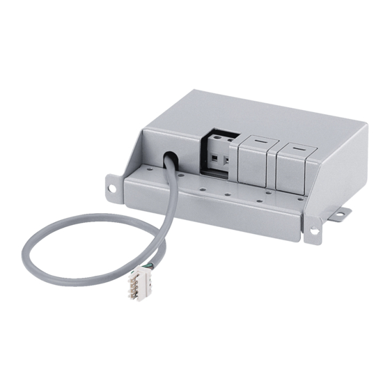
Miele DSM 400 Funktionsbeschreibung/Montageanweisung
Für dunstabzugshaube da 6000 w
Vorschau ausblenden
Andere Handbücher für DSM 400:
- Gebrauchs- und montageanweisung (48 Seiten) ,
- Montageanweisung (40 Seiten) ,
- Funktionsbeschreibung/montageanweisung (24 Seiten)
Inhaltszusammenfassung für Miele DSM 400
- Seite 1 Funktionsbeschreibung/ Montageanweisung Steuermodul DSM 400 für Dunstabzugshaube DA 6000 W Operation/Installation Control module DSM 400 for Cooker Hood DA 6000 W de, en M.-Nr. 09 165 660...
-
Seite 2: Inhaltsverzeichnis
Inhalt/Contents de - Funktionsbeschreibung ......... 3 de –... -
Seite 3: De - Funktionsbeschreibung
de - Funktionsbeschreibung Das Steuermodul bietet folgende Mög- lichkeiten: 1. Anschluss eines Lichttasters Darüber hinaus bietet das Steuermodul die Möglichkeit, über einen in die Haus- installation integrierten Lichttaster die Beleuchtung der Dunstabzugshaube zu schalten. 2. Potentialfreier Anschluss Er dient zum Steuern eines anderen Gerätes in Abhängigkeit vom Schaltzu- stand des Gebläses der Dunstabzugs- haube. -
Seite 4: De - Elektrischer Anschluss
de – Elektrischer Anschluss ^ Zum Anschließen ist der Deckel des Zusatzlichttaster Steuermoduls abzunehmen und (Anschluss nur durch eine Elek- nachher wieder zu montieren. tro-Fachkraft) ^ Der Anschluss a muss gebrückt werden. ^ Am mittleren Anschluss b des Steu- ermoduls lässt sich ein in der Ge- bäudeinstallation integrierter Lichttas- ter anschließen. -
Seite 5: Potentialfreier Kontakt
de – Elektrischer Anschluss Der Anschluss c des Steuermoduls Potentialfreier Kontakt. bietet einen potentialfreien Kontakt. Er (Anschluss nur durch eine Elek- kann z.B. dazu genutzt werden, andere tro-Fachkraft) Geräte in Abhängigkeit vom Schaltzu- stand des Gebläses der Dunstabzugs- haube zu steuern. Der Kontakt c liefert keine definierte Spannung (potentialfrei). -
Seite 6: En - Installation - Operation
en – Installation - Operation The control module enables the following: 1. Connection to a light switch The control module can also be used to switch the cooker hood lighting on via a light switch in the house. 2. Potential free connection This enables another appliance to be controlled according to the switch setting on the cooker hood fan. -
Seite 7: En - Electrical Connection
en – Electrical connection ^ Before connecting to an additional Additonal light switch light switch the lid of the control (connection must be made a suitably module has to be taken off. It is qualified electrician only) refitted later. ^ Terminal a must be bridged. ^ Connection can be made to a light switch in the home via the middle terminal b in the control module. -
Seite 8: Potential Free Contact
en – Electrical connection Potential free contact. Potential free contact can be accessed using terminal c on the control module. (connection must be made a suitably This enables another appliance to be qualified electrician only) controlled according to the switch setting on the cooker hood fan. -
Seite 10: En - Installation
de - Montage en - Installation de – Diese Montageanweisung beschreibt die Arbeitsschritte bei Erstmontage der Dunstabzugshaube. Beachten Sie dazu die Gebrauchsanweisung und den Montageplan der DA 6000 W. Soll das Steuermodul in die bereits installierte Dunstabzugshaube montiert werden, ist dies nur durch den Kundendienst möglich. - Seite 11 de - Montage en - Installation...
- Seite 12 de - Montage en - Installation...
- Seite 13 de - Montage en - Installation...
- Seite 14 de - Montage en - Installation...
-
Seite 15: En - Wiring Diagram
de – Schaltplan en – Wiring diagram... - Seite 16 Änderungen vorbehalten / 2011 M.-Nr. 09 165 660 / 00...


