Anmelden
Hochladen
Anleitungen
Marken
HP Anleitungen
Drucker
LaserJet Enterprise 700 M712dn
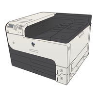
HP LaserJet Enterprise 700 M712dn Handbücher
Anleitungen und Benutzerhandbücher für HP LaserJet Enterprise 700 M712dn. Wir haben
1
HP LaserJet Enterprise 700 M712dn Anleitung zum kostenlosen PDF-Download zur Verfügung: Handbuch Zur Fehlerbehebung
HP LaserJet Enterprise 700 M712dn Handbuch Zur Fehlerbehebung (366 Seiten)
Marke:
HP
| Kategorie:
Drucker
| Dateigröße: 14.64 MB
Inhaltsverzeichnis
Table of Contents
7
Conventions Used in this Guide
5
Inhaltsverzeichnis
7
List of Figures
23
Theory of Operation
27
Basic Operation
28
Figure 1-1 Function Structure
28
Function Structure
28
Operation Sequence
28
Table 1-1 Operation Sequence
29
Engine Control System
30
Figure 1-2 Engine Control System
30
DC Controller PCA
31
Figure 1-3 DC Controller PCA
31
Motor Control
32
Failure Detection
33
Figure 1-4 Motor Locations
33
Motor Locations
33
Table 1-2 Motor Locations
33
Fan Control
34
Failure Detection
35
Fan Locations
35
Figure 1-5 Fan Locations
35
Table 1-3 Fan Locations
35
Figure 1-6 Low-Voltage Power-Supply PCA
36
Low-Voltage Power-Supply PCA
36
Over-Current/Over-Voltage/Overload Protection
37
Power Supply Voltage Detection
37
Safety Interruption
37
Table 1-4 Low Voltage Power Supply DC Power Specifications
37
Power Supply Illumination Control
38
Sleep Mode
38
Figure 1-7 High-Voltage Power-Supply PCA
39
High-Voltage Power-Supply PCA
39
Figure 1-8 Fuser Components
41
Fuser Control
41
Figure 1-9 Fuser Control System
42
Fuser Heater Protective Function
43
Fuser Temperature Control
43
Fuser Failure Detection
44
Pressure Roller Cleaning
45
Laser Scanner System
46
Figure 1-10 Laser Scanner System
46
Laser Scanner Failure Detection
47
Laser Scanner Safety Function
47
Image-Formation System
48
Figure 1-11 Image-Formation System
48
Figure 1-12 Image-Formation Components
49
Image-Formation Process
49
Figure 1-13 Image-Formation Process
50
Figure 1-14 Primary Charging
50
Latent-Image Formation Block
50
Step 1: Primary Charging
50
Development Block
51
Figure 1-15 Laser-Beam Exposure
51
Figure 1-16 Developing
51
Step 2: Laser-Beam Exposure
51
Step 3: Developing
51
Figure 1-17 Image Transfer
52
Figure 1-18 Separation from the Drum
52
Step 4: Image Transfer
52
Step 5: Separation from the Drum
52
Transfer Block
52
Drum-Cleaning Block
53
Fuser Block
53
Step 6: Fusing
53
Step 7: Drum Cleaning
53
Toner Cartridge
53
Figure 1-19 Fusing
53
Figure 1-20 Drum Cleaning
53
Figure 1-21 Toner Cartridge Components
54
Other Image-Formation Functions
55
Drum Discharge
55
Figure 1-22 Drum Discharge
55
Transfer Roller Cleaning
55
Environment Change Control
56
Figure 1-23 Transfer Roller Cleaning
56
Pickup, Feed, and Delivery System
57
Figure 1-24 Pickup, Feed, and Delivery System
57
Table 1-5 Pickup, Feed, and Delivery System Sensors and Switches
58
Figure 1-25 Pickup, Feed, and Delivery System Sensors and Switches
58
Table 1-6 Pickup, Feed, and Delivery System Solenoid and Motors
59
Figure 1-26 Pickup, Feed, and Delivery-System Solenoid and Motors
59
Figure 1-27 Pickup and Feed Block
60
Pickup and Feed Block
60
Cassette Media-Size Detection and Cassette-Presence Detection
61
Cassette Pickup
61
Figure 1-28 Cassette Pickup Mechanism
61
Cassette Lift Operation
62
Lift-Down Operation
62
Lift-Up Operation
62
Table 1-7 Media Switch Combinations
62
Cassette Media-Presence Detection
63
Cassette Multiple-Feed Prevention
63
Figure 1-29 Cassette Lift Operation
63
Figure 1-30 Cassette Multiple Feed Prevention
64
Figure 1-31 MP Tray Pickup
65
MP Tray Media-Presence Detection
65
MP Tray Pickup
65
Feed-Speed Control
66
Figure 1-32 MP Tray Multiple-Feed Prevention
66
MP Tray Multiple-Feed Prevention
66
Figure 1-33 Skew-Feed Prevention
68
Skew-Feed Prevention
68
Media-Length Detection
69
Figure 1-34 Fuse and Delivery Block
70
Fuse and Delivery Block
70
Loop Control
70
Figure 1-35 Loop Control
71
Figure 1-36 Output bin Media-Full Detection
72
Output bin Media-Full Detection
72
Figure 1-37 Product Engine Jam Detection Sensors and Switches
73
Jam Detection
73
No Pick Jam 1
73
Feed Stay Jam 1
74
Fuser Output Delay Jam 1
74
Fuser Output Stay Jam 1
74
Output Delay Jam 1
74
Output Delay Jam 2
74
Output Stay Jam 1
74
Automatic Delivery
75
Door Open Jam 1
75
Fuser Wrap Jam 1
75
Multiple-Feed Jam 1
75
Residual Paper Jam 1
75
500-Sheet Paper Feeder (Tray 4)
76
Figure 1-38 500-Sheet Paper Feeder Paper Path
76
Figure 1-39 500-Sheet Paper Feeder Signal Flow
76
500-Sheet Paper Feeder Failure Detection
77
500-Sheet Paper Feeder Motor Control
77
Figure 1-40 500-Sheet Paper Feeder Motor Locations
77
Table 1-8 500-Sheet Paper Feeder Electrical Components
77
Table 1-9 500-Sheet Paper Feeder Motors
77
500-Sheet Paper Feeder Pickup and Feed Operation
78
Figure 1-41 500-Sheet Paper Feeder Pickup and Feed Components
78
Table 1-10 500-Sheet Paper Feeder Pickup and Feed Components
78
500-Sheet Paper Feeder Cassette Media-Size Detection and Cassette-Presence Detection
79
500-Sheet Paper Feeder Cassette Pickup
79
Figure 1-42 500-Sheet Paper Feeder Pickup and Feed Cassette Pickup
79
500-Sheet Paper Feeder Lift-Up Operation
80
Figure 1-43 500-Sheet Paper Feeder Lift-Up Operation
80
Table 1-11 500-Sheet Paper Feeder Media Switch Combinations
80
500-Sheet Paper Feeder Cassette Media-Presence Detection
81
500-Sheet Paper Feeder Cassette Multiple-Feed Prevention
81
500-Sheet Paper Feeder Jam Detection
82
Figure 1-44 500-Sheet Paper Feeder Multiple-Feed Prevention
82
Figure 1-45 500-Sheet Paper Feeder Cassette Jam Detection Sensor
82
No Pick Jam 2
82
Residual Paper Jam 1
82
500-Sheet Paper Feeder Automatic Delivery
83
Door Open Jam 1
83
1X500 and 3X500 Paper Feeder and Stand
84
Figure 1-46 Paper Deck Paper Path
84
Figure 1-47 Paper Deck Signal Flow
85
Table 1-12 Paper Deck Electrical Components
85
Figure 1-48 Paper Deck Motors
87
Paper Deck Failure Detection
87
Paper Deck Motor Control
87
Paper Deck Pickup-And-Feed Operation
87
Table 1-13 Paper Deck Motors
87
Figure 1-49 Paper Deck Pickup and Feed Components
88
Table 1-14 Paper Deck Pickup-And-Feed Operation Components
88
Paper Deck Cassette Media-Size Detection and Cassette-Presence Detection
89
Table 1-15 Paper Deck Media Switch Combinations
89
Figure 1-50 Paper Deck Lift-Up Operation
90
Paper Deck Lift-Up Operation
90
Figure 1-51 Paper Deck Jam Detection Sensors
91
No Pick Jam 2
91
Paper Deck Cassette Media-Presence Detection
91
Paper Deck Jam Detection
91
Door Open Jam 1
92
No Pick Jam 3 (3X500-Sheet Paper Deck Only)
92
Paper Deck Automatic Delivery
92
Residual Paper Jam 1
92
3,500-Sheet High-Capacity Input (HCI) Feeder
93
Figure 1-52 HCI Paper Path
93
Figure 1-53 HCI Signal Flow
94
Table 1-16 HCI Electrical Components
94
Figure 1-54 HCI Motors
95
HCI Failure Detection
95
HCI Motor Control
95
Table 1-17 HCI Motors
95
Figure 1-55 HCI Pickup-And-Feed Operation
96
HCI Pickup-And-Feed Operation
96
Table 1-18 HCI Pickup-And-Feed Operation Components
96
HCI Cassette Media-Size Detection and Cassette-Presence Detection
97
Figure 1-56 HCI Lift-Up Operation
98
HCI Cassette Media-Presence Detection
98
HCI Lift-Up Operation
98
Figure 1-57 HCI Jam Detection Sensors
100
HCI Jam Detection
100
No Pick Jam 2
100
No Pick Jam 3
100
Door Open Jam 1
101
HCI Automatic Delivery
101
Residual Paper Jam 1
101
Duplexer
102
Figure 1-58 Duplexer Paper Path
102
Figure 1-59 Duplexer Signal Flow
102
Duplexer Motor Control
103
Duplexer Motor Failure Detection
103
Figure 1-60 Duplexer Motor
103
Table 1-19 Duplexer Electrical Components
103
Table 1-20 Duplexer Motor
103
Duplexer Fan Control
104
Duplexer Fan Failure Detection
104
Duplexer Reverse and Feed Operation
104
Figure 1-61 Duplexer Fan
104
Table 1-21 Duplexer Fan
104
Duplexer Reverse and Feed Operation Sequence
105
Figure 1-62 Duplexer Reverse and Feed Operation
105
Table 1-22 Duplexer Reverse and Feed Components
105
Side Misregistration Detection
106
Figure 1-63 Duplexer Side Misregistration Detection
107
Duplexer Jam Detection
108
Figure 1-64 Duplexer Jam Detection Sensors
108
Fuser Output Stay Jam 2
108
Side Misregistration Failure Detection
108
Duplex Re-Pickup Jam 1
109
Duplex Re-Pickup Jam 2
109
Duplex Re-Pickup Jam 3
109
Duplexer Automatic Delivery
109
Residual Paper Jam 1
109
Reverse Jam 1
109
Solve Problems
111
Solve Problems Checklist
112
Menu Map
114
Preboot Menu Options
115
Table 2-1 Preboot Menu Options (1 of 6)
116
Table 2-2 Preboot Menu Options (2 of 6)
118
Table 2-3 Preboot Menu Options (3 of 6)
119
Table 2-4 Preboot Menu Options (4 of 6)
120
Table 2-5 Preboot Menu Options (5 of 6)
121
Table 2-6 Preboot Menu Options (6 of 6)
121
Current Settings Pages
123
Troubleshooting Process
124
Determine the Problem Source
124
Table 2-7 Troubleshooting Flowchart
124
Troubleshooting Flowchart
124
Power Subsystem
125
Power-On Checks
125
Power-On Troubleshooting Overview
125
Tools for Troubleshooting
127
Individual Component Diagnostics
127
LED Diagnostics
127
Understand Lights on the Formatter
127
Table 2-8 Heartbeat LED, Product Initialization
128
Engine Diagnostics
130
Engine-Test Button
130
HP Jetdirect Leds
130
Figure 2-1 Locating the Engine-Test-Page Switch
131
Paper Path Sensor Tests
132
Paper Path Test
132
Table 2-9 Paper-Path Sensors
133
Manual Sensor Tests
134
Table 2-10 Manual Sensor Tests
134
Cartridge Door Switch (SW3)
136
Figure 2-2 Test the Cartridge Door Switch
136
Figure 2-3 Test the Left Door Switch
137
Left Door Switch (SW1)
137
Right Door Sensor (SR8)
138
Cartridge Install Sensor (SR1)
139
Figure 2-4 Test the Top Sensor
140
Top (Top-Of-Page) Sensor (SR9)
140
Figure 2-5 Fuser Loop Sensor
141
Fuser Loop Sensor (SR6)
141
Figure 2-6 Fuser Output Sensor
142
Fuser Output Sensor (SR12)
142
Duplex Switchback Sensor (SR1)
143
Figure 2-7 Duplex Switchback Sensor
143
Duplexer Refeed Sensor (SR2)
144
Figure 2-8 Duplexer Refeed Sensor
144
Figure 2-9 Tray 4 Feed Sensor
145
Tray 4 Feed Sensor (SR1)
145
Figure 2-10 Output Sensor
146
Output Sensor (SR3)
146
Table 2-11 Tray/Bin Manual Sensor Test
147
Tray/Bin Manual Sensor Tests
147
Figure 2-11 Tray 1 Paper Sensor
149
Main Product Trays
149
Figure 2-12 Tray 2 Paper Sensor
150
Figure 2-13 Tray 2 Paper Surface Sensor
151
Figure 2-14 Tray 2 Paper Size Switches
152
Figure 2-15 Tray 3 Paper Sensor
153
Figure 2-16 Tray 3 Paper Surface Sensor
154
Figure 2-17 Tray 3 Paper Size Switches
155
Figure 2-18 Output bin Full Sensor
156
Figure 2-19 Tray 4 Paper Sensor
157
Optional 500-Sheet Paper Tray (Tray 4)
157
Figure 2-20 Tray 4 Paper Surface Sensor
158
Figure 2-21 Tray 4 Paper Size Switches
159
Figure 2-22 Tray 4 Feed Sensor
160
Figure 2-23 Lower Right Door Sensor
161
1X500 and 3X500 Paper Deck Trays
162
Figure 2-24 Test the Tray 4 Door Switch
162
Figure 2-25 Tray 4 Paper Sensor
164
HCI Trays
164
Figure 2-26 Tray 4 Paper Surface Sensor
165
Figure 2-27 Tray 4 Paper Size Sensor
165
Figure 2-28 Tray 4 Paper Feed Sensor
166
Figure 2-29 Tray 4 Door Open Sensor
167
Figure 2-30 Tray 5 Paper Sensor
167
Figure 2-31 Tray Paper Surface Sensor
168
Figure 2-32 Tray 5 Paper Size Sensor
169
Figure 2-33 Tray 5 Feed Sensor
169
Figure 2-34 HCI Exit Sensor
170
Print/Stop Test
170
Component Tests
171
Control-Panel Tests
171
Half Self-Test
171
Component Test (Special-Mode Test)
172
Drum Rotation Test Check
172
Table 2-12 Component Tests
172
Block Diagrams
174
Diagrams
174
Figure 2-35 Product Cross Section
174
Table 2-13 Product Cross Section
174
Figure 2-36 Optional Paper Feeder (Tray 4) Cross Section
175
Table 2-14 Optional Paper Feeder (Tray 4) Cross Section
175
Figure 2-37 1X500-Sheet Paper Deck Cross Section
176
Table 2-15 1X500-Sheet Paper Deck Cross Section
176
Figure 2-38 3X500-Sheet Paper Deck Cross Section
177
Table 2-16 3X500-Sheet Paper Deck Cross Section
177
Figure 2-39 3,500-Sheet HCI Cross Section
178
Table 2-17 3,500-Sheet HCI Cross Section
178
DC Controller Connections
179
Figure 2-40 DC Controller Connections
179
Location of Connectors
179
Table 2-18 DC Controller Connections
179
Plug/Jack Locations
181
Table 2-19 Plug/Jack Locations
181
Figure 2-41 External Component Locations
182
Locations of Major Components
182
Table 2-20 External Component Locations
182
Figure 2-42 Major Component Locations (1 of 3)
183
Table 2-21 Major Component Locations (1 of 3)
183
Figure 2-43 Major Component Locations (2 of 3)
184
Figure 2-44 Major Component Locations (3 of 3)
184
Table 2-22 Major Component Locations (2 of 3)
184
Table 2-23 Major Component Locations (3 of 3)
184
Figure 2-45 PCA Locations
185
Table 2-24 PCA Locations
185
Figure 2-46 Motor Locations
186
Figure 2-47 Fan Locations
186
Table 2-25 Motor Locations
186
Table 2-26 Fan Locations
186
Figure 2-48 Roller Locations
187
Table 2-27 Roller Locations
187
Figure 2-49 500-Sheet Feeder External Component Locations
188
Table 2-28 500-Sheet Feeder External Component Locations
188
Figure 2-50 500-Sheet Feeder Internal Component Locations
189
Table 2-29 500-Sheet Feeder Internal Component Locations
189
Figure 2-51 1X500 Paper Deck External Component Locations
190
Table 2-30 1X500 Paper Deck External Component Locations
190
Figure 2-52 1X500 Paper Deck Internal Component Locations
191
Table 2-31 1X500 Paper Deck Internal Component Locations
191
Figure 2-53 3X500 Paper Deck External Component Locations
192
Table 2-32 3X500 Paper Deck External Component Locations
192
Figure 2-54 3X500 Paper Deck Internal Component Locations
193
Table 2-33 3X500 Paper Deck Internal Component Locations
193
Figure 2-55 HCI External Component Locations
194
Table 2-34 HCI External Component Locations
194
Figure 2-56 HCI Internal Component Locations (1 of 2)
195
Table 2-35 HCI Internal Component Locations (1 of 2)
195
Figure 2-57 HCI Internal Component Locations (2 of 2)
196
Table 2-36 HCI Internal Component Locations (2 of 2)
196
Figure 2-58 General Timing Chart
197
General Timing Charts
197
Circuit Diagrams
198
Figure 2-59 General Circuit Diagram (1 of 2)
198
Figure 2-60 General Circuit Diagram (2 of 2)
199
Clean the Paper Path
200
Internal Test Pages
200
Set up an Auto Cleaning Page
200
Configuration Page
201
Figure 2-61 Configuration Page
201
Print a Configuration Page
201
Figure 2-62 HP Embedded Jetdirect Page
202
HP Embedded Jetdirect Page
202
Finding Important Information on the Configuration Pages
203
Table 2-37 Important Information on the Configuration
203
Administration Menu
204
Control Panel Menus
204
Reports Menu
204
General Settings Menu
205
Table 2-38 Reports Menu
204
Device Maintenance Menu
236
Backup/Restore Menu
236
Calibration/Cleaning Menu
237
Table 2-39 General Settings Menu
205
General Print Settings Menu
211
Table 2-40 General Print Settings Menu
212
Default Print Options Menu
214
Table 2-41 Default Print Options Menu
214
Display Settings Menu
215
Table 2-42 Display Settings Menu
216
Manage Supplies Menu
217
Table 2-43 Manage Supplies Menu
217
Manage Trays Menu
218
Network Settings Menu
220
Table 2-44 Manage Trays Menu
220
Table 2-46 Jetdirect Menu
221
Troubleshooting Menu
234
Table 2-45 Network Settings Menu
221
Table 2-47 Troubleshooting Menu
234
Table 2-48 Backup/Restore Menu
237
Table 2-49 Calibration/Cleaning Menu
237
Service Menu
238
USB Firmware Upgrade Menu
238
Interpret Control-Panel Messages
239
20.00.00 Insufficient Memory: to Continue, Touch "OK
239
Control-Panel Message Types
239
Control-Panel Messages
239
YY Internal Clock Error to Continue, Touch "OK
239
21.00.00 Page too Complex to Continue, Touch "OK
240
33.WX.YZ Used Board/Disk Installed
240
40.00.01 USB I/O Buffer Overflow to Continue, Touch "OK
240
40.00.02 Embedded I/O Buffer Overflow to Continue, Touch "OK
240
40.00.03 EIO Buffer Overflow to Continue, Touch "OK
240
40.00.04 EIO Bad Transmission to Continue, Touch "OK
241
40.00.05 Embedded I/O Bad Transmission to Continue, Touch "OK
241
41.03.YZ Unexpected Size in Tray
241
41.05.YZ Unexpected Type in Tray
242
Options
242
41.05.YZ Unexpected Type in Tray to Use Another Tray, Touch "Options
243
WX.YZ Error to Use Another Tray, Touch "Options
244
47.FC.YZ Printer Calibration Failed to Continue, Touch "OK
246
47.WX.YZ Printer Calibration Failed
247
49.XX.YY Error to Continue Turn off then on
247
50.WX.YZ Fuser Error to Continue Turn off then on
247
51.00.YY Error to Continue Turn off then on
251
52.00.00 Error to Continue Turn off then on
251
Error to Continue Turn off then on
252
54.XX.YY Error
252
55.XX.YY DC Controller Error to Continue Turn off then on
253
56.00.YY Error to Continue Turn off then on
253
57.00.0X Error
254
58.00.04 Error to Continue Turn off then on
254
59.00.20 Error to Continue Turn off then on
255
59.05.60 Error to Continue Turn off then on
256
60.00.0Y Tray Lifting Error
256
62.00.00 no System to Continue Turn off then on
256
69.11.YY Error to Continue, Touch "OK
257
70.00.00 Error to Continue Turn off then on
257
81.WX.YZ Embedded Jetdirect Error to Continue Turn off then on
257
81.YY.YY EIO Error to Continue Turn off then on
258
98.00.0X Corrupt Data in X Volume
258
Full Remove All Paper from bin
258
Bad Optional Tray Connection
259
Black Cartridge Low
259
Black Cartridge very Low
259
Black Cartridge very Low to Continue, Touch "OK
259
Card Slot Device Failure to Clear Touch "Clear
260
Card Slot File Operation Failed to Clear Touch "Clear
260
Card Slot File System Is Full to Clear Touch "Clear
260
Card Slot Is Write Protected to Clear Touch "Clear
260
Card Slot Not Initialized to Clear Touch "Clear
260
Cartridge Ship Mode
261
Chosen Personality Not Available to Continue, Touch "OK
261
Cleaning Disk % Complete Do Not Power off
261
Close Left Door
261
Close Top Cover
262
Data Received
262
Disk Full Delete Stored Jobs
262
Disk Low Delete Stored Jobs
262
EIO Device Failure to Clear Touch "Clear
263
EIO Disk Not Functional
263
EIO Disk Spinning up
263
EIO File Operation Failed to Clear Touch "Clear
263
EIO File System Is Full to Clear Touch "Clear
263
EIO Is Write Protected to Clear Touch "Clear
264
EIO Not Initialized to Clear Touch "Clear
264
Event Log Is Empty
264
Fuser Kit Low
264
Fuser Kit very Low
264
Fuser Kit very Low to Continue, Touch "OK
265
Incompatible
265
Incompatible Supplies
265
Initializing
266
Install Black Cartridge
266
Install Fuser Unit
266
Install Supplies
266
Internal Disk Device Failure to Clear Touch "Clear
266
Internal Disk File Operation Failed to Clear Touch "Clear
267
Internal Disk File System Is Full to Clear Touch "Clear
267
Internal Disk Is Write Protected to Clear Touch "Clear
267
Internal Disk Not Found
267
Internal Disk Not Functional
267
Internal Disk Not Initialized to Clear Touch "Clear
268
Internal Disk Spinning up
268
Load Tray 1 [Type] [Size]
268
Load Tray 1 [Type] [Size] to Continue, Touch "OK
268
Load Tray : [Size]
268
Load Tray : [Size] to Continue, Touch "OK
269
Load Tray : [Size] to Use Another Tray, Touch "Options
269
Load Tray : [Type], [Size]
269
Load Tray : [Type], [Size] to Use Another Tray, Touch "Options
270
Manually Feed Output Stack then Touch "OK" to Print Second Sides
270
Manually Feed: [Size]
271
Manually Feed: [Size] to Continue, Touch "OK
271
Manually Feed: [Size] to Use Another Tray, Touch "Options
271
Manually Feed: [Type], [Size] to Continue, Touch "OK
272
Manually Feed: [Type], [Size] to Use Another Tray, Touch "Options
272
No Job to Cancel
272
Output bin Full
272
Paperless Mode
273
Printing Engine Test
273
Printing Stopped to Continue, Touch "OK
273
RAM Disk Device Failure to Clear Touch "Clear
273
RAM Disk File Operation Failed to Clear Touch "Clear
273
RAM Disk File System Is Full to Clear Touch "Clear
274
RAM Disk Is Write Protected to Clear Touch "Clear
274
RAM Disk Not Initialized to Clear Touch "Clear
274
Remove Cartridge Lock
274
Remove the Toner Cartridge
274
Replace Black Cartridge
275
Replace Fuser Kit
275
Replace Supplies
275
ROM Disk Device Failed to Clear Touch "Clear
276
ROM Disk File Operation Failed to Clear Touch "Clear
276
ROM Disk File System Is Full to Clear Touch "Clear
276
ROM Disk Is Write Protected to Clear Touch "Clear
276
ROM Disk Not Initialized to Clear Touch "Clear
276
Size Mismatch in Tray
277
Standard bin Full Remove All Paper from bin
277
Supplies Low
277
Supplies very Low to Continue, Touch "OK
277
Supply Memory Warning
278
Tray Empty: [Size]
278
Tray Empty: [Type], [Size]
278
Tray Open
278
Tray Overfilled Remove Excess Paper
279
Tray Overfilled to Use Another Tray, Touch "Options
279
Type Mismatch Tray
279
Unable to Cancel Firmware Update Job
280
Unable to Install the Firmware
280
Unsupported Drive Installed
280
Unsupported Supply in Use
280
Unsupported Supply Installed
281
Unsupported Supply Installed to Continue, Touch "OK
281
Unsupported Tray Configuration
281
Unsupported USB Accessory Detected Remove USB Accessory
281
Then on
282
Upgrade Complete to Continue Turn off then on
282
USB Accessory Not Functional
282
USB Hubs Are Not Fully Supported some Operations May Not Work Properly
282
USB Is Write Protected to Clear Touch "Clear
282
USB Not Initialized to Clear Touch "Clear
283
USB Storage Accessory Removed Clearing any Associated Data
283
USB Storage Device Failure to Clear Touch "Clear
283
USB Storage File Operation Failed to Clear Touch "Clear
283
USB Storage File System Is Full to Clear Touch "Clear
283
Used Supply in Use
283
Used Supply Installed to Continue, Touch "OK
284
Event Log Messages
285
Figure 2-63 Sample Event Log
285
Clear an Event Log
286
Event Log Message Table
286
Print or View an Event Log
286
Clear Jams
289
Auto-Navigation for Clearing Jams
289
Jam Locations
289
Clear Jams in the Output-Bin Area
290
Clear Jams in Tray 1
290
Clear Jams in Tray 2 or Tray 3
291
Clear Jams in the 500-Sheet Trays
293
Clear Jams in the 3,500-Sheet High-Capacity Tray
294
Clear Jams from the Toner-Cartridge Area
297
Clear Jams in the Fuser
300
Clear Jams from the Duplexer
302
Solve Paper-Handling Problems
303
The Product Does Not Pick up Paper
303
The Product Picks up Multiple Sheets of Paper
303
Table 2-50 Print Modes under the Adjust Paper Types Sub Menu
304
Use Manual Print Modes
304
Print Quality
304
Table 2-51 MP Modes under the Optimize Submenu
305
Print Quality Troubleshooting Tools
306
Repetitive Defects Measurements
306
Solve Image-Quality Problems
307
Image Defect Examples
307
Clean the Product
315
Print a Cleaning Page
315
Solve Performance Problems
316
Solve Connectivity Problems
317
Solve USB Connection Problems
317
Solve Wired Network Problems
317
The Computer Is Using the Incorrect IP Address for the Product
317
The Product Has a Poor Physical Connection
317
New Software Programs Might be Causing Compatibility Problems
318
The Computer Is Unable to Communicate with the Product
318
The Computer or Workstation Might be Set up Incorrectly
318
The Product Is Disabled, or Other Network Settings Are Incorrect
318
The Product Is Using Incorrect Link and Duplex Settings for the Network
318
Service Menu
319
Service Mode Functions
319
Product Resets
320
Restore Factory-Set Defaults
320
Restore the Service ID
320
Convert the Service ID to an Actual Date
321
Product Cold Reset
321
Active and Repository Firmware Locations
322
Format Disk and Partial Clean Functions
322
Partial Clean
322
Execute a 3 Partial Clean
323
Format Disk
323
Execute a 2 Format Disk
324
Determine the Installed Revision of Firmware
325
Embedded Web Server
325
Perform a Firmware Upgrade
325
Product Firmware Upgrades
325
USB Storage Device (Preboot Menu)
326
USB Storage Device (Control-Panel Menu)
328
Appendix A Service and Support
330
Hewlett-Packard Limited Warranty Statement
330
Hp's Premium Protection Warranty: Laserjet Toner Cartridge Limited Warranty Statement
332
HP Policy on Non-HP Supplies
333
HP Anticounterfeit Web Site
334
Data Stored on the Toner Cartridge
335
End User License Agreement
336
Openssl
339
Customer Self-Repair Warranty Service
340
Customer Support
341
Appendix B Product Specifications
343
Physical Specifications
344
Power Consumption, Electrical Specifications, and Acoustic Emissions
344
Environmental Specifications
344
Appendix C Regulatory Information
345
FCC Regulations
346
Environmental Product Stewardship Program
347
Ozone Production
347
Paper Use
347
Plastics
347
Power Consumption
347
Protecting the Environment
347
Toner Consumption
347
HP Laserjet Print Supplies
348
Multiple Returns (more than One Cartridge)
348
Return and Recycling Instructions
348
Shipping
348
Single Returns
348
United States and Puerto Rico
348
Material Restrictions
349
Non-U.S. Returns
349
Paper
349
Chemical Substances
350
Disposal of Waste Equipment by Users
350
Electronic Hardware Recycling
350
For more Information
350
Material Safety Data Sheet (MSDS)
350
Declaration of Conformity
352
Safety Statements
354
Canadian DOC Regulations
354
Laser Safety
354
Power Cord Instructions
354
Power Cord Statement (Japan)
354
VCCI Statement (Japan)
354
EMC Statement (China)
355
EMC Statement (Korea)
355
EMI Statement (Taiwan)
355
Laser Statement for Finland
355
GS Statement (Germany)
357
Restriction on Hazardous Substances Statement (Turkey)
357
Restriction on Hazardous Substances Statement (Ukraine)
357
Substances Table (China)
357
Index
359
Werbung
Werbung
Verwandte Produkte
HP LASERJET ENTERPRISE 700 M712
HP LaserJet Enterprise 700 M712n
HP LaserJet Enterprise 700 M712xh
HP LaserJet Enterprise 700
HP OFFICEJET 7000
HP Latex 700W
HP Photosmart 7350
HP Photosmart 7400 Series
HP Photosmart 7400 Serie
HP Smart Tank 7300-Serie
HP Kategorien
Drucker
All-in-One-Drucker
Notebooks
PCs
Server
Weitere HP Anleitungen
Anmelden
Anmelden
ODER
Mit Facebook anmelden
Mit Google anmelden
Anleitung hochladen
Von PC hochladen
Von URL hochladen