Inhaltsverzeichnis
Werbung
Quicklinks
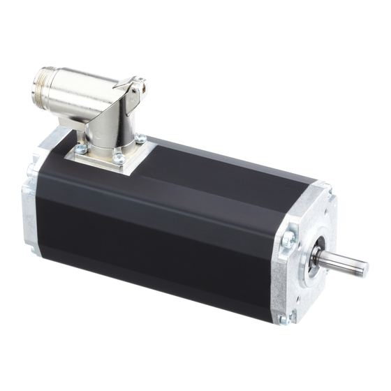
BG 45 SI
Instruction Manual
BLDC motor with parametrizable
motion controller integrated
Betriebsanleitung
Bürstenloser DC - Motor mit integriertem
parametrierbarem Drehzahlregler
Dunkermotoren GmbH
Allmendstraße 11 · D-79848 Bonndorf/Schwarzwald
www.dunkermotoren.com · info@dunkermotoren.de
Phone +49 (0) 7703 930-0 · Fax +49 (0) 7703 930-210/212
Motor
Part No.
45x15
88545.070XX
45x30
88545.080XX
Werbung
Inhaltsverzeichnis

Verwandte Anleitungen für Ametek dunkermotoren BG 45 SI Serie


Inhaltszusammenfassung für Ametek dunkermotoren BG 45 SI Serie
- Seite 1 BG 45 SI Motor Part No. 45x15 88545.070XX 45x30 88545.080XX Instruction Manual BLDC motor with parametrizable motion controller integrated Betriebsanleitung Bürstenloser DC - Motor mit integriertem parametrierbarem Drehzahlregler Dunkermotoren GmbH Allmendstraße 11 · D-79848 Bonndorf/Schwarzwald www.dunkermotoren.com · info@dunkermotoren.de Phone +49 (0) 7703 930-0 · Fax +49 (0) 7703 930-210/212...
-
Seite 2: Inhaltsverzeichnis
1 Content 1 Inhalt 2 About this document 2 Über dieses Dokument 3 General description 3 Allgemeine Beschreibung 3.1 Motor series BG 45 SI 3.1 Motorbaureihe BG 45 SI 3.2 Explanations of terms used 3.2 Begriffserklärungen 3.3 Proper use 3.3 Bestimmungsgemäße Verwendung 3.4 Standards and guidelines 3.4 Zertifikate/ Konformitäten 4 Safety instructions... - Seite 3 7.3.3 7.3.3 Schematic circuit of the digital inputs Prinzipschaltung der Digitaleingänge 7.4 Analog inputs 7.4 Analoge Eingänge 7.4.1 Function analog input 7.4.1 Funktion analoger Eingang 7.4.2 7.4.2 Prinzipschaltung Analogeingang Schematic circuit of the analog input 7.5 Digital outputs 7.5 Digitale Ausgänge 7.5.1 Function digital outputs 7.5.1 Funktion digitale Ausgänge 7.5.2...
-
Seite 4: About This Document
2 About this document 2 Über dieses Dokument These operating instructions introduce you to the SI Die vorliegende Betriebsanleitung stellt Ihnen die SI- drives and provide you with information on all the Antriebe vor und informiert Sie über alle Schritte zur stages required for the installation of the drives and Installation der Antriebe und zur Durchführung von the performance of functional tests. -
Seite 5: General Description
3 Allgemeine Beschreibung 3 General description 3.1 Motorbaureihe BG 45 SI 3.1 Motor series BG 45 SI • Bürstenloser DC - Antrieb mit integrierter • Brushless DC - motor with an integrated speed Drehzahlregelelektronik für 4-Quadrantenbetrieb. control electronics for 4-quadrant operation. •... -
Seite 6: Explanations Of Terms Used
3.2 Explanations of terms used 3.2 Begriffserklärungen Term Explanation Begriff Erklärung Bauteil zur Glättung von Component to smooth the Smoothing capacitor Glättungskondensator Spannungsschwan- fluctuation voltage kungen Sensors for determining Sensor zur Positionsbe- Hall sensors Hallsensoren the position of a rotor stimmung des Rotors Einstellungen zum Be- Settings to accelerate and... -
Seite 7: Safety Instructions
4 Safety instructions Grundlegende Sicherheitshinweise Before commissioning, it is Vor der Inbetriebnahme sind unbe- essential that the safety instructions dingt die Sicherheitshinweise zu lesen in the relevant section are read and und zu beachten! Eine Nichtbeach- understood, and then observed! tung kann zu Gefahren bei Personen Non-observance can result in danger oder Beschädigungen an der... -
Seite 8: Technical Data, Accessories
5 Technical data, accessories 5 Technische Daten, Zubehör 5.1 Electrical data 5.1 Elektrische Daten 0 ... 33 VDC (12 V) 0 ... 33 VDC (12 V) Non-destructive Zerstörungsfreier Spannungs- voltage range power supply bereich Leistungsversorgung 0 ... 58 VDC (24/ 40 V) 0 ... -
Seite 9: Load Diagram Output Shaft
5.2.1 Load diagram output shaft 5.2.1 Wellenbelastungsdiagramm The permissible shaft load Die zulässigen Wellenbelastungen (axial / radial) depends on the (axial/radial) sind abhängig von der speed. Please consider the following Drehzahl. Beachten Sie hierzu das chart. nachfolgende Diagramm. NOTICE HINWEIS The maximum bearing loads should Bei Gehäusetemperaturen >... -
Seite 10: Motor Specification
5.4 Motor specification 5.4 Motorspezifikationen Exceeding of the maximum permitted Überschreiten der maximal zulässigen continuous current! Dauerströme! Die Folge: Consequence: Kann zur Zerstörung des Antriebs The drive may be CAUTION VORSICHT führen. destroyed. ► Mind the maximum permitted ► Die maximal zulässigen Dauerströme beachten! continuous current! BG45x15 SI... - Seite 11 BG 45x30 SI BG 45x30 SI Nominal voltage 12 V Nennspannung 12 V Nominal power 66,4 W Nennleistung 66,4 W Nominal torque 19,4 Ncm Nenndrehmoment 19,4 Ncm Recommended 100 min empfohlener 100 min speed control range Nominal speed Drehzahlregelbereich Nenndrehzahl Nominal speed 3260 rpm Nenndrehzahl...
-
Seite 12: Accessories
5.5 Accessories 5.5 Optionale Anbauten Worm gear Schneckengetriebe The worm gear is extremely quiet. In many applica- Die Schneckengetriebe zeichnen sich durch hohe tions, the gear shaft shifted by 90° compared to the Laufruhe aus. Bei vielen Anwendungen ist die um 90° motor shaft is ideal with regard to structural aspects. -
Seite 13: Protective Functions
6. Schutzfunktionen 6. Protective functions Der Motor besitzt verschiedene Schutzfunktionen, um The motor has several protection functions to avoid Schäden durch Überbelastung zu vermeiden. Jede damages by overload. dieser Schutzfunktionen wird nachfolgend im Detail Each protection function is described below in detail. beschrieben. -
Seite 14: Überspannungsabschaltung Leistungsversorgung
6.5 Überspannungsabschaltung 6.5 Over voltage cut-off Leistungsversorgung power stage supply Wenn die Versorgungsspannung bei der 12V Elektro- If the power stage supply exceeds 33 V for the 12 V nik für länger als 1 Sekunde die 33V und bei der 24V electronic or 58 V for the 24 V electronic for more than Variante die 58V überschreitet, schaltet die Leistungs- 1 sec the power stage is disabled. -
Seite 15: Voltage Controlled Braking
6.7 Voltage controlled braking 6.7 Spannungsgeregeltes Bremsen If no ballast resistor is connected and the power sup- Wenn kein Ballastwiderstand vorhanden ist und die ply exceeds 54 V, the current will be limited as much Versorgungsspannung die 54 V überschreitet, dann as required to prevent further power supply voltage wird der Strom soweit wie erforderlich reduziert, um increase. -
Seite 16: Installation / Terminal Assignment
7 Installation 7 Installation Vor der Inbetriebnahme sind unbe- Before commissioning, it is dingt die Sicherheitshinweise zu essential that the safety instructions lesen und zu beachten! Eine in the relevant section are read and Nichtbeachtung kann zu Gefahren understood, and then observed! WARNUNG WARNING bei Personen oder Beschädigungen... -
Seite 17: Motor Connector Connection
7.1.2 Motor connector connection 7.1.2 Anbindung Motorstecker During connecting of the cable with the motor note Während dem Verbinden des Kabels mit dem Motor, symbol H (see drawing). achten Sie auf das Symbol H (Siehe Zeichnung). 7.1.3 Angle adjustment motor connector 7.1.3 Winkellage Motorstecker Description Pos. -
Seite 18: Electrical Installation
7.2 Electrical Installation 7.2 Elektrische Installation 7.2.1 Electro-magnetic compatibility 7.2.1 Elektromagnetische Verträglichkeit During operation of the drive respectively the entire Beim Betrieb des Motors, bzw. der gesamten system electromagnetic interference is created. Anlage entstehen elektromagnetische Without suitable protective measures, this can influ- Störstrahlungen. -
Seite 19: Power- And Logic Supply
7.2.3 Power- and logic supply 7.2.3 Leistungs- und Logikversorgung Plug: Stecker: Round plug M16, 15-pin Rundstecker M16, 15-polig 7.2.4 Pin Assignment 7.2.4 Steckerbelegung Parametrization interface/ Parametrierschnittstelle - High Parametrization interface/ 1 2 3 4 7 8 10 11 12 Parametrierschnittstelle - Low Logic/ Power/ Leistung: +12 / 24 / 40 V DC... -
Seite 20: Mating Connector With Cable
7.2.5 Mating connector with cable 7.2.5 Gegenstecker mit Anschlussleitung Connecting cable (Article code 27573 41020) Anschlusskabel (Sachnummer 27573 41020) 7.2.6 Connection via 15-pin connector for motor 7.2.6 Anschluss über 15-poligen Stecker für Motor Lead colour in Ste- Litzenfarbe der An- Plug Connection connection cable with... -
Seite 21: Bg45 Si
7.2.7 Schematic circuit power supply 7.2.7 Prinzipschaltbild Spannungsversorgung BG45 SI BG45 SI Peak current by switching-on of a Stromspitzen beim Einschalten variety of series-connected mehrerer hintereinander geschal- motors! teter Motoren! Consequence: Die Folge: CAUTION VORSICHT Destroying of the integrated electronics Die integrierte Elektronik kann zerstört possible. -
Seite 22: Digital Inputs
7.3 Digital inputs 7.3 Digitaleingänge 7.3.1 Function of the digital inputs IN0 and IN1 7.3.1 Funktion der Digitaleingänge IN0 und IN1 Funktion Function Motor stop, output stage Motor aus, Endstufe nicht power off, clear error bestromt, Fehler quittieren Counter clockwise rotation Linkslauf (Motorwelle dreht gegen den Uhrzeigersinn) (motor shaft turns counter clockwise) -
Seite 23: Analog Inputs
7.4 Analog inputs 7.4 Analoge Eingänge 7.4.1 Function anlog input 7.4.1 Funktion analoger Eingang Analog 0..10V Velocity set point 0..4092 rpm Analog 0..10V Drehzahlsollwert 0..4092 U/min 7.4.2 Schematic circuit of the analog input 7.4.2 Prinzipschaltung Analogeingang 10nF 10nF 12 kΩ 12 kΩ... -
Seite 24: Teaching Of Fixed Speed1 And
7.6 Teaching of fixed speed1 and 2 7.6 Teaching Festdrehzahl 1 und 2 einstellen Procedure to change the fixed speed values: Vorgehensweise um feste Drehzahlen einzustellen: 1. Run motor in speed control and setup speed 1. Betreiben des Motors über Drehzahlregelung und via analog input. -
Seite 25: Teaching Of Speed Ramps1 And
7.7 Teaching of speed ramps1 and 2 7.7 Drehzahlrampen 1 und 2 einstellen Procedure to change the speed ramp values: Vorgehensweise um Drehzahlrampen einzustellen: 1. Turn Motor off (IN0, IN1 = 0) 1. Motor ausschalten (IN0, IN1 = 0) 2. Change to teach mode by toggling IN2 five times. 2. -
Seite 26: Si - Configurator
7.8 SI - Configurator 7.8 SI - Konfigurator With the SI-configurator, different Mit dem SI-Konfigurator können verschiedene parameters and functions, for example speeds, Parameter und Funktionen z.B. Drehzahlen, ramps, current limits, configurations of the Rampen, Stromgrenzen, Konfigurierung der outputs can be adapted and stored in the motor. Ausgänge, eingestellt und auf dem Motor gespeichert werden. -
Seite 27: Maintenance & Service
8 Maintenance & Service 8 Wartung & Service 8.1 Maintenance, taking out of service 8.1 Wartung, Außerbetriebsetzung und and disposal Entsorgung Maintenance: Wartung: This drive does not require maintenance. The gear- Dieser Antrieb benötigt keine Wartung. Die Getriebe box is lubricated for life. In the event of a fault, please sind lebensdauergeschmiert. -
Seite 28: Service & Support
8.2 Service & Support 8.2 Service & Support Should you have any questions or problems, please Bei Fragen und Problemen stehen Ihnen folgende An- contact: sprechpartner zur Verfügung: - Your local Dunkermotoren sales outlet - Ihre zuständige Vertretung - Your local Dunkermotoren - Ihr zuständiger Dunkermotoren key account manager Key Account Manager... - Seite 29 Notes Notizen Version 07.2020 www.dunkermotoren.com...