
Verwandte Anleitungen für Ametek Dunkermotoren BG 65 SI Serie


Inhaltszusammenfassung für Ametek Dunkermotoren BG 65 SI Serie
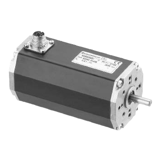
- Seite 1 Instruction Manual / Betriebsanleitung BLDC motor with integrated speed controller Bürstenloser DC-Motor mit integriertem Drehzahlregler BG 65 SI Edition / Ausgabe (05/2010)
-
Seite 2: Inhaltsverzeichnis
Page Seite 1 Contents 1 Inhalt 2 About this document 2 Über dieses Dokument 3 General description 3 Allgemeine Beschreibung 3.1 Motor series BG 65 SI 3.1 Motorbaureihe BG 65 SI 3.2 Explanations of terms used 3.2 Begriffserklärungen 3.3 Proper use 3.3 Bestimmungsgemäße Verwendung 3.4 Standards and guidelines 3.4 Normen und Richtlinien... - Seite 3 9 Operation hints 9 Betriebshinweise 9.1 Operation 9.1 Inbetriebnahme 9.2 Function of the digital inputs IN1 9.2 Funktion der Digitaleingänge IN1 and IN2 und IN2 9.3 Function of the digital inputs IN3 9.3 Funktion der Digitaleingänge IN3 and IN4 und IN4 9.4 Teaching of fixed speeds 9.4 Teachen von festen Geschwindigkeiten 27 9.5 Teaching of ramps...
-
Seite 4: About This Document
2 About this document 2 Über dieses Dokument These operating instructions introduce you to the SI Die vorliegende Betriebsanleitung stellt Ihnen die SI- drives and provide you with information on all the Antriebe vor und informiert Sie über alle Schritte zur stages required for the installation of the drives and Installation der Antriebe und zur Durchführung von the performance of functional tests. -
Seite 5: General Description
3 General description 3 Allgemeine Beschreibung 3.1 Motor series BG 65 SI 3.1 Motorbaureihe BG 65 SI The motor type BG 65 SI represents EC-motors Bei der Motorbaureihe BG 65 SI handelt es sich um (brushless DC motor) with an integrated speed control EC-Motoren (bürstenlose DC-Motoren) mit ange- electronic for 4-quadrant operation. -
Seite 6: Explanations Of Terms Used
3.2 Explanations of terms used 3.2 Begriffserklärungen Component for the transfor- Bauteil zur Umwandlung von Brückengleichrich- Bridge rectifier mation from AC voltage to DC Wechselspannung in Gleich- voltage spannung Smoothing capaci- Component to smooth the Glättungskonden- Bauteil Glättung fluctuation voltage sator Spannungsschankungen Sensor zur Positionsbestim-... -
Seite 7: Standards And Guidelines
3.4 Standards and guidelines 3.4 Normen und Richtlinien EU guidelines: the EU guidelines formulate the mi- EG-Richtlinien: Die EG-Richtlinien formulieren die nimum requirements made on a product and must be Mindestanforderungen an ein Produkt und müssen observed by all manufacturers and dealers marketing von allen Herstellern und Händlern beachtet werden, the product in the member states of the European die das Produkt in den Mitgliedstaaten der Europä-... -
Seite 8: Safety Instructions
4 Safety instructions 4 Sicherheitshinweise Vor der Inbetriebnahme sind unbe- Before commissioning, it is dingt die Sicherheitshinweise zu lesen essential that the safety instructions und zu beachten! Eine Nichtbeach- in the relevant section are read and tung kann zu Gefahren bei Personen understood, and then observed! WARNING WARNUNG... -
Seite 9: Technical Data, Accessories
5 Technical data, accessories 5 Technische Daten, Zubehör 5.1 Electrical data 5.1 Elektrische Daten Maximum motor speed Ungeregelter 0 ... 7000 U/min 0 ... 7000 U/min range Drehzahlbereich Speed range Regelbarer Drehzahl- 70 ... 4096 U/min 70 ... 4096 U/min adjustable bereich Minimum motor... -
Seite 10: Mechanical Data
5.2 Mechanical data 5.2 Mechanische Daten Temperature range -20 °C ... +100 °C Temperaturbereich -20°C…+100°C motor housing temperature Motor Gehäusetemperatur Recommended environ- Empfohlener Umge- 0 °C ... 50 °C 0°C…50°C mental temperature range *) bungstemperaturbereich *) Relative humidity Relative Max. 90% Max. -
Seite 11: Motor Bg 65X25 Si
5.4 Motor BG 65x25 SI 5.4 Motor BG 65x25 SI 65 W 65 W Nominal power Nennleistung 17(21*) Ncm 17(21*) Ncm Nominal torque *) Nenndrehmoment *) 3100 3100 Rated speed Nenndrehzahl 24 V (standard), special 24 V (Standard), Sonder- Nominal supply voltage Nennspannung voltage on request spannung auf Anfrage... -
Seite 12: Accessories
5.7 Accessories 5.7 Optionale Anbauten Incremental transmitter (RE) Inkrementalgeber (RE) Transmitter pulses 500 (other pulses Geberimpulse 500 (andere Impuls- available upon request) zahlen auf Anfrage) Transmitter channels Geberkanäle Index pulse Indeximpuls Construction Assembled in the profile Bauform Hinten am Motor in Pro- casing at the rear, on the filgehäuse montiert motor... -
Seite 13: Protective Functions
6 Protective functions 6 Schutzfunktionen The objective of protective functions is to protect the Schutzfunktionen dienen dem Schutz des Motors motor from damage, e.g. due to external loading or vor Zerstörung z.B. bei extremer Belastung oder bei excessive voltage. Spannungsüberhöhungen. 6.1 Ballastschaltung 6.1 Ballast circuit Bei Bremsvorgängen wird die kinetische Energie als... -
Seite 14: Mechanische Montage
7 Installation / terminal assignment 7 Installation und Anschlussbelegung Vor der Inbetriebnahme sind unbe- Before commissioning, it is dingt die Sicherheitshinweise zu lesen essential that the safety instructions und zu beachten! Eine Nichtbeach- in the relevant section are read and tung kann zu Gefahren bei Personen understood, and then observed! WARNING... -
Seite 15: Electromechanical Compatibility
7.2 Electromechanical compatibility 7.2 Elektromagnetische Verträglichkeit Electromagnetic radiated interferences occur in the Beim Antrieb BG 65 SI und bei der Maschine, in drive BG 65 SI and the machine in which the drive welche der Antrieb eingebaut wird, entstehen elek- is installed. -
Seite 16: Connection Alternatives
7.4 Connection alternatives 7.4 Anschlussmöglichkeiten In the following, the standard connection types with Im folgenden werden die Standardanschlussarten mit 12-pole connectors are described again explicitly. 12-pol. Stecker nochmals explizit dargestellt. The alternative with 12-pole connector offers the Die Variante mit 12-pol. Stecker bietet den größten grea-test functional range including teaching of 2 fixed Funktionsumfang einschließlich dem Abspeichern speeds as well as run-up ramp and break ramp, and... -
Seite 17: Connection 24 V-Motors
7.5.1 Connection 24 V-motors 7.5.1 Anschluss 24 V-Motoren Signale / Signals (E/A): Versorgung / Supply: +24 V DC GND (0V) 7.5.2 Connection 42 V-motors 7.5.2 Anschluss 42 V-Motoren Signale / Signals (E/A): Versorgung / Supply: Leistung / Power Logik / Logic +24 V DC +42 V DC GND (0V) -
Seite 18: Connection Via 12-Pin Connector For 24-Motors
7.5.3 Connection via 12-pin connector for 7.5.3 Anschluss über 12-pol. Stecker für 24-motors 24 V-Motoren Con- Con- Function Strand colour Ste- Funktion Litzenfarbe nec- nec- of the connec- cker- schluss der Anschluss- tor- tion ting cable with leitung mit 12 12-pole angu- pol. -
Seite 19: Connection Via 12-Pin Connector For 42 V-Motors
7.5.4 Connection via 12-pin connector for 7.5.4 Anschluss über 12-pol. Stecker für 42 V-motors 42 V-Motoren Connec- Connec- Function Strand colour Stecker- Funktion Litzenfarbe tor-Pin tion of the con- schluss der An- necting cable schlusslei- with 12-pole tung mit 12 angular con- pol. -
Seite 20: Schematic Circuit Of The Digital Outputs
7.6 Schematic circuit of the digital outputs 7.6 Prinzipschaltung der Digitalausgänge Ausgang Output Mit max. Chargeable 12 mA with max. belastbar 12 mA. 7.7 Prinzipschaltung der Digitaleingänge 7.7 Schematic circuit of the digital inputs Mating connector with cable (please order in addition): Gegenstecker mit Anschlußleitung ( bitte mitbestellen): Adequate connector cables with different standard Für die Motoren BG 65 SI mit seitlichem Anschluss-... -
Seite 21: Maximum Cable Length And Power Supply
Option (angled positions adjustable) Option (Winkelposition einstellbar) Standard (angled positions not adjustable) Standard (Winkelposition nicht einstellbar) 7.8 Maximum cable length and 7.8 Maximale Kabellängen und power supply Spannungsversorgung If the supply of power and logic Erfolgt die Versorgung von electronic is procceded by a Leistungs- und Logikteil durch eine common 24V DC power source, a safe gemeinsame 24V DC Spannungs-... - Seite 22 If the supply of power and logic electronic Erfolgt die Versorgung von Leistungs- und Lo- is procceded by separate power sources, gikteil durch getrennte Spannungsquellen, sind the following cable lengths are available: folgende Leitungslängen lieferbar: Length Länge 1.5 m 1,5 m 10 m 10 m Instruction Manual/Betriebsanleitung BG 65 SI, Version: 1.3 en_de...
-
Seite 23: Connection Schematic
8 Connection schematic 8 Anschlussschema Vor der Inbetriebnahme sind unbe- Before commissioning, it is dingt die Sicherheitshinweise zu lesen essential that the safety instructions und zu beachten! Eine Nichtbeach- in the relevant section are read and tung kann zu Gefahren bei Personen understood, and then observed! WARNING WARNUNG... -
Seite 24: Prinzipschaltbild Spannungs- Versorgung Regler/ Motor Bg65 Si
8.1 Schematic circuit for power 8.1 Prinzipschaltbild Spannungs- supply controller/ motor versorgung Regler/ Motor BG65 SI BG65 SI Peak current by switching-on of a Stromspitzen beim Einschalten variety of series-connected mehrerer hintereinander geschal- motors! teter Motoren! Consequence: Die Folge: CAUTION VORSICHT Destroying of the integrated electronics Die integrierte Elektronik kann zerstört... -
Seite 25: Operation Hints
9 Operation hints 9 Betriebshinweise 9.1 Operation 9.1 Inbetriebnahme Vor der Inbetriebnahme sind unbe- Before commissioning, it is dingt die Sicherheitshinweise zu lesen essential that the safety instructions und zu beachten! Eine Nichtbeach- in the relevant section are read and tung kann zu Gefahren bei Personen understood, and then observed! WARNING... -
Seite 26: Function Of The Digital Inputs In1 And In2
9.2 Function of the digital inputs IN1 and IN2 9.2 Funktion der Digitaleingänge IN1 und IN2 With the help of the two digital inputs IN1 and IN2, Mit Hilfe der beiden digitalen Eingänge IN1 und IN2 altogether 4 operating conditions can be triggered, lassen sich insgesamt 4 Betriebszustände ansteuern, because of the fact that to each of the both inputs the da jedem der beiden Eingänge die logischen Zustän-... -
Seite 27: Teaching Of Fixed Speeds
The following operating conditions can be triggered: Die folgenden Betriebszustände können angesteuert werden: Function Funktion Controlled motor speed mode Drehzahlregelbetrieb (70 ... 4096 rpm adjustable via (70 ... 4096 rpm über Analogein- analogue input) gang einstellbar) Uncontrolled operation (70 ... Ungeregelter Betrieb approx. -
Seite 28: Teaching Of Ramps
9.5 Teaching of ramps 9.5 Teachen von Rampen In case the motor provides the option (inputs IN3, IN4 Falls der Motor die Option bietet (Eingänge IN3, IN4 lead through), the acceleration and braking ramp can herausgeführt), können die Beschleunigungs- und be adjusted by “teaching”. - Seite 29 (Volt) z = 1024 * U /10 T (ms) per (Volt) z = 1024 * U /10 T (ms) pro (number) 1000 rpm (Zahl) 1000 rpm 20000 20000 16004 16004 12008 12008 8012 8012 4016 4016 2018 2018 1019 1019 1004 419,6 1004...
-
Seite 30: Function Of The Pulse Output Out1
9.6 Function of the pulse output OUT1 9.6 Funktion des Pulsausgangs OUT1 The pulse output OUT1 provides 15 impulses per motor Der Pulsausgang OUT1 liefert 15 Impulse pro Motor- turn, whereas the pulse duration t and the pulse brake umdrehung, wobei die Pulsdauer t und die Pul- is motor speed addicted. -
Seite 31: Protective Functions And Fault Output Out3
9.7 Protective functions and fault output 9.7 Schutzfunktionen und Meldeausgang OUT3 OUT3 The motor is equipped with the following Der Motor ist mit folgenden Schutzfunktionen ausge- protective functions: stattet: • Excessive temperature protection • Übertemperatur • Undervoltage protection • Unterspannung The protective functions serve as motor protection Die Schutzfunktionen dienen dem Schutz des Motors against destruction at extreme loading. -
Seite 32: Function Of The Analogue Input Ai+/Ai
9.8 Function of the analogue input AI+/AI- 9.8 Funktion des Analogeinganges AI+/AI- The input circuit of the analogue input is designed Die Eingangsschaltung des Analogeingangs ist als as differential amplifier with an input resistance of 100 Differenzverstärker mit einem Eingangswiderstand kOhm. -
Seite 33: Motors With Additional Brake
9.9 Motors with additional brake 9.9 Motoren mit zusätzlicher Bremse High wear of contact material and Kontaktabbrand und Spannungs- energy intense voltage peaks by using spitzen bei Motoren mit a motor with attached brake! angebauter Bremse! Consequence: Die Folge: CAUTION VORSICHT Destroying of electrical components Zerstörung elektrischer Bauteile... -
Seite 34: Maintenance & Service
Rotor stop brake with 6-pole connector plug Ankerstoppbremse mit 6-pol. Anschlussstecker Connection Anschluss +24 V for brake +24 V für Bremse 0 V for brake 0 V für Bremse n.c. n.c. n.c. n.c. n.c. n.c. n.c. n.c. 10 Maintenance & Service 10 Wartung &... -
Seite 35: Service & Support
Taking out of service: Ausserbetriebsetzung: The safety instructions must be read Vor der Ausserbetriebnahme sind and observed prior to taking unbedingt die Sicherheitshinweise the unit out of service! zu lesen und zu beachten! NOTICE HINWEIS Disposal: Entsorgung: Take the drive out of service (see above). Dismantle Setzen Sie den Antrieb ausser Betrieb (s.o.). -
Seite 36: Appendix
11 Anhang 11 Appendix Dieses Kapitel enthält folgende ergänzende Unterla- This chapter contains supplementary documents, gen, die von der Dunkermotoren GmbH provided by Dunkermotoren GmbH or external oder Drittlieferanten bereitgestellt wurden: suppliers: A) CE-Herstellererklärung A) CE-declaration of the manufacturer CE - Konformitätserklärung CE - Declaration of Conformity Hersteller: Dunkermotoren GmbH Manufacturer: Dunkermotoren GmbH... - Seite 37 Notes Notizen...
- Seite 38 Notes Notizen...