Inhaltsverzeichnis
Werbung
Quicklinks
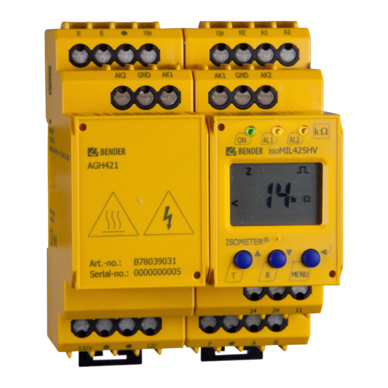
ISOMETER® isoMIL425HV mit Ankoppel-
gerät/with coupling device AGH421
Isolationsüberwachungsgerät für ungeerdete AC-, AC/DC- und DC-
Stromversorgungen (IT-Systeme) für militärische Anwendungen bis
3(N)AC, AC 690 V, DC 1000 V
Insulation monitoring device for unearthed AC-, AC/DC and DC systems
(IT systems) in military applications up to 3(N)AC, AC 690 V, DC 1000 V
isoMIL425HV_D00204_05_Q_DEEN / 02.2021
Kurzanleitung/Quickstart guide DE/EN
Werbung
Inhaltsverzeichnis

Inhaltszusammenfassung für Bender ISOMETER isoMIL425HV
- Seite 1 ISOMETER® isoMIL425HV mit Ankoppel- gerät/with coupling device AGH421 Isolationsüberwachungsgerät für ungeerdete AC-, AC/DC- und DC- Stromversorgungen (IT-Systeme) für militärische Anwendungen bis 3(N)AC, AC 690 V, DC 1000 V Insulation monitoring device for unearthed AC-, AC/DC and DC systems (IT systems) in military applications up to 3(N)AC, AC 690 V, DC 1000 V isoMIL425HV_D00204_05_Q_DEEN / 02.2021 Kurzanleitung/Quickstart guide DE/EN...
- Seite 2 Kurzanleitung beiliegenden this quickstart is the enclosed “Safety instructions „Sicherheitshinweise für Bender-Produkte“ und for Bender products“ and the manual, which can das Handbuch, herunterladbar unter https:// be downloaded from https://www.bender.de/en/ www.bender.de/service-support/downloadbe- service-support/downloads.The quickstart does reich. Die Kurzanleitung ersetzt nicht das not replace the manual.
-
Seite 3: Montage
Montage Mounting Click & Click! isoMIL425HV_D00204_05_Q_DEEN / 02.2021... -
Seite 4: Wiring Diagram
Anschlussbild Wiring diagram L1/+ L2/- Stop GND AK2 > 800 V 30 mm 30 mm AGHxxx isoMIL425HV AGH421 ISOMETER® MENU L1/+ L2/- COM465IP L1/+ L2/- RS-485 Legend Legende Klemme/Terminal Anschlüsse Connections Anschluss an die Versorgungsspannung U über Schmelz- Connection to the supply voltage U via fuse (line protection): A1, A2 sicherung (Leitungsschutz):... -
Seite 5: Menü-Übersicht
Menü-Übersicht Menu overview > < 1.5 s > > 1.5 s 1.5 s . . . < t > 5 Min. < > 1.5 s Z [kΩ] R [kΩ] C [µF] U L1 L2 [V ] < UL1 [V ] >... -
Seite 6: Display Elements
Display-Elemente Display elements Funktion Gerätefront/ Device front Function grün - On green - On gelb - Alarm yellow - Alarm gelb - Alarm yellow - Alarm Aufwärts-Taste Up button Test-Taste (> 1,5 s drücken) Test button (press > 1.5 s) Bei gedrückter Test-Taste werden die By pressing and holding the test Display-Elemente angezeigt. - Seite 7 Inbetriebnahme Commissioning 1. Prüfen auf korrekten Anschluss des ISOMETER®s an 1. Check that the ISOMETER® is properly connected to das zu überwachende Netz. the system to be monitored. 2. Versorgungsspannung U für ISOMETER® zuschal- 2. Connect the supply voltage U to the ISOMETER®.
-
Seite 8: Error Codes
Fehlercodes Error codes Fehlercode/Error code Bedeutung Meaning Anschlussfehler PE PE connection error Die Verbindung der Anschlüsse „E“ oder „KE“ zu Erde ist The connections „E“ or „KE“ to earth are interrupted. unterbrochen. Action: E.01 Maßnahme: Check connection, eliminate error. The error code will be Anschluss prüfen, Fehler beseitigen. -
Seite 9: Technische Daten
Technische Daten Technical data Isolationskoordination nach IEC 60664-1/IEC 60664-3 Insulation coordination acc. to IEC 60664-1/IEC 60664-3 Bemessungsspannung ..............240 V Rated voltage ................. 240 V Überspannungskategorie ..............III Overvoltage category ................III Versorgungsspannung Supply voltage Versorgungsspannung U ...... AC 100…240 V/DC 24…240 V Supply voltage U ........ - Seite 10 Umwelt/EMV Environment/EMC EMV ............ IEC 61326-2-4, DIN EN50121-3-2 EMC ............. IEC 61326-2-4, DIN EN50121-3-2 Umgebungstemperaturen: Ambient temperatures: Betrieb ................-40…+70 ºC Operation ................-40…+70 ºC Transport ................-50…+85 ºC Transport ................-50…+85 ºC Lagerung................-55…+80 ºC Storage ................-55…+80 ºC Klimaklassen nach IEC 60721: Climatic class acc.
- Seite 11 Umwelt/EMV Environment/EMC EMV ..................IEC 61326-2-4 EMC ...................IEC 61326-2-4 Umgebungstemperaturen: Ambient temperatures: Betrieb ................-40…+70 °C Operation ................-40…+70 °C Transport ................-50…+85 °C Transport ................-50…+85 °C Lagerung................-55…+80 °C Storage ................-55…+80 °C Klimaklassen nach IEC 60721: Classification of climatic conditions acc. to IEC 60721 Ortsfester Einsatz (IEC 60721-3-3) ..........
-
Seite 12: Normen, Zulassungen Und Zertifizierungen
Nachdruck und Vervielfältigung Reprinting and duplicating nur mit Genehmigung des Herausgebers. only with permission of the publisher. Bender GmbH & Co. KG Bender GmbH & Co. KG Postfach 1161 • 35301 Grünberg • Deutschland PO Box 1161 • 35301 Grünberg • Germany Londorfer Str.


