Werbung
Verfügbare Sprachen
Verfügbare Sprachen
Quicklinks
ISM-95 Isolator Module Installation Sheet
EN DE ES FR NL PL
1
EN: Installation Sheet
Description
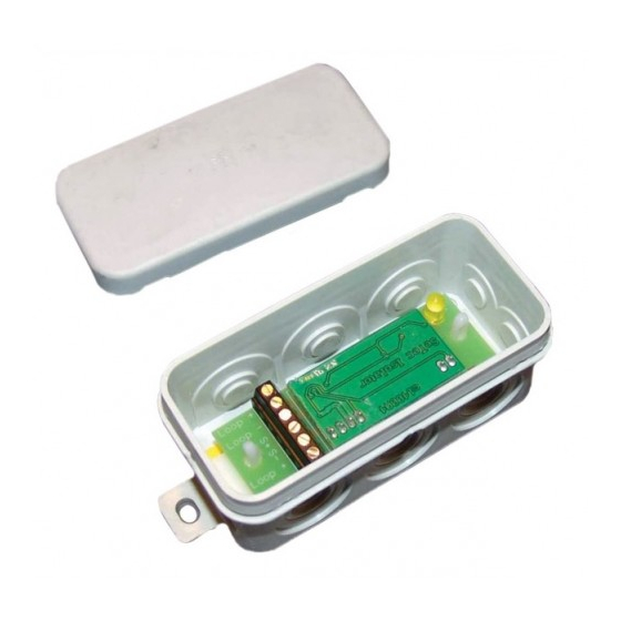
The ISM-95 Isolator Module provides short circuit protection for
an addressable loop. When a short circuit is detected on the
fire panel loop on either side of the isolator, that side will be
isolated and the yellow "isolated" LED will turn on. When the
short clears, the isolator automatically resets and reconnects
the loop.
If required, one additional device can be connected to a short
spur connection. A device connected to the short spur
connection will continue to receive power from the one side of
the loop and remain operational in case of a short circuit on the
loop. A short circuit on the spur will short circuit both sides of
the loop (bypass the isolator).
Installation
The ISM-95 is designed for use in dry environments. The
module is supplied in an IP55 enclosure. Mount the enclosure
at a suitable location, and then connect the field wiring in
accordance with "Connections."
Connections
The incoming addressable loop can be connected to either set
of Loop + and Loop – terminals (1 and 2 or 5 and 6) shown in
Figure 1.
The outgoing addressable loop is connected to the remaining
set of Loop + and Loop – terminals (5 and 6 or 1 and 2). Do not
mix connections between the incoming and outgoing.
© 2011 UTC Fire & Security. All rights reserved.
PT RU
If an additional device is to be used on a spur, it must be
connected to terminals S+ and S– shown in Figure 1.
Figure 1 shows connections for the ISM-95.
1.
Loop +
2.
Loop –
3.
Spur connection+ (S+)
4.
Spur connection– (S–)
5.
Loop +
6.
Loop –
7.
Isolator LED
Maintenance
The only maintenance required is a yearly inspection. Do not
modify the internal wiring or circuitry.
Specifications
Operating temperature
Operating voltage
Switching voltage
(normal to isolated)
IP rating
Dimensions (W × H × D)
Weight
1 / 2
0 to +50°C
24 VDC
13.8V
IP55
43 × 89 × 37 mm
147 g
P/N 3101877 • REV 1.0 • ISS 14JUN11
Werbung

Inhaltszusammenfassung für Aritech ISM-95
- Seite 1 Installation Operating temperature 0 to +50°C Operating voltage 24 VDC The ISM-95 is designed for use in dry environments. The Switching voltage 13.8V module is supplied in an IP55 enclosure. Mount the enclosure (normal to isolated) at a suitable location, and then connect the field wiring in accordance with “Connections.”...
-
Seite 2: Wartung
Ringleitung kurz geschlossen (Umgehung des Isolators). Kontaktinformationen Montage Kontaktinformationen finden Sie auf www.utcfireandsecurity.com. Das ISM-95 wurde für den Einsatz in trockenen Umgebungen konzipiert. Das Modul wird in einem IP55-Gehäuse geliefert. ES: Hoja de instalación Montieren Sie das Gehäuse an einer geeigneten Stelle und klemmen Sie anschließend die Feldverkabelung gemäß... - Seite 3 Instalación Información de contacto Para obtener información de contacto, consulte El módulo ISM-95 está diseñado para uso en entornos secos. www.utcfireandsecurity.com. El módulo viene dentro de una caja IP55. Instale la caja en una ubicación adecuada y conecte el cableado de instalación de acuerdo con “Conexiones”.
- Seite 4 S+ en S–, (normale à isolée) zoals in afbeelding 1 wordt getoond. Indice IP IP55 In afbeelding 1 worden de aansluitingen voor de ISM-95 Dimensions (lxHxP) 43 × 89 × 37 mm getoond. Poids...
-
Seite 5: Konserwacja
Na Rysunku 1 pokazano opis zacisków modułu ISM-95. Instalação Pętla + Pętla – O ISM-95 foi concebido para utilização em ambientes secos. O Urządzenie + (S+) módulo é fornecido numa caixa IP55. Instale a caixa numa Urządzenie – (S–) localização adequada, e ligue o cabo da instalação em Pętla +... - Seite 6 EN 54-17 B11066 Идентификатор статьи Установка Модуль ISM-95 предназначен для использования в сухой Контактная информация среде. Модуль поставляется в корпусе класса защиты IP55. Установите корпус в подходящем месте и затем Для получения контактной информации посетите сайт: подсоедините шлейфовую проводку в соответствии с...


