Inhaltsverzeichnis
Werbung
Quicklinks
ORIGINAL INSTRUCTIONS
ENGINEERS, AND ILLUSTRATED PARTS MANUAL
ORIGINALBETRIEBSANLEITUNG
WARTUNGSANLEITUNG UND ILLUSTRIERTES TEILEVERZEICHNIS
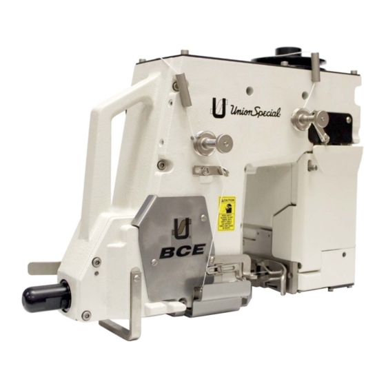
BCE200 MEDIUM SPEED BAG CLOSING MACHINES
CORROSION RESISTANT PARTS
BCE200 "ECONOMY" SACKZUNÄHMASCHINEN
KORROSIONSGESCHÜTZTE TEILE
MANUAL NO. / KATALOG NR. PT1202-GR EN-DE
FOR SERIES / FÜR KLASSEN
BCE200
10.2013
Werbung
Inhaltsverzeichnis

Verwandte Anleitungen für Union Special BCE200 Serie


Inhaltszusammenfassung für Union Special BCE200 Serie
- Seite 1 ORIGINAL INSTRUCTIONS ENGINEERS, AND ILLUSTRATED PARTS MANUAL ORIGINALBETRIEBSANLEITUNG WARTUNGSANLEITUNG UND ILLUSTRIERTES TEILEVERZEICHNIS BCE200 MEDIUM SPEED BAG CLOSING MACHINES CORROSION RESISTANT PARTS BCE200 “ECONOMY” SACKZUNÄHMASCHINEN KORROSIONSGESCHÜTZTE TEILE MANUAL NO. / KATALOG NR. PT1202-GR EN-DE FOR SERIES / FÜR KLASSEN BCE200 10.2013...
- Seite 2 BCE200 SERIES MACHINES Erste Auflage © 2012 First Edition Copyright 2012 Weltweit beanspruchte Union Special GmbH Rechte Union Special GmbH Rights Reserved in All Countries VORWORT PREFACE Dieser Katalog wurde zusammengestellt, um Ersatz- This manual has been prepared to simplify ordering teilbestellungen zu vereinfachen.
-
Seite 3: Inhaltsverzeichnis
PAGE / SEITE TABLE OF CONTENTS TABLE OF CONTENTS TABLE OF CONTENTS TABLE OF CONTENTS TABLE OF CONTENTS INHALTSVERZEICHNIS INHALTSVERZEICHNIS INHALTSVERZEICHNIS INHALTSVERZEICHNIS INHALTSVERZEICHNIS Transporteur-Einstellung Feed Dog Setting Drückerfuß- und Kettelteildruck Presser Foot and Chaining Section Pressure Greifer-Einstellung Looper Setting Nadelhöhen-Einstellung Needle Height Setting Nadelanschlag-Einstellung Needle Guard Setting... -
Seite 4: Identification Of Machines
IDENTIFICATION OF MACHINES BEZEICHNUNG DER MASCHINEN Each UNION SPECIAL BCE200 series machine is iden- Jede UNION SPECIAL BCE200 Maschine hat eine tified by a style number, which is stamped on the style Typnummer, die in das Typenschild eingeprägt ist, das plate located on the center portion at the rear of the mittig an der hinteren Gehäuseseite befestigt ist. - Seite 5 Medium speed and high performance automatic sewing „Economy“ Automatik-Nähmaschinen mit automatischem machines with automatic start and stop of the machine Start und Stopp der Maschine und automatisch arbeitenden and automatically operated thread chain or tape cutters for Fadenketten– oder Bandabschneidern zum Schliessen ge- closing filled bags and sacks made of jute, cotton, paper, füllter Säcke und Beutel aus Jute, Baumwolle, Papier, plastic or woven polypropylene tapes, bituminized or foil-...
-
Seite 6: Types Of Bag Closures
BCE211UA26-1M: Sewing machine for closing filled bags BCE211UA26-1M: Nähmaschine zum Zunähen gefüllter and sacks made of paper or plastic foil (minimum thickness Säcke und Beutel aus Papier oder Plastikfolie (Mindeststärke of foil .007 in. (0.18 mm) with a two thread double locked der Folie 0,18 mm) mit einem Zweifaden-Doppelkettenstich, stitch, and simultaneously binding the bag mouth with a 2"... - Seite 7 NEEDLES NADELN Each needle has both a type and a size number. The Jede Nadel hat eine Typ- und eine Dickennummer. Die type number denotes the kind of shank, point, length, Typnummer bezeichnet die Art des Nadelkolbens, der groove, finish and other details. The size number, Spitze, Länge, Rinne, Oberfläche und andere Einzel- stamped on the needle shank, denotes the largest...
-
Seite 8: Safety Rules
SAFETY RULES SICHERHEITSHINWEISE Before putting the machine described in this manual Lesen Sie vor Inbetriebnahme der in diesem Katalog into service, carefully read the instructions. The beschriebenen Maschine die Betriebsanleitung sorg- starting of each machine is only permitted after fältig. Jede Maschine darf erst nach Kenntnisnahme der taking notice of the instructions and by qualified Betriebsanleitung und nur durch entsprechend unter- operators. - Seite 9 Personen unter Beachtung der instructions. Only genuine spare parts approved by Betriebsanleitung durchgeführt werden. Für Repara- Union Special have to be used for repairs. turen sind nur die von Union Special freigegebenen Original-Ersatzteile zu verwenden. 10. Any work on the electrical equipment must be done 10.
-
Seite 10: Threading The Machine
EINFÄDELN DER MASCHINE THREADING THE MACHINE Schalten Sie vor dem Einfädeln den Haupt- Turn off main power switch before schalter aus! Beim Gebrauch von threading! When using clutch motors Kupplungsmotoren ohne Betätigungs- without actuation lock wait until motor sperre ist der Stillstand des Motors abzu- has completely stopped. -
Seite 11: Inserting Needle
INSERTING NEEDLE EINSETZEN DER NADEL The standard needle is 9848GF 250/100. Insert needle Die Standardnadel ist 9848GF 250/100. Setzen Sie die according to the following procedure: Nadel wie folgt ein: Bring needle head (A) to the highest position. Bringen Sie den Nadelkopf (A) in die obere Stellung. Loosen screw (B). - Seite 12 Maschine abgelassen, der Ölbehälter muss deshalb vor to operate. Use the oil with UNION SPECIAL Specification der Inbetriebnahme gefüllt werden. Verwenden Sie das im No. 175 which is delivered with the accessories of the Zubehör der Maschine mitgelieferte Öl mit der UNION...
- Seite 13 LUBRICATION (CONT.) ÖLEN (FORTS.) 3. The 5mm Allen head oil drain screw (C) is located on 4. Die 5 mm Innensechskant-Öl-Ablassschraube (C )befin- the back cover next to DRAIN on the cover. det sich an der hinteren Abdeckung neben dem Wort DRAIN auf der Abdeckung.
-
Seite 14: Oil Flow Diagram
OIL FLOW DIAGRAM ÖLFLUSS-DIAGRAMM The oiling system consists of pressurized oil that is sent Die Druckschmierung arbeitet mit Drucköl, das intern an die to strategic areas internally throughout the machine that strategisch wichtigen Stellen der Maschine, die Öl benötigen, require oil. First the oil travels from the oil chamber on the geleitet wird. -
Seite 16: Oil Specification Requirements
(will not thin down excessively with hoher Viskosität sein (verdünnen sich bei Hitze nicht über- heat). Practically all oil companies have Union Special mäßig). Praktisch alle Ölgesellschaften haben Öle entspre- Specification 175 and their industrial representatives will chend der Union Special Öl-Spezifikationen 175 und ihre... - Seite 18 MAINTENANCE PLAN BC BCE200 Daily at the beginning of shift work 1. Check oil level at oil gauge glass after closing 30 to 40 bags.. 2. Check oil flow at running machine; splash oil has to be visible at the oil sight glass. Ölspiegel zwischen Markierungen ok Oil Level between...
- Seite 19 WARTUNGSPLAN BCE200 Täglich bei Schichtbeginn: 1. Ölspiegel im Ölschauglas nach 30 bis 40 Säcken kontrollieren. 2. Ölflusskontrolle bei laufender Maschine; Spritzöl im Ölschauglas muss sichtbar sein. Ölspiegel zwischen Markierungen ok Oil Level between markings ok Täglich bei Schichtende: Nähmaschine mit Pressluft reinigen!! Zum Reinigen die Greiferabdeckung und die Greiferfadenab- deckung öffnen.
-
Seite 20: Adjusting The Stitch Length
ADJUSTING THE STITCH LENGTH STICHLÄNGEN-EINSTELLUNG Stitch length is set at the factory at 3SPI (8 mm). If Die Stichlänge ist in der Fabrik auf 8 mm eingestellt. adjustment is necessary: Falls eine Einstellung notwendig ist, gehen Sie wie folgt vor: 1. -
Seite 21: Feed Dog Setting
FEED DOG SETTING TRANSPORTEUR-EINSTELLUNG Stellen Sie die Höhe des Transporteurs in seiner höchsten Set the height of the feed dog in its highest position so that the rear teeth project .060" (1.5 mm) above the throat plate Stellung so ein, daß die hinteren Zähne 1,5 mm aus der Stichplatte ragen. -
Seite 22: Looper Setting
LOOPER SETTING GREIFER-EINSTELLUNG Set the looper so that the looper point is .196" (5 mm) from Stellen Sie den Greifer so ein, daß der Abstand von Mitte the centerline of the needle, when the looper is at its Nadel bis zur Spitze des Greifers 5 mm beträgt, wenn der furthest position to the right. -
Seite 23: Needle Guard Setting
NEEDLE GUARD SETTING NADELANSCHLAG-EINSTELLUNG 1. Attach fixed rear needle guard to rubber seal frame. 1. Befestigen Sie den feststehenden hinteren Nadelan- schlag am Gummidichtrahmen. 2. Rotate pulley in operating direction until the point of 2. Drehen Sie die Riemenscheibe bis die Greiferspitze the looper is just entering the scarf of the needle. -
Seite 24: Looper Thread Control
LOOPER THREAD CONTROL GREIFERFADENKONTROLLE 1. Set the looper thread take up lever to just contact the 1. Stellen Sie den Greiferfadenabzugshebel so ein, thread when the needle enters the throat plate. dass er gerade den Faden berührt, wenn die Nadel- spitze sich an der Oberkante der Stichplatte befindet. -
Seite 25: Stitch Formation And Thread Tension
STITCH FORMATION AND THREAD TENSION STICHBILDUNG UND FADENSPANNUNG Set the needle thread tension to be light enough to maintain Stellen Sie die Nadelfadenspannung so ein, daß bei Bildung a needle loop at the tip of the needle on half the length of one einer halben Stichlänge eine ausreichend große Nadel- stitch. -
Seite 26: Mounting The Proximity Switch For Feeler
STYLES BCE211P16-1M, UA26-1M KLASSEN BCE211P16-1M, UA26-1M MOUNTING THE PROXIMITY SWITCH FOR EINBAU DES NÄHERUNGSSCHALTER FÜR TASTER FEELER Entfernen Sie das linke Abschlußblech. Montieren Sie den Remove left end cover. Mount the electronic proximity elektronischen Näherungsschalter (A), wie in der Figur 1 switch (A) as shown in Fig. -
Seite 28: Scissors Type Thread Chain Cutter Setting
STYLES BCE211P15-1, BCE211P16-1M, -1A AND -1B: KLASSEN BCE211P15-1, BCE211P16-1M, -1A UND - SCISSORS TYPE THREAD CHAIN CUTTER SETTING FADENKETTENSCHEREN-EINSTELLUNG When the air cylinder for the chain cutter (R, Fig. 1) is not activated and the chain cutter (R) is in its home position Wenn der Luftzylinder für die Kettenschere (R, Fig. -
Seite 29: Setting The Time Relays In The Switch Box Of The
D3 in the switch Anhalten des Motors kann am Verzögerungsrelais D3 im box of the UNION SPECIAL sewing station 20600 div. BC. Schaltkasten der UNION SPECIAL Nähstation 20600 div. BC eingestellt werden. -
Seite 30: Wiring Diagram
WIRING DIAGRAM SCHALTSCHEMA STYLES BCE211P16-1M, -1A, -1B KLASSEN BCE211P16-1M, -1A, -1B Pay attention to the numbers on contact Beachten Sie beim Anschließen der Ka- insert of plug when connecting the cable beladern die Ziffern am Kontrakträger leads. des Steckers. When assembling the plug choose built- Wählen Sie beim Zusammenbau des in position “A”... - Seite 31 STYLES BCE211UA25-1 AND UA26-1M KLASSEN BCE211UA25-1 UND UA26-1M C29476GC6 EINSTELLUNG DES GUILLOTINEBANDAB- C29476GC6 GUILLOTINE CUTTER ADJUSTMENTS SCHNEIDERS SLIDE BLOCK / GUIDE SETTING KNIFE ALIGNMENT MESSERAUSRICHTUNG With screws "C" just loosen enough to move the knife holder, Lockern Sie die Schrauben "C" gerade genug, um den move the cylinder and align the moving knife holder prongs Messerhalter zu bewegen, schieben Sie den Zylinder und so they are in the lower knife guide area.
- Seite 33 Synchronisieren mit Synchronisier-Teilesatz TT148 Synchronize with TT148 Synchronization Gauge Kit Entfernen Sie den Greifer und setzen Sie den Teststift Remove the looper and insert the test pin (I) , 1/4" (6.3 mm) (I), 6,3 mm Durchmesser x 44,5 mm lang, in den diameter x 1 3/4"...
- Seite 34 D3 in the switch box of the Schneidvorgang kann am Verzögerungsrelais D3 im Schalt- UNION SPECIAL sewing station 20600 div. BC. kasten der UNION SPECIAL Nähstation 20600 div. BC eingestellt werden. The switch box of the sewing stations includes an other Im Schaltkasten der Nähstation befindet sich ein weiteres...
- Seite 35 Ö a f l t s i . n i . t l l e t i e t c i f e l i ä i l h ä ä t n i Ö ö ä . t n t s i ä...
-
Seite 37: Views And Description Of Parts
VIEWS AND DESCRIPTION VIEWS AND DESCRIPTION VIEWS AND DESCRIPTION VIEWS AND DESCRIPTION VIEWS AND DESCRIPTION OF PARTS OF PARTS OF PARTS OF PARTS OF PARTS DARSTELLUNGEN UND DARSTELLUNGEN UND DARSTELLUNGEN UND DARSTELLUNGEN UND DARSTELLUNGEN UND TEILEBESCHREIBUNGEN TEILEBESCHREIBUNGEN TEILEBESCHREIBUNGEN TEILEBESCHREIBUNGEN TEILEBESCHREIBUNGEN... -
Seite 39: Bushings
BUSHINGS BUSHINGS BUSHINGS BUSHINGS BUSHINGS BUCHSEN BUCHSEN BUCHSEN BUCHSEN BUCHSEN Ref. No. Part No. Description Beschreibung Amt Req. Pos. Nr. Teil-Nr. Anzahl Nadelstangenbuchse 10044AL Bushing, needle bar, upper Nadelstangenbuchse 10054C Bushing, needle bar, lower Dichtungsring für 10054C 660-1137 “O” Ring for 10054C 10044BR Buchse, Drückerfußstange Bushing, presser bar... -
Seite 41: Needle Bar Drive
NEEDLE BAR DRIVE NEEDLE BAR DRIVE NEEDLE BAR DRIVE NEEDLE BAR DRIVE NEEDLE BAR DRIVE NADELSTANGENANTRIEB NADELSTANGENANTRIEB NADELSTANGENANTRIEB NADELSTANGENANTRIEB NADELSTANGENANTRIEB Ref. No. Part No. Description Beschreibung Amt Req. Pos. Nr. Teil-Nr. Anzahl Nadelstangenschutz 10096G Guard, needle bar Dichtungsring 660-1141 "O"Ring Nadelstange 10017B Needle Bar... -
Seite 43: Upper Main Shaft
UPPER MAIN SHAFT UPPER MAIN SHAFT UPPER MAIN SHAFT UPPER MAIN SHAFT UPPER MAIN SHAFT OBERE HAUPTWELLE OBERE HAUPTWELLE OBERE HAUPTWELLE OBERE HAUPTWELLE OBERE HAUPTWELLE Ref. No. Part No. Description Beschreibung Amt Req. Pos. Nr. Teil-Nr. Anzahl 10022F Main Shaft, upper Obere Hauptwelle TA0370601M0 Plug... -
Seite 45: Crankshaft Assembly
CRANKSHAFT ASSEMBLY CRANKSHAFT ASSEMBLY CRANKSHAFT ASSEMBLY CRANKSHAFT ASSEMBLY CRANKSHAFT ASSEMBLY KURBELWELLE, KOMPLETT KURBELWELLE, KOMPLETT KURBELWELLE, KOMPLETT KURBELWELLE, KOMPLETT KURBELWELLE, KOMPLETT Ref. No. Part No. Description Beschreibung Amt Req. Pos. Nr. Teil-Nr. Anzahl 10021S Pulley, adjustable Riemenscheibe, verstellbar 10095BL Screw, set Gewindestift 10084A Filzscheibe... -
Seite 47: Looper Drive
LOOPER DRIVE LOOPER DRIVE LOOPER DRIVE LOOPER DRIVE LOOPER DRIVE GREIFERANTRIEB GREIFERANTRIEB GREIFERANTRIEB GREIFERANTRIEB GREIFERANTRIEB Ref. No. Part No. Description Beschreibung Amt Req. Pos. Nr. Teil-Nr. Anzahl 10008 Looper Greifer C10008 Looper, chromium plated Greifer, verchromt (401 stitch) (401 Stich) 10008A Blind Looper (101 stitch) Einfachkettenstichgreifer (101 Stich) -
Seite 49: Feed Mechanism Transportmechanismus
FEED MECHANISM FEED MECHANISM FEED MECHANISM FEED MECHANISM FEED MECHANISM TRANSPORTMECHANISMUS TRANSPORTMECHANISMUS TRANSPORTMECHANISMUS TRANSPORTMECHANISMUS TRANSPORTMECHANISMUS Ref. No. Part No. Description Beschreibung Amt Req. Pos. Nr. Teil-Nr. Anzahl Schraube CSS6121050SP Screw C22894BP Screw Schraube Nadelanschlag 10025B Needle Guard C10034H Frame, sealing Dichtrahmen Dichtrahmen C10034E... -
Seite 51: Oil Pump
OIL PUMP OIL PUMP OIL PUMP OIL PUMP OIL PUMP ÖLPUMPE ÖLPUMPE ÖLPUMPE ÖLPUMPE ÖLPUMPE Ref. No. Part No. Description Beschreibung Amt Req. Pos. Nr. Teil-Nr. Anzahl Ölansaugrohr 10093CR Oil Tube, suction 660-3003 Rotary Fitting Schwenkverschraubung Halter für Ölrohr 10093T Clamp, oil tube WP0531000SE Washer... -
Seite 53: Oil Tubes
OIL TUBES OIL TUBES OIL TUBES OIL TUBES OIL TUBES ÖLSCHLÄUCHE ÖLSCHLÄUCHE ÖLSCHLÄUCHE ÖLSCHLÄUCHE ÖLSCHLÄUCHE Ref. No. Part No. Description Beschreibung Amt Req. Pos. Nr. Teil-Nr. Anzahl 10093AH Oil Tube, 220mm long Ölschlauch, 220mm lang 10093-4 Oil Tube, 178mml ong Ölschlauch, 178mm lang 10093-2 Oil Tube, 280mm long... -
Seite 55: Oil Distributor Assembly
OIL DISTRIBUTOR ASSEMBLY OIL DISTRIBUTOR ASSEMBLY OIL DISTRIBUTOR ASSEMBLY OIL DISTRIBUTOR ASSEMBLY OIL DISTRIBUTOR ASSEMBLY ÖLVERTEILER, KOMPLETT ÖLVERTEILER, KOMPLETT ÖLVERTEILER, KOMPLETT ÖLVERTEILER, KOMPLETT ÖLVERTEILER, KOMPLETT Ref. No. Part No. Description Beschreibung Amt Req. Pos. Nr. Teil-Nr. Anzahl Gasket Dichtung 10084 Oil Distributor Ölverteiler 10093CW... -
Seite 57: Presser Foot Lift Drückerfussliftung
PRESSER FOOT LIFT PRESSER FOOT LIFT PRESSER FOOT LIFT PRESSER FOOT LIFT PRESSER FOOT LIFT DRÜCKERFUSSLIFTUNG DRÜCKERFUSSLIFTUNG DRÜCKERFUSSLIFTUNG DRÜCKERFUSSLIFTUNG DRÜCKERFUSSLIFTUNG Ref. No. Part No. Description Beschreibung Amt Req. Pos. Nr. Teil-Nr. Anzahl Presser Foot Binder C10030W Drückerfuß-Mitnehmer Screw VV6152212SP Schraube Screw 10095BN Schraube... -
Seite 59: Needle Thread Control
NEEDLE THREAD CONTROL NEEDLE THREAD CONTROL NEEDLE THREAD CONTROL NEEDLE THREAD CONTROL NEEDLE THREAD CONTROL NADELFADENKONTROLLE NADELFADENKONTROLLE NADELFADENKONTROLLE NADELFADENKONTROLLE NADELFADENKONTROLLE Ref. No. Part No. Description Beschreibung Amt Req. Pos. Nr. Teil-Nr. Anzahl Needle Bar Nadelstange 10017B C10083CB Binder Binder Screw Schraube C75C Nadelfadenabzug... -
Seite 61: Looper Thread Control
LOOPER THREAD CONTROL LOOPER THREAD CONTROL LOOPER THREAD CONTROL LOOPER THREAD CONTROL LOOPER THREAD CONTROL GREIFERFADENKONTROLLE GREIFERFADENKONTROLLE GREIFERFADENKONTROLLE GREIFERFADENKONTROLLE GREIFERFADENKONTROLLE Ref. No. Part No. Description Beschreibung Amt Req. Pos. Nr. Teil-Nr. Anzahl C10068C Guide, thread Fadenführung CSS1120710SP Screw Schraube C10068D Guide, Thread Fadenführung 10068E... -
Seite 63: Front And Looper Covers Vordere Abdeckung Und Greiferabdeckung
FRONT AND LOOPER COVERS FRONT AND LOOPER COVERS FRONT AND LOOPER COVERS FRONT AND LOOPER COVERS FRONT AND LOOPER COVERS VORDERE ABDECKUNG UND GREIFERABDECKUNG VORDERE ABDECKUNG UND GREIFERABDECKUNG VORDERE ABDECKUNG UND GREIFERABDECKUNG VORDERE ABDECKUNG UND GREIFERABDECKUNG VORDERE ABDECKUNG UND GREIFERABDECKUNG Ref. -
Seite 65: Covers
COVERS COVERS COVERS COVERS COVERS ABDECKUNGEN ABDECKUNGEN ABDECKUNGEN ABDECKUNGEN ABDECKUNGEN Ref. No. Part No. Description Beschreibung Amt Req. Pos. Nr. Teil-Nr. Anzahl Schraube Screw CSS6120940SP Abdeckung Cover 10082AH Dichtung Gasket 10084L Abdeckung Cover 10082F Schraube Screw C22599G Feder Spring C524 Bolzen Bolt C10095A... -
Seite 67: Back And Right Covers Hintere Und Rechte Abdeckung
BACK AND RIGHT COVERS BACK AND RIGHT COVERS BACK AND RIGHT COVERS BACK AND RIGHT COVERS BACK AND RIGHT COVERS HINTERE UND RECHTE ABDECKUNG HINTERE UND RECHTE ABDECKUNG HINTERE UND RECHTE ABDECKUNG HINTERE UND RECHTE ABDECKUNG HINTERE UND RECHTE ABDECKUNG Ref. - Seite 69 KNIFE DRIVE AND THROAT PLATE SUPPORT FOR BCE211P01-1 KNIFE DRIVE AND THROAT PLATE SUPPORT FOR BCE211P01-1 KNIFE DRIVE AND THROAT PLATE SUPPORT FOR BCE211P01-1 KNIFE DRIVE AND THROAT PLATE SUPPORT FOR BCE211P01-1 KNIFE DRIVE AND THROAT PLATE SUPPORT FOR BCE211P01-1 MESSERANTRIEB UND STICHPLATTENTRÄGER FÜR BCE211P01-1 MESSERANTRIEB UND STICHPLATTENTRÄGER FÜR BCE211P01-1 MESSERANTRIEB UND STICHPLATTENTRÄGER FÜR BCE211P01-1...
- Seite 71 KNIFE DRIVE FOR BCE211P15-1, BCE211P16-1A, -1B, -1M AND KNIFE DRIVE FOR BCE211P15-1, BCE211P16-1A, -1B, -1M AND KNIFE DRIVE FOR BCE211P15-1, BCE211P16-1A, -1B, -1M AND KNIFE DRIVE FOR BCE211P15-1, BCE211P16-1A, -1B, -1M AND KNIFE DRIVE FOR BCE211P15-1, BCE211P16-1A, -1B, -1M AND THROAT PLATE SUPPORTS FOR BCE211UA25-1, BCE211UA26-1M THROAT PLATE SUPPORTS FOR BCE211UA25-1, BCE211UA26-1M THROAT PLATE SUPPORTS FOR BCE211UA25-1, BCE211UA26-1M...
-
Seite 73: Air Cylinder Drive For Bce211P15
AIR CYLINDER DRIVE FOR BCE211P15-1 AIR CYLINDER DRIVE FOR BCE211P15-1 AIR CYLINDER DRIVE FOR BCE211P15-1 AIR CYLINDER DRIVE FOR BCE211P15-1 AIR CYLINDER DRIVE FOR BCE211P15-1 LUFTZYLINDERANTRIEB FÜR BCE211P15-1 LUFTZYLINDERANTRIEB FÜR BCE211P15-1 LUFTZYLINDERANTRIEB FÜR BCE211P15-1 LUFTZYLINDERANTRIEB FÜR BCE211P15-1 LUFTZYLINDERANTRIEB FÜR BCE211P15-1 Ref. -
Seite 75: Air Cylinder Drive For Bce211P16-1A, -1B, -1M
AIR CYLINDER DRIVE FOR BCE211P16-1M, -1A, -1B AIR CYLINDER DRIVE FOR BCE211P16-1M, -1A, -1B AIR CYLINDER DRIVE FOR BCE211P16-1M, -1A, -1B AIR CYLINDER DRIVE FOR BCE211P16-1M, -1A, -1B AIR CYLINDER DRIVE FOR BCE211P16-1M, -1A, -1B LUFTZYLINDERANTRIEB FÜR BCE211P16-1M, -1A, -1B LUFTZYLINDERANTRIEB FÜR BCE211P16-1M, -1A, -1B LUFTZYLINDERANTRIEB FÜR BCE211P16-1M, -1A, -1B LUFTZYLINDERANTRIEB FÜR BCE211P16-1M, -1A, -1B... -
Seite 77: Bce211Ua26-1M
FEELER FOR BCE211P16-1A, -1B, -1M. BCE211UA26-1M FEELER FOR BCE211P16-1A, -1B, -1M. BCE211UA26-1M FEELER FOR BCE211P16-1A, -1B, -1M. BCE211UA26-1M FEELER FOR BCE211P16-1A, -1B, -1M. BCE211UA26-1M FEELER FOR BCE211P16-1A, -1B, -1M. BCE211UA26-1M TASTER FÜR BCE211P16-1A, -1B, -1M. BCE211UA26-1M TASTER FÜR BCE211P16-1A, -1B, -1M. BCE211UA26-1M TASTER FÜR BCE211P16-1A, -1B, -1M. - Seite 79 GUILLOTINE TYPE CHAIN AND TAPE CUTTER FOR BCE211UA25-1, BCE211UA26-1M GUILLOTINE TYPE CHAIN AND TAPE CUTTER FOR BCE211UA25-1, BCE211UA26-1M GUILLOTINE TYPE CHAIN AND TAPE CUTTER FOR BCE211UA25-1, BCE211UA26-1M GUILLOTINE TYPE CHAIN AND TAPE CUTTER FOR BCE211UA25-1, BCE211UA26-1M GUILLOTINE TYPE CHAIN AND TAPE CUTTER FOR BCE211UA25-1, BCE211UA26-1M BAND- UND KETTENABSCHNEID-GUILLOTINE FÜR BCE211UA25-1, BCE211UA26-1M BAND- UND KETTENABSCHNEID-GUILLOTINE FÜR BCE211UA25-1, BCE211UA26-1M BAND- UND KETTENABSCHNEID-GUILLOTINE FÜR BCE211UA25-1, BCE211UA26-1M...
-
Seite 81: Air Cylinder Drive For Bce211Ua26-1M
AIR CYLINDER DRIVE FOR BCE211UA26-1M AIR CYLINDER DRIVE FOR BCE211UA26-1M AIR CYLINDER DRIVE FOR BCE211UA26-1M AIR CYLINDER DRIVE FOR BCE211UA26-1M AIR CYLINDER DRIVE FOR BCE211UA26-1M LUFTZYLINDER-ANTRIEB FÜR BCE211UA26-1M LUFTZYLINDER-ANTRIEB FÜR BCE211UA26-1M LUFTZYLINDER-ANTRIEB FÜR BCE211UA26-1M LUFTZYLINDER-ANTRIEB FÜR BCE211UA26-1M LUFTZYLINDER-ANTRIEB FÜR BCE211UA26-1M Ref. - Seite 83 SEWING COMBINATION FOR BCE211P01-1 SEWING COMBINATION FOR BCE211P01-1 SEWING COMBINATION FOR BCE211P01-1 SEWING COMBINATION FOR BCE211P01-1 SEWING COMBINATION FOR BCE211P01-1 NÄHTEILE FÜR BCE211P01-1 NÄHTEILE FÜR BCE211P01-1 NÄHTEILE FÜR BCE211P01-1 NÄHTEILE FÜR BCE211P01-1 NÄHTEILE FÜR BCE211P01-1 Ref. No. Part No. Description Beschreibung Amt.
- Seite 85 SEWING COMBINATION FOR BCE211P15-1, BCE211P16-1A, -1B, -1M SEWING COMBINATION FOR BCE211P15-1, BCE211P16-1A, -1B, -1M SEWING COMBINATION FOR BCE211P15-1, BCE211P16-1A, -1B, -1M SEWING COMBINATION FOR BCE211P15-1, BCE211P16-1A, -1B, -1M SEWING COMBINATION FOR BCE211P15-1, BCE211P16-1A, -1B, -1M NÄHTEILE FÜR BCE211P15-1, BCE211P16-1A, -1B, -1M NÄHTEILE FÜR BCE211P15-1, BCE211P16-1A, -1B, -1M NÄHTEILE FÜR BCE211P15-1, BCE211P16-1A, -1B, -1M NÄHTEILE FÜR BCE211P15-1, BCE211P16-1A, -1B, -1M...
- Seite 87 SEWING COMBINATION FOR BCE211UA25-1, UA26-1M SEWING COMBINATION FOR BCE211UA25-1, UA26-1M SEWING COMBINATION FOR BCE211UA25-1, UA26-1M SEWING COMBINATION FOR BCE211UA25-1, UA26-1M SEWING COMBINATION FOR BCE211UA25-1, UA26-1M NÄHTEILE FÜR BCE211UA25-1, UA26-1M NÄHTEILE FÜR BCE211UA25-1, UA26-1M NÄHTEILE FÜR BCE211UA25-1, UA26-1M NÄHTEILE FÜR BCE211UA25-1, UA26-1M NÄHTEILE FÜR BCE211UA25-1, UA26-1M Ref.
- Seite 89 TAPE TAPE TAPE TAPE TAPE REEL ASSEMBLY BCE211UA25-1, BCE211UA26-1M REEL ASSEMBLY BCE211UA25-1, BCE211UA26-1M REEL ASSEMBLY BCE211UA25-1, BCE211UA26-1M REEL ASSEMBLY BCE211UA25-1, BCE211UA26-1M REEL ASSEMBLY BCE211UA25-1, BCE211UA26-1M BANDROLLENHALTER, KOMPLETT FÜR BCE211A25-1, BCE211UA26-1M BANDROLLENHALTER, KOMPLETT FÜR BCE211A25-1, BCE211UA26-1M BANDROLLENHALTER, KOMPLETT FÜR BCE211A25-1, BCE211UA26-1M BANDROLLENHALTER, KOMPLETT FÜR BCE211A25-1, BCE211UA26-1M BANDROLLENHALTER, KOMPLETT FÜR BCE211A25-1, BCE211UA26-1M Ref.
-
Seite 91: Accessories Zubehör
ACCESSORIES ACCESSORIES ACCESSORIES ACCESSORIES ACCESSORIES ZUBEHÖR ZUBEHÖR ZUBEHÖR ZUBEHÖR ZUBEHÖR Ref. No. Part No. Description Beschreibung Amt Req. Pos. Nr. Teil-Nr. Anzahl 22933105 Screw Driver Schraubendreher 22933006 Screw Driver Schraubendreher 12288403 Tweezers Pinzette WR83 Allen Wrench 5mm T-Griff 5mm 9848GF250/100 Needle Nadel 28604R... -
Seite 92: Numerisches Teileverzeichnis
NUMERICAL INDEX OF PARTS NUMERICAL INDEX OF PARTS NUMERICAL INDEX OF PARTS NUMERICAL INDEX OF PARTS NUMERICAL INDEX OF PARTS NUMERISCHES TEILEVERZEICHNIS NUMERISCHES TEILEVERZEICHNIS NUMERISCHES TEILEVERZEICHNIS NUMERISCHES TEILEVERZEICHNIS NUMERISCHES TEILEVERZEICHNIS Part No. Page Part No. Page Part No. Page Part No. Page Teil Nr. - Seite 93 NUMERICAL INDEX OF PARTS NUMERICAL INDEX OF PARTS NUMERICAL INDEX OF PARTS NUMERICAL INDEX OF PARTS NUMERICAL INDEX OF PARTS NUMERISCHES TEILEVERZEICHNIS NUMERISCHES TEILEVERZEICHNIS NUMERISCHES TEILEVERZEICHNIS NUMERISCHES TEILEVERZEICHNIS NUMERISCHES TEILEVERZEICHNIS Part No. Page Part No. Page Part No. Page Part No. Page Teil Nr.
- Seite 94 NUMERICAL INDEX OF PARTS NUMERICAL INDEX OF PARTS NUMERICAL INDEX OF PARTS NUMERICAL INDEX OF PARTS NUMERICAL INDEX OF PARTS NUMERISCHES TEILEVERZEICHNIS NUMERISCHES TEILEVERZEICHNIS NUMERISCHES TEILEVERZEICHNIS NUMERISCHES TEILEVERZEICHNIS NUMERISCHES TEILEVERZEICHNIS Part No. Page Part No. Page Part No. Page Part No. Page Teil Nr.
-
Seite 95: Notizen
NOTES NOTES NOTES NOTES NOTES NOTIZEN NOTIZEN NOTIZEN NOTIZEN NOTIZEN... -
Seite 96: Worldwide Sales And Service Weltweiter Verkauf Und Kundendienst
WORLDWIDE SALES AND SERVICE WELTWEITER VERKAUF UND KUNDENDIENST Union Special maintains sales and service facilities throughout the world. These offices will aid you in the selection of the right sewing equipment for your particular operation. Union Special representatives and service technicians are factory trained and are able to serve your needs promptly and efficiently.