Inhaltsverzeichnis
Werbung
Quicklinks
Technical information
Installation instructions
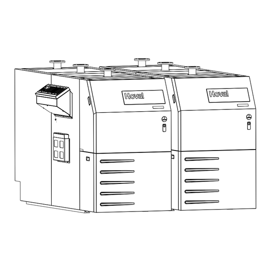
UltraOil
(320D, 400D, 500D, 600D)
®
Oil condensing double boiler
Hoval products must be installed and commissioned
only by appropriately qualified experts. These instruc-
tions are intended exclusively for the specialist. Elec-
trical installations may only be carried out by a qualified
electrician.
Subject to modifi cations
|
4 210 855 / 00 - 03/13
4 210 855 / 00 - 02/13
These instructions apply to the following
models:
30-UltraOil
®
30-UltraOil
®
30-UltraOil
®
30-UltraOil
®
The floor standing oil condensing boiler UltraOil
400D) are designed and approved for use as heat gen-
erators for hot water heating systems with a permissible
flow temperature of up to 90 ºC
483 and EN 677. They are designed for continuously
adjustable reduced output operation in heating systems.
see section technical data
1)
(320D)
118 - 320 kW
(400D)
155 - 400 kW
(500D)
188 - 500 kW
(600D)
227 - 600 kW
(320D-
®
, in accordance with EN
1)
EN
Werbung
Inhaltsverzeichnis

Verwandte Anleitungen für Hoval UltraOil 320D


Inhaltszusammenfassung für Hoval UltraOil 320D
- Seite 1 ® 30-UltraOil (600D) 227 - 600 kW ® Hoval products must be installed and commissioned The floor standing oil condensing boiler UltraOil (320D- ® only by appropriately qualified experts. These instruc- 400D) are designed and approved for use as heat gen- tions are intended exclusively for the specialist.
-
Seite 2: Inhaltsverzeichnis
TABlE OF cOnTEnTS Safety instructions Key to symbols used ................................3 Assembly Procedure way ..................................3 Technical Information Dimensions ..................................4 Space requirements ................................5 Technical data UltraOil (320D-600D) ..........................6 ® Installation Flue gas line dimensions (overpressure) ...........................8 Flue gas line dimensions (negative pressure) ........................8 Hydraulic connection ................................9 Boiler sequential switching circuit / Electrical connections / Parameters ...............9 4.6.1... -
Seite 3: Safety Instructions
• Operating instructions tions. It is imperative for the boiler commissio- 3. See separate instructions for the mounting of the flue ning to be carried out by a Hoval service gas overpressure set! engineer or a trained Hoval partner. 4. Optional: Mounting of the hydraulic pipeline connection set (common flow and return). -
Seite 4: Technical Information
TEcHnIcAl InFOrmATIOn Technical Information Dimensions UltraOil (320D-600D) ® (All dimensions in mm) UltraOil Type ® (320D) 2709 2200 1412 1492 1955 1907 106 1794 1050 2205 950 1305 (400D) 2901 2408 1412 1492 1955 1907 106 1794 1050 2205 950 1305 (500D, 600D) 3284 2708 1483 1600 2063... -
Seite 5: Space Requirements
TEcHnIcAl InFOrmATIOn Space requirements UltraOil (320D-600D) ® (All dimensions in mm) UltraOil Type ® (320D) 2709 1492 1794 (400D) 2901 1492 1794 (500D, 600D) 3284 1600 1849 Detailed dimensions and dimensions for bringing in see individual boiler UltraOil (160-300) ® Dimensions neutralisation unit see individual boiler UltraOil (160-300) -
Seite 6: Technical Data Ultraoil ® (320D-600D)
TEcHnIcAl InFOrmATIOn Technical data UltraOil (320D-600D) ® Type (320D) (400D) (500D) (600D) • Nominal output 80/60 °C • Nominal output 40/30 °C • Range of output 80/60 °C 114 - 303 147 - 380 180 - 476 215 - 568 •... -
Seite 7: Installation
InSTAllATIOn Installation b) the use of moisture-resistant chimneys which are appro- ved for flue gas temperatures of over 40 °C, connected Boiler room requirements to the oil condensing boiler in the boiler installation room Regarding the building specifications for boiler rooms and by means of approved flue gas conduits. -
Seite 8: Flue Gas Line Dimensions (Overpressure)
InSTAllATIOn Flue gas line dimensions (overpressure) Principles • Height above sea level max. 1000 m. • The first 2 m of the flue gas line are to be executed in the same dimensions as the flue gas connectors. • Combustion air: - In the case of room air-independent operation (ac- cessories optional) the air pipe must be at least the same dimension as the flue gas pipe. -
Seite 9: Hydraulic Connection
InSTAllATIOn Hydraulic connection • Ensure that the boilers are in each case connected in the Tichelmann system. • Please comply with separate installation instructions if the optional hydraulic set is used. • When using the high temperature-return, install this so that the connection socket is located on the same size (see chapter 3.1). -
Seite 10: Application Without Main Pump (System Ka100)
InSTAllATIOn 4.6.2 Application without main pump (system KA100) Boiler sequential controller circuit double boiler by TTT 0-10V SB-Y4 SB-Y4 TopTronic T TopTronic T Modul M K 1 M K 2 M K 2 M K 2 M K 3 M K 4 M K 4 Y10.1 Y10.2... - Seite 11 InSTAllATIOn Im Kessel 1, in boiler 1, in caldaia 1, en chaudière 1 Systembaustein SB-Y4 / Système modulaire SB-Y4 / Kit a elementi SB-Y4 / System unit SB-Y4 34 32 24 22 14 12 25 26 28 15 16 18 K1, K2 Relais / Relé...
- Seite 12 InSTAllATIOn Im Kessel 2, in boiler 2, in caldaia 2, en chaudière 2 Systembaustein SB-Y4 / Système modulaire SB-Y4 / Kit a elementi SB-Y4 / System unit SB-Y4 34 32 24 22 14 12 25 26 28 15 16 18 K1, K2 Relais / Relé...
- Seite 13 InSTAllATIOn = > RAMETER /PARAMETRO /PARAMETRE : SW 3.1 OLER 10, REGLER 20..., CONTROLER 20..., = > PARAMETER /PARAMETER /PARAMETRO /PARAMETRE : SW 3.1 OPTION / OPZIONE : EGULATEUR 10 REGULATORE 20..., REGULATEUR 20... REGLER 10, CONTROLER 10, REGLER 20..., CONTROLER 20..., 1) Minimalwertbegrenzung : HYDRAULIK /HYDRAULIC/ OPTION /...
-
Seite 14: Application With Main Pump (System Ka090)
InSTAllATIOn 4.6.3 Application with main pump (system KA090) Boiler sequential controller circuit double boiler by TTT 0-10V TopTronic T SB-Y4 TopTronic T SB-Y4 Modul 0-10V TopTronic T SB-Y4 TopTronic T SB-Y4 Modul M K 1 M K 2 M K 2 M K 2 M K 3 M K 4... - Seite 15 InSTAllATIOn Im Kessel 1, in boiler 1, in caldaia 1, en chaudière 1 Systembaustein SB-Y4 / Système modulaire SB-Y4 / Kit a elementi SB-Y4 / System unit SB-Y4 34 32 24 22 14 12 25 26 28 15 16 18 K1, K2 Relais / Relé...
- Seite 16 InSTAllATIOn Im Kessel 2, in boiler 2, in caldaia 2, en chaudière 2 Systembaustein SB-Y4 / Système modulaire SB-Y4 / Kit a elementi SB-Y4 / System unit SB-Y4 34 32 24 22 14 12 25 26 28 15 16 18 K1, K2 Relais / Relé...
- Seite 17 InSTAllATIOn = > METER /PARAMETRO /PARAMETRE : SW 3.1 R 10, REGLER 20..., CONTROLER 20..., = > PARAMETER /PARAMETER /PARAMETRO /PARAMETRE : SW 3.1 OPTION / OPZIONE : ULATEUR 10 REGULATORE 20..., REGULATEUR 20... REGLER 10, CONTROLER 10, REGLER 20..., CONTROLER 20..., 1) Minimalwertbegrenzung : HYDRAULIK /HYDRAULIC/ OPTION /...
-
Seite 18: Legend
InSTAllATIOn 4.6.4 Legend 4 210 855 / 00... - Seite 19 4 210 855 / 00...
- Seite 20 cOPy FOr PlAnT USEr confirmation The user (owner) of the system herewith confi rms that • he has received adequate instruction in the operating and maintenance of the installation, • received and taken note of the operating and maintenance instructions and, where applicable other documents con- cerning the heat generator and any further components.