Inhaltsverzeichnis
Werbung
Verfügbare Sprachen
Verfügbare Sprachen
Quicklinks
Instruction Manual
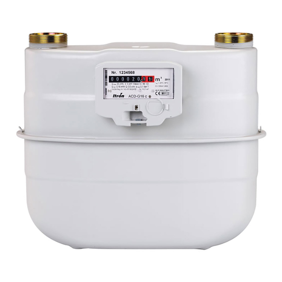
for Diaphragm Gas Meters G10 to G100
Keep this manual easily accessible for all users.
Please respect all national rules for installation,
operation and service of gas meters.
1.
Important safety instructions:
The diaphragm gas meter G10 to G100 is designed to
measure gases of the 1st, 2nd and 3rd gas family as specified in EN437 as well as various
filtered and non-corrosive gases.
If aggressive gases are to be measured, please contact Itron for specific advice or to
obtain a special version of the meter.
If there is a risk of internal or external corrosion, inspect the device regularly. If the
device is clearly affected by corrosion, put it out of use.
Before installation, the meter must be checked for possible damages during transport.
Any damage must be reported immediately to the carrier. Never install a damaged
meter.
The operating conditions indicated on the nameplate, especially maximum admissible
operation pressure and flow rate have to be respected; eventually provide appropriate
security equipment.
The device is not designed to withstand earthquakes and floods.
Repairs of the device must be performed by skilled staff or properly instructed personnel
only. Repairs must be followed by a leakage test with 1.1 x PS. The guarantee only covers
repairs done by Itron.
The maximum tightening torque of the pressure tapping point is 4 Nm, must not exceed
1 Nm for the thermowell (both connections available on request)
After connecting a pressure sensor, check the tightness of the connection.
Relieve internal pressure completely before removing the device. Ensure proper
ventilation because of possible escapes of residual gas. Cap the inlet/outlet connections.
Only screwed casing version: The inner volume (V) of the meter in litre is:
ACE10/16: V = 21,7L (not PED-relevant); G25; V = 36 L (PED); G40; V = 90 L
2.
Electrical accessories:
Remarks about using the meter in potentially hazardous areas (ATEX):
Tools with Ex-approval must be used for assembly, removal or repair in a hazardous area.
The meter must not be exposed to flames, ionising radiation or ultrasound.
The meter must be taken in account in the lightning evaluation of the complete
installation.
Pulse transmitters must be connected to intrinsic safe circuits, in accordance with EN
60079-11
Further identifications or ATEX-Certifications are not necessary.
2.1. Low frequency transmitter (standard totaliser)
As sensors, Reed switches (normally open) are used. These „passive elements" as well as
the used cables and plug connections are simple electrical equipment in conformance
with 60079-11, paragraph 5.7; they also conform to EN 60079-0. Further technical
information are written in the brochure and data sheet.
2.2. Cyble module (Cyble totaliser optional)
As an option, a communication module can be installed onto the totaliser equipped with
a Cyble target.
Further technical information and the installation procedure of the module are written in
the brochure and instruction manual of the respective Cyble modules.
3.
Transport and Storage:
Always keep the meter vertical during transport and installation. Make sure it is well fixed
on the lorry and handled without dropping. Please note that the packing material of the
meters shall be recycled.
Handle the meters with care during transport. Shock must be avoided. On receipt,
carefully examine the shipping container and the meter itself for any external damage.
Any visible damage should be reported to the carrier.
Do not remove the protection caps from the meter while in store.
Do not remove any sealing from the meter; you will invalidate the guarantee of the
product and maybe the fiscal approval of the meter.
Storage temperature range: -40° to +70°C.
4.
Installation:
The location of the meter must be easily accessible and dry. Avoid direct contact of the
meter casing with soil or concrete walls.
The device should be installed without be influenced by other components of the
installation.
The flow direction is indicated by an arrow on the body.
The piping upstream of the meter should be blown clean with dry air. Dirt and other
foreign materials can cause serious damage of the measuring unit or other parts like
gaskets.
Before installing the meter in the piping, inspect the threads of the inlet and outlet for
dirt and damage. Foreign material on the threads can cause leakage or damage to meter
connections.
For flange connections use screws whose shaft protrudes from the nut by at least one
thread pitch.
Check the alignment, the parallelism, the distance of flanges or studs. Do not use the
meter to adjust badly-fitted piping.
Werbung
Inhaltsverzeichnis

Verwandte Anleitungen für ITRON G10


Inhaltszusammenfassung für ITRON G10
- Seite 1 Please note that the packing material of the If aggressive gases are to be measured, please contact Itron for specific advice or to obtain a special version of the meter.
- Seite 2 For the connecting nut of the studs, the following maximum tightening torque apply for hard gaskets: Double pipe Single pipe Thread G1¾“A Thread G 2"A Thread G Connection (DN32) (DN40) 2¾" (DN40) G10/16 Distance [mm] 250/280 250/280/290/300 Torque 110 Nm 140 Nm 140 Nm Connection Flange DN50 Thread G2 ½"A...
- Seite 3 Si des gaz agressifs sont à mesurer, prière de contacter Itron pour des conseils spécifiques ou pour obtenir une version de compteur spéciale.
- Seite 4 : Bitubulaire Monotubulaire Raccord G1¾“ (DN32) G 2" (DN40) G 2¾" (DN40) Distance [mm] 250/280/290/300 250/280/290/300 G10/16 Couple 110 Nm 140 Nm 140 Nm Raccord bride DN50 vissé G2 ½"A bride DN50 Distance [mm]...
- Seite 5 Für weitere technische Daten sowie Montage der Module siehe Prospekt, Datenblatt bzw. Wichtige Sicherheitshinweise: Montageanleitung der jeweiligen Cyble-Modul-Variante. Die Balgengaszähler G10 bis G100 eignen sich zur Transport und Lagerung: Messung aller Gase der 1., 2. und 3. Familie entsprechend EN437 sowie allen anderen ...
- Seite 6 Druck aufbaut. Nach dem Einbau muss die Dichtheit aller Anschlüsse überprüft werden. Instandhaltung – Balgengaszähler G10 zu G100 sind wartungsfrei: Wenn der Zähler korrekt in Betrieb genommen wurde und die Arbeits-bedingungen konstant bleiben, ist keine weitere Wartung während der Betriebszeit des Zählers notwendig.
- Seite 7 Cybles disponibles. diversos gases filtrados y no corrosivos. Si es necesario medir gases agresivos, por favor, contacten con Itron para obtener instrucciones específicas o para obtener una versión Transporte y almacenaje: especial de contador.
- Seite 8 Mono tubo Rosca G1¾“A Rosca G 2¾" Conexión Rosca G 2"A (DN40) (DN32) (DN40) Distancia [mm] 250/280/290/300 250/280/290/300 G10/16 Par de apriete 110 Nm 140 Nm 140 Nm Conexión Brida DN50 Rosca G2 ½"A Brida DN50 Distancia [mm] Par de apriete...
-
Seite 9: Manuale Operativo
EN437 cosi come vari altri gas filtrati e non corrosive. Trasporto ed immagazzinamento: Se dovessero essere misurati gas corrosive, si prega di contattare Itron per specifiche analisi o Mantenere il contatore sempre in posizione verticale durante il trasporto e l’installazione. - Seite 10 Per il serraggio delle connessioni con guarnizioni dure applicare i seguenti valori di coppia: Doppio attacco Attacco singolo Filettato G1¾“A Filettato G Connessioni Filettato G 2"A (DN40) (DN32) 2¾" (DN40) G10/16 Interasse [mm] 250/280/290/300 250/280/290/300 Coppia serraggio 110 Nm 140 Nm 140 Nm Flangiato...
- Seite 11 Durante o transporte e instalação, mantenha sempre o contador/medidor na posição vertical. Por Os contadores/medidores de gás de/à diafragma G10 até G100 estão concebidos para medir gases favor tenha atenção para o facto de que a embalagem de cartão/papelão deverá ser reciclada.
- Seite 12 Para o aperto das porcas, consulte tabela seguinte, onde encontrará o torque máximo a aplicar para juntas duras: Duas tubuladuras/bocais Uma tubuladura/bocal Rosca G 2¾" Ligação Rosca G1¾“A (DN32) Rosca G 2"A (DN40) (DN40) G10/16 Distância [mm] 250/280/290/300 250/280/290/300 Torque 110 Nm 140 Nm 140 Nm Ligação Flange DN50 Rosca G2 ½"A...
-
Seite 13: Felhasználói Kézikönyv
Szállítás és tárolás: Amennyiben agresszív gáz mérése szükséges, kérjük vegye fel a kapcsolatot a helyi Itron Szállítás és tárolás során a mérő mindig függőleges helyzetben legyen. Biztosítsa a termék képviselettel! - Seite 14 A csatlakozó anyák meghúzása, a következő maximális nyomatékokkal történjen, kemény tömítés használata mellett: Kétcsonkú Egycsonkú menet G1¾“A menet G 2¾" Csatlakozás menet G 2"A (DN40) (DN32) (DN40) G10/16 Távolság [mm] 250/280 250/280/290/300 Nyomaték 110 Nm 140 Nm 140 Nm Csatlakozás karima DN50 menet G2 ½"A...
- Seite 15 Contoarele de gaz cu membrană G10 la G100 sunt proiectate să măsoare gazele din Mai multe informaţii tehnice şi de procedura de instalare a modulului sunt descrise în prima, a doua si a treia familie de gaze, in conformitate cu EN437 precum şi diferite tipuri manualul de instrucţiuni şi broşura modulelor Cyble.
- Seite 16 Pentru strângerea conexiunilor, se aplică următorul cuplu maxim de strângere pt. garniturile dure: Conexiuni duble O singura conexiune Filet G 2¾" Conexiuni Filet G1¾“A (DN32) Filet G 2"A (DN40) (DN40) G10/16 Distanta [mm] 250/280 250/280/290/300 Cuplu 110 Nm 140 Nm 140 Nm Conexiuni Flansa DN50 Filet G2 ½"A...
- Seite 17 • Meer technische informatie en de installatieprocedure van de gebruikte Cyble module Neem contact op met Itron a.u.b. voor specifiek advies of om een speciale versie vindt U in de brochure en de handleiding van de respectieve Cyblemodules. van de meter te verkrijgen wanneer er agressieve gassen gemeten moeten worden.
- Seite 18 Voor de aansluitmoer van de aansluitingen gelden volgende maximale aandraaimomenten voor harde dichtingen: Tweepijps Eenpijps Draad G 2"A Draad G 2¾" Aansluiting Draad G1¾“A (DN32) (DN40) (DN40) G10/16 Hartafstand[mm] 250/280 250/280/290/300 Aandraaimoment 110 Nm 140 Nm 140 Nm Aansluiting Flens DN50 Draad G2 ½"A...
-
Seite 19: Eu Declaration Of Conformity
EU Declaration of conformity Itron GmbH Hardeckstraße 2 D-76185 Karlsruhe declares under his sole responsibility that the product type Diaphragm Gas Meters G10 to G100 is designed and manufactured in conformity with the following directives: Until July 18 2016: 97/23/EG From July 19 2016:2014/68/EU;... -
Seite 20: Déclaration De Conformité Ue
Itron GmbH Hardeckstraße 2 D-76185 Karlsruhe Déclare sous sa seule responsabilité que le produit Compteur à membranes G10 à G100 est conçu et fabriqué en conformité avec les Directives suivantes : Jusqu´au 18.07.2016 : 97/23/CE A partir du 19.07.2016 : 2014/68/UE; Module D1 Catégorie II - DESP Cela concerne uniquement les appareils ayant une pression maximale comprise de 0,5 bar à... -
Seite 21: Eu-Konformitätserklärung
EU-Konformitätserklärung Itron GmbH Hardeckstraße 2 D-76185 Karlsruhe erklärt in alleiniger Verantwortung, dass die Produktreihen Balgengaszähler G10 bis G100 entsprechend den nachfolgenden Vorschriften konstruiert und hergestellt sind: Bis 18.07.2016: 97/23/EG Ab 19.07.2016: 2014/68/EU; Druckgeräterichtlinie (PED); Modul D1 (Kategorie II); betrifft nur zulässige Drücke PS größer 0,5 bar bis max. 1 bar (geschraubtes Gehäuse). -
Seite 22: Declaración Ue De Conformidad
Itron GmbH Hardeckstraße 2 D-76185 Karlsruhe Declara bajo su responsabilidad que el tipo de producto Contador de gas de diafragma G10 a G100 está diseñado y fabricado de conformidad con las siguientes directivas: Hasta el 18 de Julio, 2016: 97/23/CE A partir del 19 de Julio, 2016: 2014/68/UE;... -
Seite 23: Dichiarazione Di Conformità Ue
Itron GmbH Hardeckstraße 2 D-76185 Karlsruhe Dichiara sotto la propria responsabilità che il Modello di prodotto Contatore per Gas a Diaframma G10 a G100 È progettato e costruito in conformità con le seguenti Direttive: Fino al 18 Luglio 2016 97/23/CE Dal 19 Luglio 2016 2014/68/UE;... -
Seite 24: Declaração Ue De Conformidade
Hardeckstraße 2 D-76185 Karlsruhe Declara, sob sua exclusiva responsabilidade, que o produto do tipo Contador/medidor de Gás de/à Diafragma G10 até G100 está concebido e é produzido em conformidade com as seguintes diretivas/diretrizes: Até 18 de Julho de 2016: 97/23/EC A partir de 19 de Julho de 2016: 2014/68/UE;... -
Seite 25: Eu - Megfelelőségi Tanúsítvány
Itron GmbH Hardeckstraße 2 D-76185 Karlsruhe Teljes felelősségének tudatában igazolja, hogy a G10 - G100 névleges teljesítményű membrános gázmérők tervezése és gyártása az alábbi normatívák szerint történt: 2016 július 18-ig: 97/23/EG 2016 július 19-től:2014/68/EU; Pressure Equipment Directive (PED); Module D1 (Kategória II);... -
Seite 26: Declaraţia Ue De Conformitate
Itron GmbH Hardeckstraße 2 D-76185 Karlsruhe declară sub răspunderea sa exclusivă că tipul de produs Contor de gaz cu membrană, G10 până la G100, este proiectat și fabricat în conformitate cu următoarele directive: Până la 18 Iulie 2016: 97/23/EG De la 19 Iulie 2016: 2014/68/EU; Directiva pentru Echipamente sub Presiune (PED); Modulul D1 (Categoria II);... -
Seite 27: Eu-Conformiteitsverklaring
Itron GmbH Hardeckstraße 2 D-76185 Karlsruhe Verklaart dat onder zijn verantwoordelijkheid het product Balgengasmeters G10 t.e.m. G110 ontworpen is en vervaardigd wordt in overeenstemming met de volgende richtlijnen: Tot en met July 18th, 2016: 97/23/EC Na July 19th, 2016: 2014/68/EU 97/23/EG; richtlijn betreffende drukapparatuur (PED);...