Inhaltsverzeichnis
Werbung
Quicklinks
Werbung
Inhaltsverzeichnis

Verwandte Anleitungen für ROBBE Millennium 60 III PRO


Inhaltszusammenfassung für ROBBE Millennium 60 III PRO
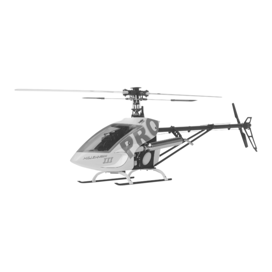
- Seite 1 III PRO No. S 2875...
-
Seite 2: Inhaltsverzeichnis
Contents Sommaire Inhaltsverzeichnis Technische Daten: Specification: Caractéristiques techniques: Hauptrotordurchmesser:ca. 1500 mm Rotor diameter: approx. 1500 mm Diamètre du rotor: approx. 1500 mm Heckrotordurchmesser: ca. 290 mm Tail rotor diameter: approx. 290 mm Diamètre du rotor arrière: Länge: ca. 1450 mm Length: approx. - Seite 3 Robbe-Schlüter Hubschrauber- renowned Robbe-Schlueter family of vous venez d’acquérir est un membre Produktfamilie. helicopter products. de la famille des hélicoptères robbe- Das Modell ist aufgrund seiner This model is of open trainer-type Schlüter. Konstruktion als Trainer in wenigen construction and is therefore easy to Ses caractéristiques de construction...
-
Seite 4: Vorwort
Robbe/Futaba servos. notice de construction font référence beziehen sich auf die Verwendung If you are using servos of different à des ensembles/servos robbe- von robbe/Futaba Servos. make you may need to make minor Futaba. La mise en place de servos Bei Einsatz von Servotypen anderen changes to these values. - Seite 5 Möglichkeit, alle Ersatzteile schnell and enclose your proof of purchase contrôle de qualité de la boîte de und unkompliziert direkt bei robbe zu (receipt) if you have a complaint or construction et joindre le ticket de beziehen. Hinweise hierzu entnehmen wish to make a claim under caisse.
-
Seite 6: Hinweise
1.Oil can - hier muß bei der - Use synthetic oil 1 la burette d’huile Montage Synthetiköl [robbe No. 5530] at this point in - à cet endroit il faut, [robbe Nr. 5530] verwendet werden. assembly. au montage, utiliser de l’huile synthétique robbe [réf. - Seite 7 Hinweise Notes Á noter Die Entstehung des Auftriebs am How the main rotor produces Génération de la portance au Hauptrotor: upthrust (lift): niveau du rotor principal: Wie bei einem Tragflügel sind die The rotor blades have a distinctive Comme l’aile d’un avion à plans fixes, Rotorblätter profiliert und unter einem profile, or airfoil section, just like a les pales de l’hélicoptère sont...
- Seite 8 Hinweise Notes Á noter Die auf der Hauptrotorwelle The swashplate serves as the Le plateau cyclique, susceptible de se angebrachte Taumelscheibe, welche mechanical means of transmitting the déplacer dans tous les sens, installé in allen Richtungen verstellbar ist, control commands from the servos to sur le rotor principal constitue le dient dabei als mechanisches the rotor.
- Seite 9 III PRO Baustufe / Stage / Stade: 1...
-
Seite 10: Montage Basismechanik
Baustufe: 1 Stage: 1 Stade: 1 1.0 Montage Basismechanik 1.0 Montage basic mechanic 1.0 Montage du mécanisme de base 1.1 Montage Tank: 1.1 Fitting the fueltank: 1.1 Montage du réservoir Tip: Tip: Zur Herstellung der Tankbohrungen We recommend that you cut the holes Un conseil: kann ein innen angesenktes in the fueltank using a length of 5 mm... - Seite 11 III PRO Baustufe / Stage / Stade: 1...
- Seite 12 Baustufe: 1 Stage: 1 Stade: 1 1.2 Montage Seitenplatten hinten 1.2 Fitting the back side-frames 1.2 Montage des plaques latérales arrière 1.3 Montage Seitenplatten vorne 1.3 Fitting the front side-frames 1.3 Montage des plaques latérales avant Hinweis: Sofern das Gasservo schon Note: if the throttle servo is already vorhanden ist, sollte es vor der available, it should be installed in the...
- Seite 13 III PRO Baustufe / Stage / Stade: 1 S3522...
- Seite 14 Baustufe: 1 Stage: 1 Stade: 1 1.4 Montage Winkelhebel und 1.4 Fitting the bellcranks and top 1.4 Montage du levier coudé et des Seitenplatten oben side-frames plaques latérales haut 1.4.1 Montage Winkelhebel 1.4.1 Fitting the bellcranks 1.4.1 Montage du levier coudé 1.4.2 Montage Seitenplatten oben 1.4.2 Fitting the top side-frames 1.4.2 Montage des plaques...
- Seite 15 III PRO Baustufe / Stage / Stade: 1...
-
Seite 16: Zusammenbau Seitenplatten
Baustufe: 1 Stage: 1 Stade: 1 1.5 Zusammenbau Seitenplatten 1.5 Fitting side-frames 1.5 Installation des plaques latérales... - Seite 17 III PRO Baustufe / Stage / Stade: 2...
-
Seite 18: Gehäuse
Baustufe: 2 Stage: 2 Stade: 2 2.0 Heckabtriebsgehäuse 2.0 Tail rotor drive housing 2.0 Carter de la transmission arrière Heckgetriebe nach Skizze montieren. Assemble the tail rotor gearbox as Monter le mécanisme du rotor arrière Nach Einbau zwischen die shown in the sketch. The correct selon les indications du schéma. - Seite 19 III PRO Baustufe / Stage / Stade: 3...
-
Seite 20: Montage Getriebestufe
Baustufe: 3 Stage: 3 Stade: 3 3.0 Montage Getriebestufe 3.0 Fitting the gearbox stage 3.0 Montage du 1er niveau du mécanisme 3.1 Montage Stirnrad Z 60: 3.1 Fitting the gear 60 T: 3.1 Montage de la couronne 60 D 3.2 Montage Freilauf 3.2 Fitting the freewheel 3.2 Montage de la roue libre Tip:... - Seite 21 III PRO Baustufe / Stage / Stade: 3...
- Seite 22 Baustufe: 3 Stage: 3 Stade: 3 3.3 Montage Hauptrotorstrang 3.3 Assembling the main rotor train 3.3 Montage du tronçon du rotor principal Mittleren Lagerbock (S4667) Install the central bearing bracket einbauen. Schrauben noch nicht (S4667), but do not tighten the screws Monter le porte-palier central (S4667).
- Seite 23 III PRO Baustufe / Stage / Stade: 3 / 4...
-
Seite 24: Montage Kufenlandegestell
Baustufe: 3 / 4 Stage: 3 / 4 Stade: 3 / 4 3.5 Montage Taumelscheibe 3.5 Fitting the swashplate 3.6 Montage du plateau cyclique Hinweis: Note: À noter: Sollte die Taumelscheibe nicht If the swashplate does not rotate Si le plateau cyclique ne glisse pas en absolut leichtgängig auf der absolutely freely on the rotor shaft, souplesse sur l’arbre du rotor, poncer... - Seite 25 III PRO Baustufe / Stage / Stade: 4...
- Seite 26 Baustufe: 4 Stage: 4 Stade: 4 4.2 Montage Servo-Halter 4.2 Fitting the servo mount 4.2 Montage des supports servo...
- Seite 27 III PRO Baustufe / Stage / Stade: 4 “G”...
-
Seite 28: Montage Kufenlandegestell
Baustufe: 4 Stage: 4 Stade: 4 4.3 Montage Kufenlandegestell 4.3 Fitting the skid landing gear 4.3 Montage du train d’atterissage Nach erfolgtem Zusammenbau des Once you have assembled the skid L’assemblage du montage du train Kufenlandegestells, wird die Einheit landing gear, fit the assembly to the d’atterissage à... - Seite 29 III PRO Baustufe / Stage / Stade: 5...
-
Seite 30: Montage Rotorkopf
Baustufe: 5 Stage: 5 Stade: 5 5.0 Montage Rotorkopf 5.0 Fitting the rotor head 5.0 Montage de la tête du rotor 5.1 Montage Pitchkompensator 5.1 Fitting the collective pitch 5.1 Montage du compensateur de compensator... - Seite 31 III PRO Baustufe / Stage / Stade: 5...
- Seite 32 Baustufe: 5 Stage: 5 Stade: 5 5.2 Montage Rotorkopf 5.2 Fitting the rotor head 5.2 Montage de la tête du rotor 5.3 Montage Blattlagerwelle 5.3 Fitting the cross axis 5.3 Montage de l’arbre des pales Hinweis: Note: À noter: Unbedingt auf die richtige Reihenfolge Be sure to keep to the sequence Observer impérativement l’ordre de bei der Montage der Axiallager...
- Seite 33 III PRO Baustufe / Stage / Stade: 5 1 mm Standard 0 mm 3 D 6 mm...
-
Seite 34: Variable Rotorkopfmischung
Baustufe: 5 Stage: 5 Stade: 5 5.4 Variable Rotorkopfmischung 5.4 Variable rotor head mixing 5.4 Mixage variable de la tête du rotor Hinweis: Note: À noter: Die Zeichnung zeigt die The drawing shows the basic set-up. Grundeinstellung. The further outwards the ball-end Le schéma présente le réglage initial Je weiter die Kugelbolzen (S3495) bolts (S3495) are fitted to the cross-... - Seite 35 III PRO Baustufe / Stage / Stade: 5...
- Seite 36 Baustufe: 5 Stage: 5 Stade: 5 5.5 Montage Mischhebel, 5.5 Fitting the mixer levers and 5.5 Montage du palonnier de Stabilisierungsstange flybar mixage, barre stabilisatrice Hinweis: Note: À noter: Stabilisierungsstange exakt mittig Set the flybar exactly central (measure Centrer parfaitement la barre ausrichten (Ausmessen).
- Seite 37 III PRO Baustufe / Stage / Stade: 5...
-
Seite 38: Montage Hauptrotorkopf
Baustufe: 5 Stage: 5 Stade: 5 5.7 Montage Hauptrotorkopf 5.7 Fitting the main rotor head 5.7 Montage de la tête du rotor principal... - Seite 39 III PRO Baustufe / Stage / Stade: 6...
-
Seite 40: Montage Heckrotorgetriebe
Baustufe: 6 Stage: 6 Stade: 6 6.0 Montage Heckrotorgetriebe 6.0 Fitting the tail rotor gearbox 6.0 Montage du mécanisme du rotor arrière 6.1 Montage Getriebegehäuse 6.1 Fitting the gearbox 6.1 Montage du carter Die Paßscheiben (S4364) dienen im You can eliminate any play between d’engrenages Bedarfsfall zur spielfreien Einstellung the bevel gears using the shim... - Seite 41 III PRO Baustufe / Stage / Stade: 6...
- Seite 42 Baustufe: 6 Stage: 6 Stade: 6 6.3 Montage Schiebehülse und 6.3 Fitting the tail rotor hub tail and 6.3 Montage du moyeu du rotor Heckrotornabe rotor sliding sleeve arrière et de la douille coulissante Unbedingt auf die richtige Reihenfolge When you install the axial bearings Observer impérativement l’ordre de bei der Montage der Axiallager (S3364) look at the correct sequence.
- Seite 43 III PRO Baustufe / Stage / Stade: 7...
-
Seite 44: Montage Heckrohr Und Starrantrieb
Baustufe: 7 Stage: 7 Stade: 7 7.0 Montage Heckrohr und 7.0 Fitting the tail boom and rigid 7.0 Montage du tube arrière et de Starrantrieb drive l’entraînement rigide 7.1 Montage Heckrohr 7.1 Fitting the tail boom 7.1 Montage de la flèche du rotor Das Heckrohr muß... - Seite 45 III PRO Baustufe / Stage / Stade: 7 S4941 S4942 S4942...
- Seite 46 Baustufe: 7 Stage: 7 Stade: 7 7.3 Zusammenbau Heckrohr, 7.3 Fitting the tail boom, vertical 7.3 Assemblage de la flèche, Höhenleitwerk, Seitenleitwerk und stabilizer, horizontal stabiliser and stabilisateur, dérive et des étais Abstützungen struts Coller les autocollants de décoration Vor der Montage des Höhen- und Apply the decor sheet transfers for du stabilisateur et de la dérive avant Seitenleitwerks die Dekorbilder...
- Seite 47 III PRO Baustufe / Stage / Stade: 8...
-
Seite 48: Montage Motoreinheit
Baustufe: 8 Stage: 8 Stade: 8 8.0 Montage Motoreinheit 8.0 Fitting the engine train 8.0 Montage du bloc moteur 8.1 Montage Lagerbock 8.1 Fitting the bearing block 8.1 Montage du support de palier Achtung: Attention: Attention: Die Inbusschrauben (S3037) erst nach Tighten the sockethead cap screws Serrer les vis six-pans creux (S3037) Montage der Motoreinheit festziehen... - Seite 49 III PRO Baustufe / Stage / Stade: 8...
-
Seite 50: Montage Motor
Baustufe: 8 Stage: 8 Stade: 8 8.3 Montage Motor 8.3 Fitting the engine 8.3 Montage du moteur Hinweis: Note: À noter: Bei Montage eines Motors mit einem If you are fitting an engine with an M8 Lorsque vous installez un moteur avec M8 Gewinde auf der Kurbelwelle, ist crankshaft thread, use the nut un filetage M 8 sur le vilebrequin, pour... - Seite 51 III PRO Baustufe / Stage / Stade: 8...
- Seite 52 Baustufe: 8 Stage: 8 Stade: 8 8.4 Einbau Motor, Motorträger und 8.4 Installing the engine, engine 8.4 Installation du moteur, support- Kupplungsglocke mount and clutch bell moteur et cloche d’embrayage Hinweis: Note: À noter: Vor Einsatz der Motoreinheit, Before attempting to run the engine Avant d’installer l’unité...
- Seite 53 III PRO Baustufe / Stage / Stade: 9...
-
Seite 54: Montage Rc-Anlage
Baustufe: 9 Stage: 9 Stade: 9 9.0 Montage RC-Anlage 9.0 Installing the receiving system 9.0 Mise en place de l’ensemble de Hinweis: components réception Die gezeigte Plazierung der RC- Note: À noter: l’implantation de l’ensemble Komponenten Akku, Empfänger und The location of the RC components de réception telle qu’elle est présentée Kreisel stellt nur einen battery, receiver and gyro shown in... - Seite 55 III PRO Baustufe / Stage / Stade: 9...
- Seite 56 Baustufe: 9 Stage: 9 Stade: 9 9.1 Programmierung und 9.1 Programming and servo set-up 9.1 Programmation et réglage des Servoeinstellung We assume the use of a radio control servos Heli- geeignete Fernsteuerungsanlage system designed for model helicopter Ensemble de radiocommande adapté Servos entsprechend use.
- Seite 57 III PRO Baustufe / Stage / Stade: 9 Ø 1 mm...
-
Seite 58: Montage
Baustufe: 9 Stage: 9 Stade: 9 Réglage du servo du pas Servoeinstellung für Roll und Nick Setting up the servos for roll and lorsque le manche de pas est déplacé Bei Rollausschlag nach rechts muß pitch-axis movements dans le sens pas maximum, il faut que sich die Taumelscheibe in Apply a roll command to the right: the les trois servos du plateau cyclique se... - Seite 59 III PRO Baustufe / Stage / Stade: 9...
- Seite 60 Baustufe: 9 Stage: 9 Stade: 9 9.5 Montage Gasservo und 9.5 Mounting the throttlo servo and 9.5 Montage du servo des gaz et Gasgestänge: throttle linkage: de la tringle des gaz Hinweis: Note: A noter: Abstand GA ausmessen und Measure dimension GA and set the Mesurer l’écart GA et régler la tringle Gestänge auf diesen Abstand pushrod to this length.
- Seite 61 III PRO Baustufe / Stage / Stade: 9...
- Seite 62 Baustufe: 9 Stage: 9 Stade: 9 9.6 Fitting the tail rotor linkage, 9.6 Montage Heckgestänge, 9.6 Montage de la tringlerie arrière, Gestängeführung und pushrod guide and tail rotor blades guide-tringle et pales du rotor Heckrotorblätter. arrière 9.6.1 Fitting the tail rotor linkage 9.6.1 Montage Heckgestänge Caution: fit the pushrod guide 9.6.1 Montage de la tringlerie...
- Seite 63 III PRO Baustufe / Stage / Stade: 9 / 10 S0039 S1036 M 3 x 10 S0030 M 3 x 8 S1005 PT 2.5 x 6.5 S0007 3.2 x 9 x 0.8 S0012 M 3 STOP S0001 3.2 x 7 x 0.5...
-
Seite 64: Montage Gebläsegehäuse
Baustufe: 9 / 10 Stage: 9 / 10 Stade: 9 / 10 9.6.2 Justage Heckrotorgestänge 9.6.2 Adjusting the tail rotor linkage 9.6.2 Ajustement de la tringle du rotor arrière - Heckgestänge montieren. - Install the tail rotor pushrod. - Servowege kontrollieren. - Check servo travels. - Seite 65 III PRO Baustufe / Stage / Stade: 10...
-
Seite 66: Kabinenhaube
Baustufe: 10 Stage: 10 Stade: 10 10.1 Kabinenhaube 10.1 Canopy 10.1 Verrière de cabine Bohrungen für die Kabine nach Drill the holes for the cabin at the Appliquer les alésages dans la cabine Markierungen anbringen. marked points. selon les repères. Haube aufsetzen und befestigen. - Seite 67 III PRO Baustufe / Stage / Stade: 11 C.G.
-
Seite 68: Hauptrotorblätter
Baustufe: 11 Stage: 11 Stade: 11 11.0 Hauptrotorblätter: 11.0 main rotor blades: 11.0 pales du rotor principal Die Hauptrotorblätter sind nicht im The main rotor blades are not Les pales du rotor principal ne sont Baukasten enthalten! Um sowohl included in the kit! pas compris dans le kit. -
Seite 69: Endkontrolle
Baustufe: 11, 12, 13 Stage: 11, 12, 13 Stade: 11, 12, 13 Eine Abweichung der 12.0 Final checks: mm, cela n’a aucune importance. Blattschwerpunkte von einem zum When all servos are at neutral the C’est l’équilibre qui est le plus anderen Blatt von nicht mehr als 5 collective pitch lever should be important et à... -
Seite 70: General Information On Programming The Radio Control System
Baustufe: 14 Stage: 14 Stade: 14 14 Allgemeines zur Program- 14 General information on program- 14.0 Généralités concernant la mierung der Fernsteuerung: ming the radio control system: programmation de l’ensemble de radiocommande Wie bereits in Baustufe 9 erläutert, As already explained in Stage 9, if a stellt die mechanisch korrekte model helicopter is to work properly it Comme expliqué... - Seite 71 Baustufe: 14 Stage: 14 Stade: 14 Erreicht werden soll, daß über den The ideal situation is that rotor speed Il faut tendre à ce que le régime reste gesamten Pitchbereich eine konstante remains constant over the whole constant sur l’ensemble de la course Drehzahl erhalten bleibt.
- Seite 72 Baustufe: 14 Stage: 14 Stade: 14 Dreht das Modell mit der Drehrichtung If the model turns around the vertical Si le modèle a tendance à tourner sur des Rotors weg, so muß der positive axis in the same direction as the main son axe vertical dans le même sens Heckrotorausgleich (REVO-UP) rotor, reduce the positive tail rotor...
- Seite 73 Fliegers zurückgreifen kann. recourse to a competent chopper par un pilote d’hélicoptère compétent. pilot. robbe Modellsport GmbH & Co. KG robbe Modellsport GmbH & Co. KG robbe Modellsport GmbH & Co. KG Technische Änderungen vorbehalten Sous réserve de modification...
-
Seite 74: Croquis
III PRO Zeichnungen und Ersatzteilliste Drawings and spare parts list Croquis et liste des pièces détachées... - Seite 75 III PRO S3522...
- Seite 76 III PRO...
- Seite 77 III PRO...
- Seite 78 III PRO...
- Seite 79 III PRO...
- Seite 80 III PRO...
- Seite 81 III PRO S4941 S4942...
- Seite 82 III PRO...
- Seite 83 III PRO...
- Seite 84 III PRO...
- Seite 85 III PRO Ersatzteile Best. Nr. Bezeichnung Liefer Best. Nr. Bezeichnung Liefer menge menge S0000 U-Scheibe 2,2x5x0,3 S1585 Paßscheibe 8x13x0,5 S0001 U-Scheibe 3,2x7x0,5 S1570 Paddelstange S0002 U-Scheibe 4,3x9x0,8 S1572 Distanzring 3x5x2,2 S0007 U-Scheibe 3,2x9x0,8 S2487 Gewindestange M4x80 S0009 Stopmutter M2,5 S2562 Tankverschluß...
- Seite 86 III PRO Ersatzteile Best. Nr. Bezeichnung Liefer Best. Nr. Bezeichnung Liefer menge menge S4334 Anlenkhebel S4826 Kupplungsglocke montiert S4348 Heckrotorgetriebegehäuse 1 Paar S4828 Kupplungsnabe S4349 Nadelrolle 3x15,81 S4831 Anlaßscheibe D15x38x10 S4350 Kugellager 3x7x3 Flansch S4833 Distanzhülse montiert D6x16,6x15 S43501 Kegelrad 17Z, Modul 0,7 S4834 Motorträgerplatte S4351...
-
Seite 87: Replacement Parts
III PRO Replacement parts Description Description supp supp S0000 Washer, 2.2 x 5 x 0.3 S1585 Shim washer, 8 x 13 x 0.5 S0001 Washer, 3.2 x 7 x 0.5 S1570 Flybar S0002 Washer, 4.3 x 9 x 0.8 S1572 Spacer ring 3 x 5 x 2.2 S0007 Washer, 3.2 x 9 x 0.8... - Seite 88 III PRO Replacement parts Description Description supp supp S4333 Outer scissor section S4826 Clutch bell, assembled S4334 Actuating lever S4828 Clutch hub S4348 Tail rotor gearbox housing 1pair S4831 Starter disc 15D x 38 x 10 S4349 Needle roller, 3 x 15.8 S4833 Spacer sleeve, assembled6D x 16.6 x 15 S4350...
-
Seite 89: Pièces De Rechange
III PRO Pièces de rechange Réf. Désignation Qté Réf. Désignation Qté livrée livrée S0000 rondelle, 2,2x 5 x 0,3 S1585 rondelle calibrée, 8x13x0,5 S0001 rondelle, 3,2x7x0,5 S1570 masselotte de barre stabilisatrice S0002 rondelle, 4,3x9x0,8 S1572 bague entretoise 3x5x2,2 S0007 rondelle, 3,2x9x0,8 S2487 tige filetée, M4x80 S0009... - Seite 90 III PRO Pièces de rechange Réf. Désignation Qté Réf. Désignation Qté livrée livrée S4334 palonnier d’asservissement S4826 cloche d’embrayage, montée S4348 carter de méc. de rotor arrière 1 paire S4828 moyen d’embrayage S4349 rouleau à aiguille, 3x15,8 S4831 rondelle de démarrage 15x38x10 S4350 roulement à...
- Seite 91 Sous réserve de d’erreur et de modification technique. Copyright robbe-Modellsport 2004 Copie et reproduction, même d’extraits, interdites sans autorisation écrite expresse de la Société robbe-Modellsport GmbH & Co. KG robbe Modellsport GmbH & Co. KG Metzloserstr. 36 Telefon: 06644 / 87-0...