Werbung
Quicklinks
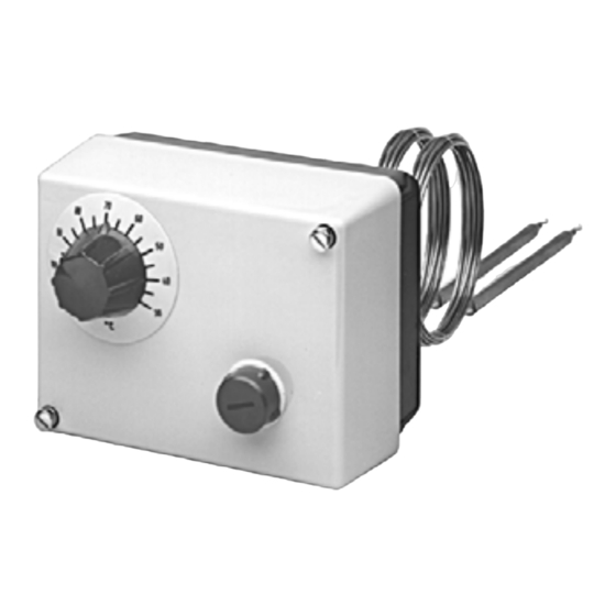
Aufbau-Thermostate, Typenreihe ATH
603021, 603026
Surface-mounting Thermostats
Series ATH 603021, 603026
Thermostat pour montage
Série ATH 603021, 603026
Betriebsanleitung
Operating Instructions
Notice de mise en service
1. Einleitung
H
Verwendung
Aufbau-Thermostate ATH überwachen oder regeln Temperaturen in
Wärmeerzeugungsanlagen und Anwendungen in der Heizungs-, Lüf-
H
tungs- und Klimatechnik.
Kennzeichnung
Ausführung nach
TR
= Temperaturregler
DIN EN 14597 als:
TW
= Temperaturwächter
STW = Sicherheits-Temperaturwächter
STB
= Sicherheits-Temperaturbegrenzer
Baumusterprüfung nach: - DIN EN 14597
- Druckgeräterichtlinie
(nur STW und STB)
Aufbau-Thermostate ATH entsprechen der DIN EN 60730 (VDE 0631).
H
Sicherheitshinweise
Knicken oder Durchtrennen der Fernleitung führt zum dauerhaften Ausfall des Gerätes.
Beim Verlegen der Fernleitung, Biegeradius 5 mm einhalten.
Beim Bruch des Messsystems kann Füllflüssigkeit austreten.
Physikalische und toxikologische Eigenschaften des Ausdehnungsmittels,
welches im Falle eines Messsystembruchs austreten kann:
Skalen-
Gefährli-
Brand- u. Explosionsgefahr
endwert
che
°C
Reaktion
Zünd-
Explosions-
temperatur
grenze
°C
Vol. %
flüssigkeitsgefüllt
< +200
nein
+355
0,6 - 8
200 +350
nein
+490
gasgefüllt
400 +500
1
Über eine Gesundheitsgefährdung bei kurzzeitiger Einwirkung und geringer Konzentration, z.B. bei
Messsystembruch, gibt es bis jetzt keine einschränkende gesundheitsbehördliche Stellungnahme.
2. Gerät identifizieren
( 1 ) Typ / max. Gehäusetemperatur / Schutzart
( 2 ) Bestellschlüssel
( 3 ) Regelbereich / Schaltleistung / Verkaufsartikel-
nummer / Fabrikationsnummer
( 4 ) Prüfzeichen / Anschlussbild
( 5 ) Fertigungswoche
( 6 ) Fertigungsjahr
3. Montage
3.1 Allgemeines
Einbaulage nach DIN 16257, NL 0...NL 90
3.2 Gehäuse öffnen
1. Deckelschrauben lösen
2. Gehäuseoberteil abnehmen
3.3 Schaltkopf befestigen
( 1 ) mit starrem Schaft
( 2 ) mit Fernleitung
( 3 ) mit Befestigungsflansch
( 4 ) mit Wandstativ
( 5 ) mit Wandbefestigung
1)
Aufbau-Doppel Thermostat = 100 mm
3.4 Schutzrohrmontage
Die Geräte dürfen nur mit passenden Schutzrohren betrieben werden.
Im Betriebsmedium Luft kein Schutzrohr einsetzen.
h Bei Ausführung mit Fernleitung, Fühler durch Klemmbügel ( 1 ) gegen Heraus-
gleiten sichern.
h Der Temperaturfühler ( 2 ) muß vollständig in das Medium eintauchen.
Fühler-Ø
Schutzrohr-Ø
Material
6 mm
08 x 0,75 mm
Messing/Edelstahl
8 mm
10 x 0,75 mm
Messing/Edelstahl
2x6 mm
15 x 0,75 mm
Messing/Edelstahl
JUMO GmbH & Co. KG
Moritz-Juchheim-Straße 1
Tel.: +49 661 6003-0
JUMO Mess- und Regelgeräte Ges.m.b.H.
Pfarrgasse 48
Tel.: +43 1 610610
JUMO Mess- und Regeltechnik AG
Laubisrütistrasse 70
Tel.: +41 44 928 24 44
JUMO Instrument Co. Ltd.
JUMO House
Phone: +44 1279 635533
JUMO Process Control, Inc.
en saillie
8 Technology Boulevard
Phone: 315-697-5866, 1-800-554-JUMO
e-mail: info@jumo.us
JUMO Régulation SAS
Actipôle Borny
Tél. : +33 3 87 37 53 00
JUMO AUTOMATION S.P.R.L. / P.G.M.B.H. / B.V.B.A
Industriestraße 18
Tél. : +32 87 59 53 00
B
Lesen Sie diese Betriebsanleitung, bevor Sie das Gerät in Betrieb nehmen.
Bitte unterstützen Sie uns, diese Betriebsanleitung zu verbessern. Für Ihre Anregungen
sind wir dankbar.
D
Telefon
H
Telefax
Sollten bei der Inbetriebnahme Schwierigkeiten auftreten, bitten wir Sie, keine unzuläs-
sigen Manipulationen oder Handlungen vorzunehmen. Der Gewährleistungsanspruch
erlischt! Bitte setzen Sie sich mit dem Lieferanten oder dem Stammhaus in Ver-
bindung.
B
Please read these Operating Instructions before commissioning the instrument.
Please assist us to improve these operating instructions, where necessary. Your com-
ments will be appreciated.
Phone
GB
H
Fax
If any difficulties should arise during starting up, please refrain from any unauthorized
manipulations or actions. The warranty will become null and void! Please contact the
B 603021.0
supplier or the head office.
B
Lisez cette notice avant de mettre en service l'appareil. Aidez-nous à améliorer cette
notice en nous faisant part de vos suggestions. Nous vous en serons reconnaissants.
Téléphone :
Télécopieur :
F
e-mail :
Service de soutien à la vente : 0892 700 733 (0,337 € /min)
H
Si vous rencontrez des difficultés lors de la mise en service, veuillez ne pas effectuer
de manipulations non autorisées. Vous pourriez compromettre votre droit à la garantie
2011-08-08/00073782
! Veuillez prendre contact avec nos services.
Introduction
Use
ATH surface-mounting thermostats monitor and control temperatures in
heat-generating plant and HVAC applications.
Marking
Version in accordance with
EN 14597 as:
Type examination to:
ATH surface-mounting and room thermostats meet EN 60730 (VDE 0631).
Safety notes
Cutting through or kinking the capillary will lead to permanent instrument failure.
When routing the long-distance line ensure a bending radius of 5 mm.
Liquid may escape in the event of a measuring system fracture.
Physical and toxicological properties of the expansion medium that may esca-
pe in the event of a measuring system fracture:
wasser-
Angaben zur Toxikologie
Scale
Hazard-
gefähr-
limit value
dend
°C
reaction
rei-
gesund-
toxisch
zend
heits-
gefährdend
1
ja
ja
nein
< +200
1
200 +350
ja
ja
nein
400 +500
nein
1
At present, there is no restrictive statement from the health authorities concerning any danger to health
over short periods and at low concentrations.
Musterbeispiel / example / exemple
( 1 )
( 2 )
( 3 )
( 4 )
( 1 )
( 3 )
( 4 )
Protection tube assembly
The appliances may only be operated with suitable protection tubes.
Do not use any protection tube in air as the operating medium air..
h For the version with long-distance line, secure the probe against dropping using
h Ensure that the temperature probe ( 2 ) completely immerges into the medium.
Probe Ø
6 mm
8 mm
2x6 mm
36039 Fulda, Germany
Fax: +49 661 6003-500
mail@jumo.net
www.jumo.net
1232 Wien, Austria
Fax: +43 1 6106140
info@jumo.at
www.jumo.at
8712 Stäfa, Switzerland
Fax: +41 44 928 24 48
info@jumo.ch
www.jumo.ch
Temple Bank, Riverway
Harlow, Essex CM20 2TT, UK
Fax: +44 1279 635262
sales@jumo.co.uk
Canastota, NY 13032, USA
Fax: 315-697-5867
Internet: www.jumo.us
7 rue des Drapiers
B.P. 45200
57075 Metz - Cedex 3, France
Fax : +33 3 87 37 89 00
info.fr@jumo.net
4700 Eupen, Belgique
Fax : +32 87 74 02 03
info@jumo.be
www.jumo.be
+49 661 6003-716
+49 661 6003-504
+49 661 6003-0
+49 661 6003-607
03 87 37 53 00
03 87 37 89 00
info.fr@jumo.net
TR
= Temperature controller
TW
= Temperature monitor
STW = Safety temperature monitor
STB
= Safety temperature limiter
- EN 14597
- Pressure Equipment Directive
(only STW and STB)
Fire and explosion hazard
hazard-
Information about toxicology
ous
ous to
waters
Ignition
Explosion lim-
irri-
dangerous
temperature
it
tant
°C
Vol. %
flüssigkeitsgefüllt
no
+355
0,6 - 8
yes
yes
no
+490
yes
yes
gas-filled
no
Instrument identification
( 1 ) Type / Max. housing temperatur / Protection
( 5 )
( 2 ) Order code
( 3 ) Control range / Contact rating / Sales number/
Serial number
( 6 )
( 4 ) Approval mark / Connection diagram
( 5 ) Week of production
( 6 ) Year of production
( 2 )
24
( 5 )
the clamping bracket ( 1 ).
Sheath Ø
Material
08 x 0.75 mm
brass/stainless steel
10 x 0.75 mm
brass/stainless steel
15 x 0.75 mm
brass/stainless steel
www.jumo.co.uk
www.jumo.fr
Introduction
Utilisation
Les thermostats pour montage en saillie ATH sont utilisés pour surveiller et régu-
ler des températures dans des installations de production de chaleur ainsi que
dans le domaine du chauffage, de la ventilation et de la climatisation.
Marquage
Exécution suivant
TR
EN 14597 comme :
TW
STW = Contrôleur de température de sécurité
STB
Examen CE de type suivant : - EN 14597
- Directive équipements sous pression
Les thermostats pour montage en saillie et d'ambiance ATH répondent aux nor-
mes EN 60730 (VDE 0631).
Nota de sécurité
Sectionnement et flambage du capillaire provoquent une panne durable.
Lors de la pose du capillaire, le rayon de courbure doit être 5 mm.
En cas de rupture du système de mesure, le liquide de remplissage peut s'échapper.
Caractéristiques physiques et toxicologiques du liquide d'expansion qui peut
s'écouler en cas de rupture du système de mesure :
Valeur fin
Réaction
Risque díexplosion et
d'échelle
dange-
d'incendie
°C
reuse
toxic
Température
to
d'inflammation
health
°C
1
no
< +200
non
+355
1
200 +350
no
non
+490
400 +500
1
Actuellement il n'existe aucune disposition restrictive à propos des risques sanitaires en cas d'émanation
momentanée ou de faible concentration, par ex. rupture du système de mesure.
Identification de l'appareil
( 1 ) Type / Température boîtier max. / Indice de protection
( 2 ) Code de commande
( 3 ) Plage de réglage / Pouvoir de coupure / Numéro d'article/
Numéro de fabrication
( 4 ) Marque d'homologation / Schéma de raccordement
( 5 ) Semaine de fabrication
( 6 ) Année de fabrication
Mounting
General
Mounting position to DIN 16257, NL 0...NL 90
Opening the housing
1. Undo the lid screws
2. Remove the case top section
Switch head fastening
( 1 ) with rigid shaft
( 2 ) with long-distance line
( 3 ) with fastening flange
( 4 ) with wall support
( 5 ) with wall fastening material
1)
Surface-mounting double thermostat = 100 mm
Montage de la gaine de protection
Les appareils ne peuvent être utilisés qu'avec des gaines de protection
adaptées.
Ne pas utiliser de gaine dans le milieu "air".
h Pour les exécutions avec capillaire, il faut s'assurer que la sonde ne coulisse pas
grâce à l'étrier de fixation ( 1 ).
h La sonde de température ( 2 ) doit être entièrement immergée dans le milieu.
Ø de la sonde
Ø de la gaine
6 mm
08 x 0,75 mm
8 mm
10 x 0,75 mm
2x6 mm
15 x 0,75 mm
= Régulateur de température.
= Contrôleur de température
= Limiteur de température de sécurité
(uniquement STW et STB)
incom-
Données toxicologique
patible à
l'eau
Limite
irritant
dangereux
toxique
d'explosion
pour la san-
Vol. %
té
Remplissage liquide
1
0,6 - 8
oui
oui
non
1
oui
oui
non
Remplissage gaz
non
Montage
Généralité
Position d'utilisation suivant DIN 16257,
NL 0...NL 90
Ouverture du boîtier
1. Dévisser les vis du couvercle
2. Retirer la partie supérieure du boîtier
Fixation du boîtier
( 1 ) avec tige rigide
( 2 ) avec capillaire
( 3 ) avec bride de fixation
( 4 ) avec Support mural
( 5 ) avec fixation murale
1)
Thermostat double pour montage
en saillie = 100 mm
Matériau
Laiton/Acier inoxydable
Laiton/Acier inoxydable
Laiton/Acier inoxydable
Werbung

Verwandte Anleitungen für JUMO ATH 603026


Inhaltszusammenfassung für JUMO ATH 603026
- Seite 1 Tél. : +33 3 87 37 53 00 Fax : +33 3 87 37 89 00 info.fr@jumo.net www.jumo.fr JUMO AUTOMATION S.P.R.L. / P.G.M.B.H. / B.V.B.A Industriestraße 18 4700 Eupen, Belgique Tél. : +32 87 59 53 00 Fax : +32 87 74 02 03 info@jumo.be...
- Seite 2 4. Einstellungen / Funktionen Settings / Functions Réglages / Fonctions TW, STW, STB: 4.1 Sollwerteinstellung Setpoint adjustment Réglage de consigne 4.2 Begrenzung Regelbereich TR Control range limiting TR Limitation de la plage de réglage TR ( 1 ) Sollwertsteller ( 1 ) abziehen Remove the set point value setter (1) Retirer le bouton de consigne ( 1 ) ( 2 )