Werbung
T0372
INSTRUCTION MANUAL • GEBRUIKSAANWIJZING • ANLEITUNG • INSTRUCTIONS DE MONTAGE
WARNING !
This R/C kit and the model you
2
29,8 dm
will build is not a toy.
LET OP !
Deze bouwdoos van een
radiobestuurd vliegtuig is geen
speelgoed.
1980 g.
ACHTUNG !
Ein Dieser Bausatz
ferngesteuertes Modell
ist kein Spielzeug.
ATTENTION !
Ce planeur R/C à assembler n'est
pas un jouet.
Werbung
Inhaltsverzeichnis

Verwandte Anleitungen für protech Stylus-E


Inhaltszusammenfassung für protech Stylus-E
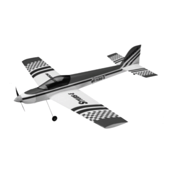
- Seite 1 T0372 INSTRUCTION MANUAL • GEBRUIKSAANWIJZING • ANLEITUNG • INSTRUCTIONS DE MONTAGE WARNING ! This R/C kit and the model you 29,8 dm will build is not a toy. LET OP ! Deze bouwdoos van een radiobestuurd vliegtuig is geen speelgoed. 1980 g.
- Seite 2 Specifi cations / Specifi caties Technische Daten / Spécifi cations Lengte: 1200 mm Length: 1200 mm Länge: 1200 mm Longueur: 1200 mm Spanwijdte: 1300 mm Wing span: 1300 mm Spannweite: 1300 mm Envergure: 1300 mm Vleugelopp.: 29,8 dm Wing area: 29,8 dm Tragfl...
- Seite 3 Tools & items / Gereedschap & benodigdheden Werkzeuge und alle Notwendigkeiten / Outils et équipements MICRO RECEIVER 5-CH FM ELECTRONIC SPEED CONTROLLER STANDARD SERVO PROTECH std servo #B305 PRO5.35 5-CH micro receiver PRO.35MPC Forward-brake Weight: 35 MHz FM 6-10 cells...
-
Seite 4: Important Safety Notes
Important Safety Notes. Be sure to read right through the instructions covering assembly and operation of your model before you at tempt to operate it for the fi rst time. You are the only person who is responsible for the safe operation of your radio-con trol led model. Young people should only be permitted to build and fl y these mod els under the instruction and su per vi sion of an adult who is aware of the hazards involved in this activity. -
Seite 5: Wichtige Sicherheitshinweise
Wichtige Sicherheitshinweise Vor dem Versuch der ersten Inbetriebnahme muß die gesamte Betriebs- und Montageanleitung sorgfältig gelesen werden. Sie allein sind verantwortlich für den sicheren Betrieb Ihres RC-Flugmodells. Bei Jugendlichen muß der Bau und Betrieb von einem Erwachsenen, der mit den Gegebenheiten und möglichen Gefahren eines RC-Flugmodells vertraut ist, verantwortlich überwacht werden. - Seite 6 Installing the ailerons / Montage van de rolroeren Montierung des Querrudern / Montage des ailerons Fig. 1 Fig. 2 Fig. 3 Steek een speldje door het mid- Fixieren Sie eine Stoßnadel im Retirez l'aileron et insérez une Insert a modelling pin through the den van de scharnieren zodat Mitte des Scharnieres so es épingle au milieu de chaque...
- Seite 7 Installing the ailerons servos / Montage van de servo's voor de rolroeren Montierung des Servos für die Querrudern / Montage des servos d'aileron Fig. 4 Fig. 5 Fig. 6 Fig. 7 Fig. 8 Remove the covering in the holes Verwijder de bespanning van de Entfernen Sie die Bespannfolie Découpez l'entoilage sur la trappe of the hatch so that the servoarms...
- Seite 8 Flächen. servo in the ailerons with an ex- te voeren. servo (PROTECH PL013.25) de tensionlead (PL013.25) of 25cm. Verbinden Sie den Servo-Kabel 25cm aux servos d'aileron. Secure the leads with some tape.
- Seite 9 Installing the control horns on the ailerons / Montage van de roerhoornen op de rolroeren Montierung von die Horner auf die Querrudern / Installation des guignols d'aileron Fig. 14 Fig. 15 Fig. 16 Fig. 17 Fig. 18 Connect the clevis to the push- Bevestig de kwiklink op de stuur- Konnektieren Sie den Gabelkopf Assemblez la commande avec...
- Seite 10 Assembling the wings / Samenstellen van de vleugel Zusammenstellen des Flugelfl ächen / Assemblage des ailes Fig.19 Fig. 20 Fig. 21 WING WOOD WOOD GLUE GLUE Fig. 22 Apply wood glue into the holes Doe een beetje houtlijm in de ga- Bringen Sie ein wenig Holz- Appliquez de la colle à...
- Seite 11 Assembling the stabilizer / Samenstellen van het hoogteroer Zusammenstellen vom Höhenruder / Assemblage du stabilisateur Fig.23 Fig. 24 Fig. 25 Fig.26 Fig. 27 Fig. 28 Remove the elevators from the Verwijder de hoogteroeren uit de Entfernen Sie die Höhenruder Retirez la gouverne de profon- stabilizer.
- Seite 12 Align the stabilizer / Uitlijnen van het hoogteroer Ausrichten vom Höhenruder / Alignement du stabilisateur Fig. 31 Fig. 32 Fig. 33 Fig. 30 Fig. 34 Fig. 35 Fig. 36 90° Fig. 38 Fig. 37 Mark a little line in the centre of Teken een lijntje in het midden van Markieren Sie die Mitte des Tracez une ligne au centre du...
- Seite 13 Installing the vertical fi n / Montage van het richtingsroer Montierung des Seitenruders / Montage de la dérive Fig. 39 Fig. 40 Fig. 41 90° Fig. 41 Fig. 42 Remove the rudder from the Verwijder het richtingsroer van Entfernen Sie das Seitenruder Séparez la gouverne de direction vertical fi...
- Seite 14 Installing the rudder & tailwheel / Montage van het richtingsroer en staartwiel Montierung des Seitenruders und Spornrad / Montage de la gouverne de direction et la roulette de queue Fig. 46 Fig. 47 Fig. 48 Fig. 49 Fig. 50 Fig. 51 Install temporarily the rudder on Installeer het richtingsroer tijdelijk Installieren Sie vorübergehend...
- Seite 15 Installing the servos / Montage van de servos Montierung den Servos / Installation des servos Fig. 52 Install the servos with their silent Installeer de servo's met hun Bringen Sie die Servos mit ihren Installez les servos avec leurs blocks. Cut off the servoarms rubberen blokjes.
- Seite 16 Connecting the pushrods / Aansluiten van de stuurstangen Anschließen vom Gestängen / Raccordement des commandes Fig. 57 Fig. 58 Fig.59 Position the pushrod on the servo Plaats de stuurstang op de servo Positionieren Sie das Gestänge Positionnez la tringle de comman- arm (check the neutral position arm (kontroleer of de roeren in een auf den Servoarm (überpruffen Sie...
- Seite 17 Assembling the landinggear / Samenstellen van het landingsgestel / Zusammenbau des Fahrgestells / Installation du train principal Fig. 63 Fig. 64 Fig.65 Slide the support of the landing- Schuif de steunen van het lan- Schieben Sie die Stützen des Insérez les 2 jambes du train dans gear in the fuselage.
- Seite 18 Installing the motor cowling and the spinner / Installeren van de motorkap en spinner / Befestigung des Motorhaubens und Spinners / Installation du capot moteur et du cône d'hélice Fig. 68 Fig. 69 Fig. 70 Place the motor cowling on the Plaats de motorkap op de romp, Platzen Sie die Motorhaube auf Installez le capot sur le fuselage,...
- Seite 19 Schwerpunkt und Ruderausschlägen / Centre de gravité et débattements des gouvernes 95 mm to 110mm 20mm 20mm Parts list / Onderdelenlijst Benötigtes / Pièces détachées T0372.1 Canopy STYLUS-E T0372.2 Wing set STYLUS-E T0372.3 Fuselage STYLUS-E T0372.4 Tail set STYLUS-E T0372.14 Motor cowling STYLUS-E T0372.15 Landing gear STYLUS-E T0372.4...
- Seite 20 All you need is inside … The PROTECH CATALOG 144 Full colour pages Ask your local R/C model shop ® is a registered trademark PROTECH P.O.-Box 60 • B-2250 Olen Tel.: +32 (0)14 25 92 83 Fax: +32 (0)14 25 92 89 info@protech.be...