
Inhaltszusammenfassung für Steffens WL
- Seite 1 Steffens INSTRUCTIONS / Bedienungsanweisung Pistonpump WL, WN / Kolbenpumpe WL, WN Installation and operating instructions / Montage- und Betriebsanleitung...
-
Seite 2: Declaration Of Conformity
We Steffens Pumpen-Fachhandel GmbH declare under our sole responsibility Wir Steffens Pumpen-Fachhandel GmbH erklären in alleiniger Verantwortung, that the products, piston pumps of the assembly type WL / WN and the dass die Produkte Kolbenpumpe der Baureihe WL / WN und die in diesen... - Seite 3 WL, WN Kolbenpumpen und Kolbenpumpen-Aggregate Installation and operating instructions Montage- und Betriebsanleitung...
-
Seite 4: Inhaltsverzeichnis
• garden sprinkling and irrigation of farmlands These instructions apply to the pump types WL, WN and the • supply of drinking water and water for sanitary purposes on FILIA, FILIUS domestic waterworks fitted with motors. -
Seite 5: Pumped Liquids
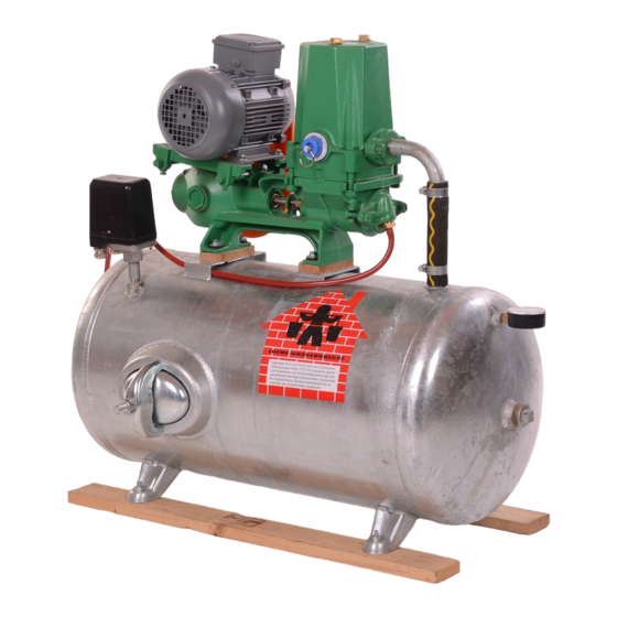
Automatic relief pressure unit serving as safety valve Connecting line Air controller with special relief valve, air controller hose and air controller valve Pressure vessel, service pressure 4 bar, fully galva- nized, type-tested Inspection hole 3.1 Pumped liquids WL/WN: Drinking water · SWL: Sea water. -
Seite 6: Technical Data
4.1 Sound pressure level 5. Align the rear belt guard wall and tighten the screws. The sound pressure level of all WL and WN piston pumps is lower than 70 dB (A). 5. Installation Before the pump is taken into operation, the... -
Seite 7: Place Of Installation
FILIA, FILIUS units 38,6 49,50 Fig. 4 Fitting of guard 7. Install the WL 4000 - 5000 belt guard in accordance with the instructions provided. 5.2 Place of installation Fig. 6 FILIA, FILIUS unit The pump should be installed in a well ventilated, dry and frost- free position. -
Seite 8: Air Control
We urgently recommend to operate pump systems with an air controller. This is the only method to ensure that the consumed air cushion of the pump air chamber and the pressure tank is Caution replenished. In case of insufficient air supply to the pump air chamber, the automatic pressure relief unit (safety valve) will be activated. -
Seite 9: Electrical Connection
In order to modify the cut-out dipstick mark. Use branded oil having a viscosity of SAE 30. pressure, follow the operating instructions of the WL 1002 - 2404: ca. 0.12 l WN 201: ca. 0.55 l pressure switch. -
Seite 10: Stuffing Box
8.2 Stuffing box The integrated stuffing box consists of a seal ring, a piston rod guide ring and high-pressure packing rings. The stuffing box should be allowed to drip slightly in order to protect the piston rod and the packing. If the box drips excessively, the stuffing box element should be carefully tightened. - Seite 11 Check the automatic pressure relief unit every six months by lifting the valve cone by the handle while the pump is running. The automatic pressure relief unit trips when the pressure in the pump air chamber is 4.0 and 6.0, Caution respectively.
-
Seite 12: Fault Finding Chart
9. Fault finding chart Before removing the terminal box cover and before any removal/dismantling of the pump, make sure that the electricity supply has been switched off. Fault Cause Remedy 1. The pump has not been a) The pump has not been primed sufficiently. Stop the pump and refill. -
Seite 13: Repair
Screw on the piston and refit the cylinder cover. Tools for piston pumps WL 2502 - 3002, WL 4000 - 5000, WN 201 - 500 Pump type Special key for Part no. key Key for a. -
Seite 14: Spare Parts
Air chamber WL2402/4 bar cpl. S5552577 Air chamber WL2402/6 bar cpl. S5552585 Air chamber SWL2402/4 bar cpl. S5552950 Air chamber WL1002/1502 machined S5530859 Flange oval R1" (WL/WN) S5540110 Flange oval R1" SWL 1002-3002 S5540129 Suction flange R11/4" WL2002/2402 S5504360 Suction flange R11/4" SWL2002/2402 S5598992... - Seite 15 Key 5/5 x 20 S5511030 O-ring D15 x 2.5 S5522716 Gasket 48/39 x 2 for pressure relief 4 + 6 bar S5598976 Stuffing box WL1002 - 2402 cpl. 96549013 Gasket kit (WL complete), 96549044, contains pos.nos 5,15,18,25, 29, 31,34, 35, 52.
- Seite 16 Air chamber SWL2502/3002 4 bar cpl. S5593486 Air chamber SWL 2502/3002 6 bar cpl. S5593494 Flange oval R1" SWL 1002-3002 S5540129 Flange oval R1" (WL/WN) S5540110 Flange oval R11/4" WL2502-4000 S5540137 Flange OV. R11/4" SWL2502-4000 S9540145 Rubber gasket 60/35 x 3...
- Seite 17 S5519294 Passageway bearing WL2502/3002, machined 96588785 Belt guard WL2502-3002 cpl. S9608408 Belt guard hood WL 2502/3002 S5539341 Oil dipstick WL2502/3002,WL1000/1500 cpl. 96590289 Gasket kit (WL complete), 96549046, contains pos nos. 5, 15, 18, 25, 27, 29, 31, 35, 52, 59.
-
Seite 18: Wl 4000-5000
Piston T-DUO D75 SWL 4/5000 S5530948 Cylinder WL 4000/5000 D75 96590278 Cylinder SWL 4000/5000 D75 S5538663 Air chamber WL 5000, 6 bar cpl. 96588794 Air chamber WL 5000, 4 bar cpl. 96588792 Air chamber WL4000, 6 bar cpl. 96588793 Air chamber WL4000, 4 bar cpl. - Seite 19 Shaft sealing ring 26/16 x 7 S5518299 Half belt guard, top S5543446 Half belt guard, bottom S5543454 Stuffing box SWL4/5000 S5530654 Gasket kit (WL complete), 96588821, contains pos. nos 5, 15, 18, 25, 27, 29, 31, 34, 35, 52, 59.
- Seite 20 V-belt pulley, WL1502-2402, 45 x 19, 2 x 10 S5598577 V-belt pulley, WL2502, 60 x 19, 2 x 10 S5501352 V-belt pulley, WL 3002/4 bar, 70 x 19, 2 x 10 S5500097 V-belt pulley, WL 3002/6 bar, 70 x 24, 2 x 10 S5500100...
-
Seite 21: Wn 201-301
Air chamber WN301/6 bar cpl. S5552755 Suction flange R11/4" WN201 bear S5504360 Flange oval R11/4" WN301 S5540137 Flange oval R1" (WL/WN) S5540110 Rubber gasket 60/35 x 3 S5519561 Rubber gasket 56/35 x 3 S5599000 V-belt pulley WN201/301 82 x 19 1 x 13... - Seite 22 Pos. Description Spare part number No./pump S5502200 Motor rail, on t. right WN201/301 Motor rail left side, WN201/301 S5502260 Pressure relief valve 4.0 bar 91043530 Pressure relief valve 6.0 bar 91043529 Bush 24/20 x 14-DWK 96590274 Rubber gasket 50/30 x 3 S5519553 Shaft sealing ring D26 x 16 x 7 96550686...
-
Seite 23: Wn 500
14.6 WN 500 Pos. Description Spare part number No./pump Piston T-DUO D82 WN500 96549011 Cylinder WN500 D82 96590279 Air chamber WN500/4 bar cpl. S5552399 Air chamber WN500/6 bar cpl. 96588796 Flange oval R11/2" WN500 S5540161 V-belt pulley WN500 89 x 24 3 x 13 S5501484 Motor base bolt D16 x 200 S5538523... -
Seite 24: Wl 1002 - 3002
15. Sectional drawings 15.1 WL 1002-2402 24 22 26 25 9 10 11 12 13 14 2 15 52, 5 52, 5 45 46 47 49,50 56 15.2 WL 2502-3002 62 12 54 63 64 42 40 63 53 24 22 26 25... - Seite 25 15.3 WL 4000-5000 21,22,23,24,25,2610 65,68,69 58 12,11 13 59 67 60 14 32 31 57,70 27 5 4 5,52 15.4 FILIA, FILIUS 38,6 49,50...
- Seite 26 15.5 WN 201-301 25,20 52,5 4 7 59 49,50 15.6 WN 500 18 29 10 12 31 67 60 48 27 52,5 Subject to alterations.
-
Seite 27: Gefahren Bei Nichtbeachtung Der Sicherheitshinweise
INHALTSVERZEICHNIS Diese Montage- und Betriebsanleitung bezieht sich auf die Pum- pentypen WL und WN, auf die Aggregate FILIA, FILIUS und die Seite Sicherheitsventile Druckstopp und Druckstopp K. Sicherheitshinweise Bei anderen, als den zum Lieferumfang gehörenden Motoren, ist Allgemeines darauf zu achten, dass die Motordaten mit den in dieser Kennzeichnung von Hinweisen Betriebsanleitung angegebenen Daten übereinstimmen. -
Seite 28: Sicherheitshinweise Für Den Betreiber/Bediener
Die in der Montage- und Betriebsanleitung 3. Verwendungszweck beschriebene Vorgehensweise zum Stillsetzen der Anlage muss unbedingt eingehalten werden. Die selbstansaugende Kolbenpumpe WL/WN findet u.a. Anwen- Unmittelbar nach Abschluss der Arbeiten müssen alle Sicher- dung heits- und Schutzeinrichtungen wieder angebracht bzw. in Funk- •... -
Seite 29: Fördermedien
Kessel EIN-AUS 4 bar 1,5 - 3,0 6 bar 3,0 - 5,0 E-Motor Riemenschutz Kolbenpumpe Bauart WL Druckstoppautomat als Sicherheitsventil Verbindungsschlauch Luftwart mit Spezial-Schnüffelventil, Luftwartschlauch und Luftwartventil Druckkessel, Betriebsüberdruck 4 bar oder 6 bar, voll- ständig verzinkt, baumustergeprüft Handloch 3.1 Fördermedien WL/WN: Trinkwasser SWL: Seewasser. -
Seite 30: Technische Daten
Abb. 4 Ansetzung von Schutzhaube 3. Motor auf Wippe aufsetzen, wobei der Wellenstumpf mit Rie- 7. Montage des Riemenschutzes für WL 4000 - 5000 erfolgt nach menscheibe durch die Riemenschutzwand gesteckt wird. der dem Riemenschutz beiliegenden Montageanweisung. Motor ausrichten und Keilriemenscheiben zum Fluchten brin-... -
Seite 31: Aufstellungsort
5.2 Aufstellungsort FILIA, FILIUS Aggregat Der Aufstellungsort sollte frostsicher und trocken sowie zur Ver- meidung von lästiger Schwitzwasserbildung belüftbar sein. Um 38,6 Wartungsarbeiten ohne Schwierigkeiten durchführen zu können, 49,50 ist gute Zugänglichkeit erforderlich. Wenn die Pumpe im Brunnenschacht montiert wird, muss eine Ölwanne vorgesehen werden. -
Seite 32: Druckleitung
Wir empfehlen dringend, Pumpenanlagen mit einem Luftwart zu betreiben. Nur so wird sicher- gestellt, dass ständig das verbrauchte Luftpols- ter im Pumpendruckwindkessel und im Druckkes- Achtung sel ergänzt wird. Mangelbelüftung im Pumpendruckwindkessel führt zum Ansprechen des Druckstoppautomaten (Sicherheitsventil). Luftergänzung bei Pumpenanlagen mit Normal- Schnüffelventil Ø... -
Seite 33: Elektrischer Anschluss
Peilstabriffelung einfüllen. Markenöle der Viskositätsstufe SAE 30 verwenden. Vor dem Entfernen des Klemmkastendeckels und WL 1002 - 2404: ca. 0,12 l WN 201: ca. 0,55 l vor jeder Demontage der Pumpe muss die Ver- WL 2502 - 3003: ca. 0,45 l WN 301: ca. -
Seite 34: Luftergänzung Im Druckwindkessel Und Druckkessel
8.6 Druckstoppautomat K Der Druckstoppautomat K ist in den Pumpendruckwindkessel ein- gebaut und schützt die Pumpe und den Druckkessel vor Über- druck. Er ist bauteilgeprüft und entspricht damit den Bestimmungen des Druckgeräte-Richtlinie RL 97/23/EG. Zum Zeichen der bestande- nen Prüfung ist auf der Druckstoppkappe das Prüfzeichen CE0045 der benannten Stelle für Druckgeräte des TÜV Nord angebracht. - Seite 35 Das Ansprechen kann vorzeitig erfolgen, wenn 1. ein zu geringes Luftpolster im Pumpendruckwindkessel vor- handen ist. Abhilfe siehe Punkt 9. 2. eine lange oder mit hohen Widerständen verlegte Druckleitung vorhanden ist. Abhilfe siehe Punkt 9. Änderungen an der Druckstoppeinstellung dürfen nur im Werk vorgenommen werden.
-
Seite 36: Störungen Und Deren Abhilfe
9. Störungen und deren Abhilfe Bevor Sie wegen einer Störung reklamieren, lesen Sie bitte das Folgende. Vielleicht können Sie den Fehler dann selbst finden. Gelingt Ihnen das nicht, rufen Sie Ihren Installateur. Störung Mögliche Ursache Abhilfe 1. Pumpe saugt nicht an, a) Pumpe ist nicht genügend angefüllt Pumpe außer Betrieb nehmen und nochmals anfüllen. -
Seite 37: Reparaturanweisung
S5130460 G 1/2 tungsmittel einsetzen und mit einem Rohr einschlagen. Kolben fest einschrauben, Zylinderdeckel wieder ansetzen. nach DIN 4810 WL 2505 - 3002, WL 4000 - 5000, WN 201 - 500 96548889 VI/2 G 1 1/4 a. Ausbau: Zylinderdeckel abschrauben, Kolben mit Rohrsteckschlüssel Werkzeug für Kolbenpumpen... -
Seite 38: Ersatzteile
S5593427 DRUCKWINDKESSEL WL2402/4BAR KPL. S5552577 DRUCKWINDKESSEL WL2402/6BAR KPL. S5552585 DRUCKWINDKESSEL SWL2402/4 BAR KPL. S5552950 DRUCKWINDKESSEL WL1002/1502 BEARB. S5530859 FLANSCH OVAL R1" (WL/WN) S5540110 FLANSCH OVAL R1" SWL 1002-3002 S5540129 SAUGFLANSCH R11/4" WL2002/2402 S5504360 SAUGFLANSCH R11/4" SWL2002/2402 S5598992 GUMMIDICHTUNG 50/30x3 S5518441... - Seite 39 96590274 S5518441 GUMMIDICHTUNG 50/30x3 DICHTUNG 50 / 30 X 3 SWL S5519553 WELLENDICHTRING 26/16x7 96550686 PAßFEDER 5/5X20 RUNDSTIRN DIN6885 S5511030 O-RING D15X2,5 DRUCKSTP.4+6BAR S5522716 GUMMIDICHTUNG 48/39x2 F.DRKSTP.4+6BAR S5598976 STOPFBUCHSE WL1002-2402 , KPL. 96549013 Dichtungskit (WL komplett) 96549044 beinhaltet Pos.Nr. [5;15;18;25;29;31;34;35;52]...
-
Seite 40: Wl 2502-3002
DRUCKWINDKESSEL WL3002/6BAR KPL. S5593524 DRUCKWINDKESSEL SWL2502/3002 4BAR KPL. S5593486 DRUCKWINDKESSEL SWL 2502/3002 6 BAR KPL. S5593494 FLANSCH OVAL R1" SWL 1002-3002 S5540129 FLANSCH OVAL R1" (WL/WN) S5540110 FLANSCH OVAL R11/4" WL2502-4000 WN301 S5540137 FLANSCH OVAL R11/4" SWL2502-4000 S9540145 GUMMIDICHTUNG 60/35x3 S5519561... - Seite 41 STÜTZRING WL2502/3002 WN201/301 KPL S5551279 ZYLINDERTEIL WL 2502/3002 96590265 ZYLINDERTEIL SWL 2502/3002 S5530441 DISTANZROHR 14/1x8 S5547213 MANILA-DICHTUNG 67/55,5 x 0,2 S5519294 DURCHGANGSLAGER WL2502/3002 96588785 RIEMENSCHUTZ WL2502-3002 KPL. S9608408 RIEMENSCHUTZHAUBE WL 2502/3002 S5539341 ÖLPEILSTAB WL2502/3002 KPL. 96590289 Dichtungskit (WL komplett) 96549046 beinhaltet Pos.Nr. [5;15;18;25;27;29;31;35;52;59]...
-
Seite 42: Wl 4000-5000
14.3 WL 4000-5000 Stück/ Pos. Benennung Ersatzteilnummer Pumpe 96548960 KOLBEN-T-DUO D75 WL4/5000 KOLBEN-T-DUO D75 SWL4/5000 S5530948 ZYLINDER WL4000/5000 D75 96590278 ZYLINDER SWL4000/5000 D75 S5538663 DRUCKWINDKESSEL WL5000/6BAR KPL. 96588794 DRUCKWINDKESSEL WL5000/4BAR KPL. 96588792 DRUCKWINDKESSEL WL4000/6BAR KPL. 96588793 DRUCKWINDKESSEL WL4000/4BAR KPL 96588791... - Seite 43 MANILA-DICHTUNG 80/68,5 x 0,2 S5519278 DURCHGANGSLAGER WL 4/5000 BEARB. 96588777 RIEMENSCHUTZ WL 4000/5000 KPL. 96590226 ÖLPEILSTAB WL4/5000 KPL. 96548996 WELLENDICHTRING 26/16 x 7 S5518299 RIEMENSCHUTZHÄLFTE WL4000/5000 S5543446 RIEMENSCHUTZHÄLFTE WL4000/5000 S5543454 STOPFBUCHSGEHÄUSE SWL4/5000 S5530654 Dichtungskit (WL komplett) 96588821 beinhaltet Pos.Nr. [5;15;18;25;27;29;31;34;35;52;59]...
-
Seite 44: Filia, Filius 14.5 Wn
SCHLAUCH 7X11X10 F.FILIA, FILIUS 96590259 GUMMIDICHTUNG 26/9,5x4 F.FILIA, FILIUS 96588812 KLEMME-SCHLAUCH 34-37 96590255 KLEMME-SCHLAUCH 37-40 S5510726 96590261 SCHLAUCH D35/25x270 SCHLAUCH D35/25x180 S5526010 96550456 BOGEN R3/4" X 60 F. AGGREG. WL 2502/3002 BOGEN R3/4" X 100 F. AGGREG.WL 1002-2402 96550457 SCHLAUCH 10/6x1500 F.LUFTWART 96590263... - Seite 45 S5552569 DRUCKWINDKESSEL WN301/6BAR KPL. S5552755 SAUGFLANSCH R11/4" WN201 S5504360 FLANSCH OVAL R11/4" WN301 S5540137 FLANSCH OVAL R1" (WL/WN) BEARB. S5540110 GUMMIDICHTUNG 60/35 x 3 WN301 S5519561 GUMMIDICHTUNG 56/35 x 3 WN201 S5599000 MOTORSCHEIBE WN201 82 x 19 1 x 13...
- Seite 46 Stück/ Pos. Benennung Ersatzteilnummer Pumpe RILLENLAGER 6203-RS 96550450 WIPPE RECHTS WN201/301 S5502200 WIPPE LINKS WN201/301 S5502260 DRUCKSTOPP 4,0 BAR 91043530 DRUCKSTOPP 6,0 BAR 91043529 WIKE-BUCHSE 24S6 / 20 x 14 96590274 GUMMIDICHTUNG 50/30 x 3 S5519553 WELLENDICHTRING 26/16 x 7 96550686 PAßFEDER 6/6 x 20 RUNDSTIRN DIN6885...
- Seite 47 14.6 WN 500 Stück/ Pos. Benennung Ersatzteilnummer Pumpe KOLBEN-T-DUO D82 WN500 96549011 ZYLINDER WN500 D82 96590279 DRUCKWINDKESSEL WN500/4BAR KPL. S5552399 DRUCKWINDKESSEL WN500/6BAR KPL. 96588796 FLANSCH OVAL R11/2" WN500 S5540161 MOTORSCHEIBE WN500 89 x 24 3 x 13 S5501484 WIPPENBOLZEN D16 x 200 S5538523 WIPPENBOLZEN D16 x 200 GEW.
-
Seite 48: Schnittzeichnungen
15. Schnittzeichnungen 15.1 WL 1002 - 2402 24 22 26 25 9 10 11 12 13 14 2 15 52, 5 52, 5 45 46 47 49,50 56 15.2 WL 2502 - 3002 62 12 54 63 64 42 40 63... -
Seite 49: Wl 4000 - 5000
15.3 WL 4000 - 5000 21,22,23,24,25,2610 65,68,69 58 12,11 13 59 67 60 14 32 31 57,70 27 5 4 5,52 15.4 FILIA, FILIUS 38,6 49,50... - Seite 50 15.5 WN 201 - 301 25,20 52,5 4 7 59 49,50 15.6 WN 500 18 29 10 12 31 67 60 48 27 52,5 Technische Änderungen vorbehalten.