Kessel Pumpfix F Comfort Einbau-, Wartungs- Und Bedienungsanleitung
Rückstaupumpanlage
Vorschau ausblenden
Andere Handbücher für Pumpfix F Comfort:
- Anleitung für einbau, bedienung und wartung (73 Seiten) ,
- Anleitung für einbau, bedienung und wartung (120 Seiten)
Inhaltsverzeichnis
Werbung
Verfügbare Sprachen
Verfügbare Sprachen
ANLEITUNG FÜR EINBAU, BEDIENUNG UND WARTUNG
KESSEL Rückstaupumpanlage
Pumpfix F Comfort
LGA
Bauart
Bauart
Landesgewerbeamt Bayern
geprüft
geprüft
und überwacht
und überwacht
LGA
Bauart
Bauart
Landesgewerbeamt Bayern
geprüft
geprüft
und überwacht
und überwacht
Installation
Inbetriebnahme
der Anlage wurde durchgeführt von Ihrem Fachbetrieb:
Name/Unterschrift
Stand 2016/05
Pumpfix F Comfort
Unterflurinstallation
Pumpfix F Comfort
Überflurinstallation
Einweisung
Datum
Produktvorteile
Für fäkalienhaltiges und
fäkalienfreies Abwasser
Rückstauverschluss und
Entwässerungspumpe
Einfacher Einbau in durchgehende
Rohrleitungen
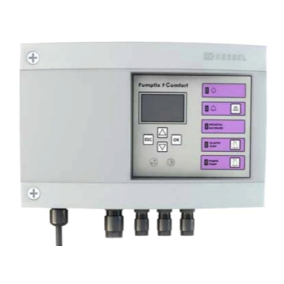
Steckerfertiges Schaltgerät mit
Display und Selbstdiagnosesystem
(SDS) mit integrierter
Batteriepufferung
Motorische Verriegelung der
Rückstauklappe
Integrierte Ablauffunktion zur
Oberflächenentwässerung
Ort
Stempel Fachbetrieb
D Seite
1
GB Page
25
F
Page
49
I
Pagina 73
NL Pagina 97
PL Strona 121
85101 Lenting
Z-53.2-388
Sach-Nr. 010-843
Werbung
Kapitel
Inhaltsverzeichnis

Verwandte Anleitungen für Kessel Pumpfix F Comfort


Inhaltszusammenfassung für Kessel Pumpfix F Comfort
- Seite 1 ANLEITUNG FÜR EINBAU, BEDIENUNG UND WARTUNG KESSEL Rückstaupumpanlage D Seite GB Page Pumpfix F Comfort Page Pagina 73 NL Pagina 97 PL Strona 121 Produktvorteile Für fäkalienhaltiges und fäkalienfreies Abwasser Rückstauverschluss und Entwässerungspumpe Einfacher Einbau in durchgehende Rohrleitungen Steckerfertiges Schaltgerät mit...
-
Seite 2: Inhaltsverzeichnis
Einleitung Produktbeschreibung, allgemein.......................3 Allgemeine Hinweise zu dieser Betriebs- und Wartungsanleitung ............4 Funktionsprinzip ..........................4 1.3.1 Funktionsprinzip Pumpfix F Comfort Unterflurinstallation ..............4 1.3.2 Funktionsprinzip Pumpfix F Comfort Überflurinstallation ..............5 Typenschild ............................5 Lieferumfang .............................6 1.5.1 Variante Pumpfix F Comfort Unterflurinstallation ................6 1.5.2 Variante Pumpfix F Comfort Überflurinstallation ................6 Sicherheit Bestimmungsgemäße Verwendung ....................7... -
Seite 3: Einleitung
Haben Sie Fragen? Wir freuen uns auf Ihre Kontaktaufnahme. Produktbeschreibung, allgemein Die KESSEL Rückstaupumpanlage Pumpfix F Comfort (im folgenden Rückstaupumpanlage benannt) ist für das Abpumpen von fäkalienfreiem und fäkalienhaltigem Abwasser vorgesehen. In den Abwasserbehälter sind die Baugruppen für die Pumpen, den optischen Sensor, die motorisch angetriebene Rückstauklappe eingebaut. -
Seite 4: Allgemeine Hinweise Zu Dieser Betriebs- Und Wartungsanleitung
VORSICHT: Warnt vor einer Gefährdung von Personen und Material. Eine Missachtung der mit diesem Symbol gekennzeichneten Hinweise kann schwere Verletzungen und Materialschäden zur Folge haben. Hinweis: Technische Hinweise, die besonders beachtet werden müssen. Funktionsprinzip 1.3.1 Funktionsprinzip Pumpfix F Comfort Unterflurinstallation Abb. [1] Rückstauebene 4 / 144 2016/05... -
Seite 5: Funktionsprinzip Pumpfix F Comfort Überflurinstallation
Einleitung 1.3.2 Funktionsprinzip Pumpfix F Comfort Überflurinstallation Abb. [2] Rückstauebene Typenschild Informationen auf dem Typenschild Bezeichnung der Anlage Materialnummer Anschlussspannung und Anschlussfrequenz Pumpfix F Comfort Hydraulische Daten xxxxx U = xxxV xxHz I = x,xA P1 = x,xkW Allgemeine Daten Q = xxm³/h... -
Seite 6: Lieferumfang
Einleitung Lieferumfang Anlage bzw. alle Lieferkomponenten auf evtl. Mängel überprüfen 1.5.1 Variante Pumpfix F Comfort Unterflurinstallation Grundkörper Aufsatzstück, mit Zulaufdeckel Verlängerungsstück (optional, max. 2 Stück) Pumpeneinheit Motorische Klappeneinheit Dichtung Kabeldurchführung Zulauf-Seite Ablauf-Seite Abb. [4] 1.5.2 Variante Pumpfix F Comfort Überflurinstallation Grundkörper... -
Seite 7: Sicherheit
Sicherheit Sicherheit Bestimmungsgemäße Verwendung Die Rückstaupumpanlage dient als Entwässerungsanlange für fäkalienhaltiges und –freies, häusliches und gewerbliches Abwasser. Personalauswahl und -qualifikation Personen, die die Rückstaupumpanlage montieren, müssen – mindestens 18 Jahre alt sein. – für die jeweiligen Tätigkeiten ausreichend geschult und qualifiziert sein. –... -
Seite 8: Gefahr Für Die Gesundheit
Sicherheit 2.4.4 Gefahr für die Gesundheit Die Rückstaupumpanlage fördert fäkalienhaltiges Abwasser, welches gesundheitsgefährdende Stoffe enthalten kann. Es ist sicherzustellen, dass kein direkter Kontakt zwischen dem Abwasser oder davon verschmutzten Anlagenteilen mit Augen, Mund oder Haut stattfindet. Bei einem direkten Kontakt die betroffene Körperstelle sofort gründlich reinigen und ggf. -
Seite 9: Montage
Montage Montage Gefahr durch giftige und gesundheitsgefährdende Dämpfe, Gase und Stoffe (z. B. Bakterien, Viren). Alle an der Rückstaupumpanlage notwendige Arbeiten ausschließlich durch Fachpersonal (Siehe 2.2) durchführen. Allgemeines zur Montage Die Rückstaupumpanlage wird entsprechend den auf einer Baustelle üblichen Bauabschnitten zu unterschiedlichen Zeitpunkten montiert und in Betrieb genommen. -
Seite 10: Einbauvorschlag „Weiße Wanne
Für einen reibungslosen Einbau und Betrieb folgendes beachten: - Ausreichend Abstand zur Wand bzw. Objekten für Wartungsarbeiten einhalten. - Beruhigungsstrecke vor und nach der Pumpfix F Comfort (min. 1 m) einhalten. - Kabelleerrohr (DN70) von der Pumpfix F Comfort zum Montageort des Schaltgeräts verlegen. -
Seite 11: Grundkörper Montieren
- Die beiden Stutzen Zulauf <56> und Ablaufseite <57> mit dem Grundkörper <1> verbinden, die Schnellverschlüsse <64> am Grundkörper ermöglichen eine rasche Montage. - Den Pumpfix F Comfort mit dem Rohrleitungssystem verbinden, Abb. [8] Abb. [9] Einbau in freiliegende Abwasserleitung Einbau in die Bodenplatte Abb. -
Seite 12: Grundkörper Waagerecht Ausrichten
Einbau in die Bodenplatte (schwarze Wanne) Bauseitige Dichtungsbahn <68> zwischen Pressdichtungsflansch <13> und Gegenflansch <47> einklemmen und mit den Schrauben <48> verschrauben. Notiz: Ist keine bauseitige Dichtungsbahn vorhanden, ist das Kessel Dichtungsset 83023 inkl. elastomerer Sperrbahn zu benutzen. Abb. [13] 12 / 144 2016/05... -
Seite 13: Einbau In Die Bodenplatte (Weiße Wanne)
Montage Einbau in die Bodenplatte (weiße Wanne) Dichtung <37> in Bodenteil <1> einlegen und auf Sitz der Dichtung achten. Anschließend Oberseite der Dichtung fetten. Verlängerungsstück mittiger Flansch <33> einschieben und in Position bringen. Abb. [14] Entlüftungsleitung anschließen (Option) Die Entlüftungsleitung muss so verlegt werden, dass sie weder den Zugang zu Wartungszwecken noch die anderen Leitungsverbindungen (Druckleitung / Kabel- Leerrohr) behindert. -
Seite 14: Kabelleerrohr Montieren
Montage 3.10 Kabelleerrohr montieren - Das Kabelleerrohr (DN70) bis zur Kabeldurchführung <41> (DN50) an den Grundkörper heranführen und montieren. Für Richtungsänderungen max. 45° Bögen verwenden. Abb. [16] 3.11 Aufsatzstück montieren Je nach Einbautiefe ist das Aufsatzstück (Einstecktiefe des Aufsatzstückes <3>) ggf. abzulängen bzw. mit Aussparungen <67>... -
Seite 15: Zulaufdeckel Montieren
Montage 3.12 Zulaufdeckel montieren Die Montage erfolgt zum Schutz vor Verunreinigungen durch z.B. Baumaterial. Dabei: - Dichtungsbereich sauber halten - Dichtung außen einfetten • Zulaufdeckel <51> in das Aufsatzstück <3> einsetzen. • Beide Deckelverschlüsse <78> schließen. Abb. [18] 2016/05 15 / 144... -
Seite 16: Wartung
Wartung Wartung Vor einem Öffnen von Gehäuseabdeckungen, Steckern und Kabeln (auch an den potentialfreien Kontakten) sind diese spannungsfrei zu machen. Arbeiten an elektrischen Bauteilen dürfen nur von Fachpersonal (Siehe 2.2) durchgeführt werden. Allgemeine Hinweise für die Wartung Bei Wartungsarbeiten darf weder auf elektrische Komponenten, Leitungsverbindungen oder Kabel gestiegen werden. - Seite 17 Wartung Inspektion-/Wartung Pumpfix F Bitte beachten Sie die Sicherheitshinweise und Unfallverhütungsvorschriften Wartungsleistungen nach EN 12056-4 u. DIN 1986 Teil 3 Objektbezeichnung Objekt Strasse PLZ, Ort Kontakt Schaltgerät nein ❏ ❏ Pumpentyp ❏ ❏ Zusatzinfos Förderhöhe: Fehlermeldung vorhanden nein ❏ ❏ LNr.
-
Seite 18: Tastenfunktion In Ordnung
Wartung LNr. Prüfung Erledigungsvermerk nein Tastenfunktion in Ordnung Messwerte ACHTUNG: Bei allen Wartungsarbeiten, Anlage vom Netz trennen! Sicherheitshinweise beachten! Nennstromangabe gemäß Typenschild auf Pumpe Gesamtzustand der Anlage Anlage geprüft und betriebsbereit Wartung Wartungs- und Servicearbeiten ohne Einschränkungen möglich Sicherungspersonal gemäß Unfallverhütungsvorschrift erforderlich (Schachteinstieg, Gaswarngerät) Funktionstest LNr. - Seite 19 ___________________________________________________________________________ verwendete Erstazteile ___________________________________________________________________________ ___________________________________________________________________________ ___________________________________________________________________________ Verbleib der ausgetauschten Ersatzteile: ❑ beim Auftraggeber ❑ beim Leistungserbringer Anlage betriebsbereit an Kunden übergeben: ..................................Werkskundendienst/Fachmann Stempel Ort, Datum .................................. Unterschrtift KESSEL AG/Werkskundendienst Name in Druckbuchstaben/Unterschrift Auftraggeber 2016/05 19 / 144...
-
Seite 20: Technische Daten
Anschlusskabel** 5 m, 3x1 mm² Erforderliche Absicherung Siehe Anleitung Schaltgerät Betriebsart S3 - 50% 5.2 Schaltgerät Pumpfix F Comfort Betriebsspannung VAC / 50Hz Leistung standby, W Leistung, W 1200 Potentialfreier Kontakt (Option), Umschaltkontakt V DC / A 42 / 0,5 Einsatztemperatur, °C... -
Seite 21: Dop/Leistungserklärung
Sicherheit und BarrierefreiheiUsafety and accessibility/securite et accessibilite 100 % recyclingfähig/ Nachhaltige Nutzung/sustainable use/utilisation durable recyclable/recyclable 1'i0\- Lenting, den 20. Mai 2016 E. Thiemt (Vorstand Technik KESSEL AG) R. Priller (Dokumentenverantwortlicher) Managing Board Responsible for Documentation Conseil d · administration Responsable de la documentation... - Seite 22 DOP/Leistungserklärung 22 / 144 2016/05...
- Seite 23 2016/05 23 / 144...
-
Seite 24: Führend In Entwässerung
Führend in Entwässerung Privater Wohnungsbau ohne Kanalanbindung 1 2 3 4 1 2 3 4 Öffentlicher Bau z.B. Krankenhaus Öffentlicher Bau z.B. Freizeitanlagen 1 2 3 4 Gewerblicher Bau z.B. Hotel Gewerblicher Bau z.B. Industriebau 2 3 5 Gewerblicher Bau z.B. - Seite 25 INSTRUCTIONS FOR INSTALLATION, OPERATION AND MAINTENANCE KESSEL Backwater Pumping Station Pumpfix F Comfort Product advantages For wastewater with and without sewage Backwater valve and draining pump Simple installation in through pipes Plug & play control unit with display Pumpfix F Comfort...
- Seite 26 How it works ............................28 1.3.1 How the Pumpfix F Comfort for underground installation works ............28 1.3.2 How the Pumpfix F Comfort for installation above ground works .............29 Type plate ............................29 Scope of delivery ..........................30 1.5.1 Variant Pumpfix F Comfort for underground installation ..............30 1.5.2...
-
Seite 27: Introduction
An optical probe is used as a level sensor. Once the corresponding level has been reached, disposal is activated by the pump against the backwater. The wastewater is pumped off via the tank of the Pumpfix F Comfort. In the event of power outage, the functional safety of the motor-driven backwater flap can be guaranteed for about 2 hours during which it is battery-operated. -
Seite 28: General Instructions On Using These Operating And Maintenance Instructions
General instructions on using these operating and maintenance instructions These operating and maintenance instructions are only complete in combination with the operating and maintenance instructions of the Pumpfix F Comfort control unit (part no. 010-846). Symbols and legends used <1>... -
Seite 29: How The Pumpfix F Comfort For Installation Above Ground Works
Introduction 1.3.2 How the Pumpfix F Comfort for installation above ground works Fig. [2] Backwater level Type plate Information on the typeplate Name of the system Material number Connection voltage and connection frequency Pumpfix F Comfort Hydraulic data xxxxx U = xxxV... -
Seite 30: Scope Of Delivery
Pump unit Motor-driven flap unit Sealing gasket Cable duct Inflow side Outlet side Fig. [4] 1.5.2 Variant Pumpfix F Comfort for installation above ground Drain body Pump unit Motor-driven flap unit Inflow side Outlet side Fig. [5] 30 / 144... -
Seite 31: Safety
Safety Safety Correct use The backwater pumping station serves as a draining system for wastewater with and without sewage, domestic and industrial wastewater. Staff selection and qualification Persons who install the backwater pumping station must – be at least 18 years old. –... -
Seite 32: Health Risks
Safety 2.4.4 Health risks The backwater pumping station pumps wastewater with sewage which can contain hazardous substances. Make sure eyes, mouth or skin do not come into direct contact with the wastewater or parts of the system soiled by it. In the case of direct contact, the part of the body affected must be washed thoroughly immediately and disinfected if necessary. -
Seite 33: Installation
Installation Installation Risk caused by toxic and hazardous vapours, gases and substances (e. g. bacteria, viruses). Always have any necessary work on the backwater pumping station done by specialist staff (see 2.2). General points related to installation The backwater pumping station is installed and put into operation at different times according to the usual construction phases on a building site. -
Seite 34: Installation Suggestion "White Tub
- Maintain a stilling section before and after the Pumpfix F Comfort (min. 1 m). - Route a cable conduit (DN70) from the Pumpfix F Comfort to where the control unit is installed. Changes of direction must be made using 45° bends only. -
Seite 35: Installing The Drain Body
- Connect the two muffs on the inflow <56> and outflow side <57> to the drain body <1>, the quick-release closures <64> on the drain body make fast installation possible. - Connect the Pumpfix F Comfort to the pipe system Fig. [8] Fig. [9]... -
Seite 36: Aligning The Drain Body Horizontally
Clamp the on-site sealing sheet <68> between the pressure sealing flange <13> and the counterflange <47> and screw together using the screws <48>. Note: If there is no on-site sealing sheet available, the Kessel sealing gasket set 83023 incl. elastomer waterproofing sheet must be used. Fig. [13] 36 / 144... -
Seite 37: Installation In The Concrete Slab (White Tub)
Installation Installation in the concrete slab (white tub) Insert the sealing gasket <37> in the base <1> and make sure the sealing gasket is in place correctly. Then grease the upper side of the sealing gasket. Push the extension section central flange <33> in and move it into position. -
Seite 38: Installing The Cable Conduit
Installation 3.10 Installing the cable conduit - Bring the cable conduit (DN70) up to the cable duct <41> (DN50) on the drain body and fit it. For changes of direction use max. 45° bends. Fig. [16] 3.11 Installing the upper section Depending on installation depth, the upper section (insertion depth of the upper section <3>) must be cut to length or given recesses <67>... -
Seite 39: Installing The Inflow Cover
Installation 3.12 Installing the inflow cover This is fitted to protect the drain from soiling through e.g. construction material. For this: - Keep the sealing area clean - Grease the outside of the sealing gasket • Insert the inflow cover <51> into the upper section <3>. •... -
Seite 40: Maintenance
Maintenance Maintenance Before housing covers, plugs and cables (including those on potential-free contacts) are opened they must be switched voltage-free. Work on electrical components may only be carried out by specialist staff (see 2.2). General maintenance information No climbing on electrical components, pipe connections or cables during maintenance work. Risk caused by toxic and hazardous vapours, gases and substances (e. - Seite 41 Maintenance Inspection/Maintenance Pumpfix F Please note the safety instructions and accident prevention regulations Maintenance work according to EN 12056-4 and DIN 1986 Part 3 Name of the building Building Street Postcode, city Contact Type Control unit yes ❏ no ❏ Pump type 1 ❏...
-
Seite 42: Functional Test
Maintenance Test Done record yes no Key function OK Measured values CAUTION: Disconnect the unit from the mains during all servicing work! Heed safety instructions! Nominal current data in accordance with the type plate on the pump Overall condition of the system System tested and ready for operation Maintenance Maintenance and service work possible without limitations... - Seite 43 ❑ at the service customer‘s System ready for operation and handed over to the customer: ..................................Factory Customer Service/Technical Expert Stamp Town, date .................................. Signature KESSEL AG/Factory Customer Service Name printed in capital letters/Signature of client 2016/05 43 / 144...
-
Seite 44: Technical Data
5 m, 3x1 mm² Required fuse protection See control unit instructions Mode of operation S3 - 50% 5.2 Control unit Pumpfix F Comfort Operating voltage VAC / 50Hz Standby capacity, W Capacity, W 1200 Potential-free contact (option), switchover contact V DC / A 42 / 0.5... -
Seite 45: Declaration Of Performance
Sicherheit und BarrierefreiheiUsafety and accessibility/securite et accessibilite 100 % recyclingfähig/ Nachhaltige Nutzung/sustainable use/utilisation durable recyclable/recyclable 1'i0\- Lenting, den 20. Mai 2016 E. Thiemt (Vorstand Technik KESSEL AG) R. Priller (Dokumentenverantwortlicher) Managing Board Responsible for Documentation Conseil d · administration Responsable de la documentation... - Seite 46 Declaration of performance 46 / 144 2016/05...
- Seite 47 2016/05 47 / 144...
-
Seite 48: Leading In Drainage
Leading in Drainage Private homes without public sewage connection 1 2 3 4 1 2 3 4 Public buildings (e.g. hospital) Public buildings (e.g. leisure facility) 1 2 3 4 Commercial buildings (e.g. hotel) Commercial buildings (e.g. industrial / manu- facturing facilities) 2 3 5 Commercial buildings... - Seite 49 INSTRUCTIONS DE MONTAGE, D’UTILISATION ET DE MAINTENANCE Clapet anti-retour avec pompe KESSEL Pumpfix F Comfort Avantages du produit Pour eaux grises et eaux-vannes Clapet anti-retour et pompe d‘épuisement Montage facile dans des canalisations sans joints Gestionnaire « prêt à brancher »...
- Seite 50 Principe de fonctionnement ......................52 1.3.1 Principe de fonctionnement du Pumpfix F Comfort à enterrer ............52 1.3.2 Principe de fonctionnement du Pumpfix F Comfort à installer hors sol ..........53 Plaque signalétique...........................53 Fournitures ............................54 1.5.1 Variante du Pumpfix F Comfort à enterrer ..................54 1.5.2...
-
Seite 51: Introduction
Chère cliente, Cher client, Nous vous félicitons de votre achat d‘un produit KESSEL. Ce produit sera certainement en mesure de répondre à toutes vos attentes. Nous vous souhaitons une mise en place sans faille et réussie. Nous tentons de maintenir un niveau de qualité aussi élevé que possible de nos produits et avons évidemment besoin de votre collaboration. -
Seite 52: Informations D'ordre Général Concernant Ces Instructions D'utilisation Et De Maintenance
Informations d‘ordre général concernant ces instructions d‘utilisation et de maintenance Ces instructions d‘utilisation et de maintenance ne sont complètes qu‘en combinaison avec les instructions d‘utilisation et de montage du gestionnaire Pumpfix F Comfort (Réf. n° 010-846). Pictogrammes et légendes utilisés <1>... -
Seite 53: Principe De Fonctionnement Du Pumpfix F Comfort À Installer Hors Sol
Introduction 1.3.2 Principe de fonctionnement du Pumpfix F Comfort à installer hors sol Ill. [2] Niveau des plus hautes eaux Plaque signalétique Information sur laplaque signalétique Désignation du poste Numéro du matériau Tension et fréquence d‘alimentation Pumpfix F Comfort Données hydrauliques... -
Seite 54: Fournitures
Unité motorisée du battant Joint d‘étanchéité Passe-câble Côté entrée Côté sortie Ill. [4] 1.5.2 Variante du Pumpfix F Comfort à installer hors sol Corps de base Unité de la pompe Unité motorisée du battant Côté entrée Côté sortie Ill. [5]... -
Seite 55: Sécurité
Sécurité Sécurité Utilisation conforme à l‘usage prévu Le clapet anti-retour avec pompe sert de système d‘assainissement des eaux-vannes, eaux grises et eaux domestiques et industrielles. Sélection et qualification du personnel Les personnes affectées au montage du clapet anti-retour avec pompe doivent –... -
Seite 56: Risque Pour La Santé
Sécurité 2.4.4 Risque pour la santé Le clapet anti-retour avec pompe refoule des eaux-vannes susceptibles de contenir des substances nuisibles à la santé. Veiller à exclure tout risque d‘un contact direct entre les eaux usées ou les éléments souillés du poste avec les yeux, la bouche ou la peau. -
Seite 57: Montage
Montage Montage Risque lié aux vapeurs, gaz et substances toxiques ou nuisible à la santé (p. ex. les bactéries, virus). Tous les travaux à effectuer sur un clapet anti-retour avec pompe demeurent réservés au domaine de compétence exclusif de personnes qualifiées (voir 2.2). Conseils de montage d‘ordre général La pose, le montage et la mise en service du clapet anti-retour avec pompe sont effectués le moment donné... -
Seite 58: Suggestion De Montage « Cuve Blanche
- prévoir suffisamment d‘espace par rapport au mur ou aux autres ouvrages pour les interventions de maintenance. - prévoir une section d‘apaisement en amont et en aval du Pumpfix F Comfort (au moins 1 m). - poser le conduit de câbles (DN de 70) du Pumpfix F Comfort jusqu‘à l‘emplacement de montage du gestionnaire. -
Seite 59: Montage Du Corps De Base
- Relier les deux manchons côté entrée <56> et côté sortie <57> avec le corps de base <1>, les fermetures rapides <64> du corps de base permettent un montage rapide. - Relier le Pumpfix F Comfort avec le système de conduites, Ill. [8] Ill. [9] Pose dans une canalisation d‘eau usée hors sol... -
Seite 60: Positionnement Horizontal Du Corps De Base
<13> et la contre-bride <47> et relier par des vis <48>. Note : à défaut d‘une bande d‘étanchéité existante sur site, utiliser le jeu de joints d’étanchéité Kessel 83023, y compris la membrane d‘étanchéité en élastomère. Ill. [13]... -
Seite 61: Pose Dans La Dalle De Fondation (Cuve Blanche)
Montage Pose dans la dalle de fondation (cuve blanche) Poser le joint d‘étanchéité <37> dans le segment inférieur <1> et veiller au logement correct du joint d‘étanchéité. Graisser ensuite la face supérieure du joint d‘étanchéité. Glisser la pièce de rallonge dans la bride médiane <33> et l‘amener à... -
Seite 62: Montage Du Conduit De Câbles
Montage 3.10 Montage du conduit de câbles - Avancer le conduit de câbles (DN de 70) jusqu‘au passe-câble <41> (DN de 50) du corps de base et le monter. Se servir de coudes d‘au plus 45° pour les changements de direction. Ill. -
Seite 63: Montage Du Couvercle D'entrée
Montage 3.12 Montage du couvercle d‘entrée Le montage s‘effectue pour protéger le poste contre les saletés, p. ex. dues aux matériaux de construction. Veiller simultanément : - à la propreté de la zone d‘étanchéité - au graissage extérieur du joint d‘étanchéité •... -
Seite 64: Maintenance
Maintenance Maintenance Débrancher impérativement les fiches d‘alimentation et câbles (y compris au niveau des contacts libres) avant d‘ouvrir les recouvrements ou caches des carters ou boîtiers. Les travaux sur les composants électriques demeurent réservés au domaine de compétence d‘électriciens qualifiés (voir 2.2). Conseils de maintenance d‘ordre général Il est interdit de monter sur les composants électriques, les raccords de tuyauterie ou les câbles lors d‘interventions de maintenance. - Seite 65 Maintenance Inspection / maintenance Pumpfix F Veuillez observer les consignes de sécurité et directives de prévention des accidents Prestations de maintenance suivant EN 12056-4 et DIN 1986, partie 3 Désignation de l‘ouvrage Ouvrage Code postal, ville Contact Modèle Gestionnaire Oui ❏ Non ❏ Type de pompe 1 ❏...
-
Seite 66: Test Fonctionnel
Maintenance Contrôle Avis d‘exécution N° oui non ad‘ordre Fonction correcte des touches Valeurs mesurées ATTENTION : Couper impérativement le courant du poste avant toute intervention de maintenance ! Respecter les consignes de sécurité ! Indication correcte du courant nominal sur la plaque signalétique de la pompe État général du poste Poste contrôlé... - Seite 67 Poste en ordre de marche remis au client : ..................................Service clientèle du fabricant / Cachet du spécialiste Date, lieu .................................. Signature de KESSEL AG / service clientèle du fabricant Nom en caractères d‘imprimerie / Signature du client 2016/05 67 / 144...
-
Seite 68: Caractéristiques Techniques
5 m, 3x1 mm² Fusible requis Voir les instructions du gestionnaire Mode de service S3 - 50 % 5.2 Gestionnaire Pumpfix F Comfort Tension de service volts C.A. / 50 Hz Puissance en veille, W Puissance, W 1200 Contact libre (en option), contact de commutation volts C.C. / A 42 / 0,5 Plage de température, °C... -
Seite 69: Déclaration De Performance
Sicherheit und BarrierefreiheiUsafety and accessibility/securite et accessibilite 100 % recyclingfähig/ Nachhaltige Nutzung/sustainable use/utilisation durable recyclable/recyclable 1'i0\- Lenting, den 20. Mai 2016 E. Thiemt (Vorstand Technik KESSEL AG) R. Priller (Dokumentenverantwortlicher) Managing Board Responsible for Documentation Conseil d · administration Responsable de la documentation... - Seite 70 Déclaration de performance 70 / 144 2016/05...
- Seite 71 2016/05 71 / 144...
- Seite 72 Leader en solution d’assainissement Construction de logements privés sans raccordement au réseau d’assainissement public 1 2 3 4 1 2 3 4 Construction de logements Construction publique, par privés sans raccordement au exemple aménagement de loisirs réseau d’assainissement public 1 2 3 4 Construction industrielle 2 3 5...
- Seite 73 ISTRUZIONI PER L’INSTALLAZIONE, L’USO E LA MANUTENZIONE Valvola di non ritorno con sistema di pompaggio KESSEL Pumpfix F Comfort Vantaggi del prodotto Per acque nere e acque grigie Chiusura per il non ritorno e pompa di drenaggio Semplice installazione nelle...
- Seite 74 Principio di funzionamento ........................76 1.3.1 Principio di funzionamento di Pumpfix F Comfort per l‘installazione sotto la pavimentazione..76 1.3.2 Principio di funzionamento di Pumpfix F Comfort per l‘installazione sopra la pavimentazione ..77 Targhetta ............................77 Fornitura ............................78 1.5.1 Variante Pumpfix F Comfort per l‘installazione sotto la pavimentazione ..........78 1.5.2...
-
Seite 75: Introduzione
Descrizione del prodotto, in generale La valvola di non ritorno con sistema di pompaggio Pumpfix F Comfort KESSEL (denominata di seguito valvola di non ritorno con sistema di pompaggio) è pensata per il pompaggio di svuotamento delle acque di scarico nere e grigie. -
Seite 76: Indicazioni Generali Sulle Presenti Istruzioni Per L'uso E La Manutenzione
Avvertenza: avvertenza tecnica che richiede particolare attenzione. Principio di funzionamento 1.3.1 Principio di funzionamento di Pumpfix F Comfort per l‘installazione sotto la pavimentazione Ill. [1] Piano di riflusso 76 / 144... -
Seite 77: Principio Di Funzionamento Di Pumpfix F Comfort Per L'installazione Sopra La Pavimentazione
Introduzione 1.3.2 Principio di funzionamento di Pumpfix F Comfort per l‘installazione sopra la pavimentazione Ill. [2] Piano di riflusso Targhetta Informazioni sullatarghetta Denominazione dell‘impianto Codice del materiale Tensione di collegamento e frequenza di Pumpfix F Comfort collegamento xxxxx Dati idraulici... -
Seite 78: Fornitura
Introduzione Fornitura Controllare l‘impianto ovvero tutti i componenti forniti alla ricerca di eventuali difetti. 1.5.1 Variante Pumpfix F Comfort per l‘installazione sotto la pavimentazione Corpo base Rialzo con coperchio d‘entrata Pezzo di prolunga (opzionale, max 2 pezzi) Unità della pompa Unità... -
Seite 79: Sicurezza
Sicurezza Sicurezza Uso conforme alla destinazione La valvola di non ritorno con sistema di pompaggio funge da impianto di drenaggio per le acque di scarico domestiche e commerciali nere e grigie. Scelta e qualifica del personale Le persone che montano la valvola di non ritorno con sistema di pompaggio devono –... -
Seite 80: Pericoli Per La Salute
Sicurezza 2.4.4 Pericoli per la salute La valvola di non ritorno con sistema di pompaggio trasporta acque di scarico contenenti sostanze fecali che possono contenere sostanze nocive per la salute. È necessario accertarsi che non avvenga alcun contatto tra le acque di scarico o le parti dell‘impianto da esse toccate e gli occhi, la bocca o la pelle. In caso di contatto diretto, lavare immediatamente con cura la parte del corpo interessata ed eventualmente disinfettare. -
Seite 81: Montaggio
Montaggio Montaggio Pericolo a causa di vapori, gas o sostanze velenose o nocive (ad esempio batteri o virus). Fare eseguire tutti i lavori necessari alla valvola di non ritorno con sistema di pompaggio a personale specializzato (vedere 2.2). Informazioni generali sul montaggio La valvola di non ritorno con sistema di pompaggio viene montata e messa in funzione in diversi momenti in base alle comuni fasi di costruzione di un cantiere. -
Seite 82: Suggerimento Di Installazione „Vasca Bianca
- Rispettare il tratto di calma a monte e a valle di Pumpfix F Comfort (minimo 1 m). - Posare il tubo vuoto per cavi (DN70) da Pumpfix F Comfort al luogo di montaggio del quadro elettrico. Eseguire i cambi di direzione solo con curve di 45°. -
Seite 83: Montaggio Del Corpo Base
- Collegare i due bocchettoni di entrata <56> e del lato di scarico <57> con il corpo base <1>, le chiusure rapide <64> sul corpo base permettono un montaggio rapido. - Collegare Pumpfix F Comfort con il sistema di tubazioni, Ill. [8] Ill. [9]... -
Seite 84: Allineamento Orizzontale Del Corpo Base
<13> e contro-flangia <47> e avvitare con le viti <48>. Nota: se non è disponibile alcun materiale impermeabilizzante del cliente deve essere usato il set di guarnizioni Kessel 83023 comprensivo di guaina impermeabilizzante in elastomero. Ill. [13]... -
Seite 85: Installazione Nel Pavimento (Vasca Bianca)
Montaggio Installazione nel pavimento (vasca bianca) Posare la guarnizione <37> nella base <1> e prestare attenzione alla sede della guarnizione. Ingrassare quindi la parte superiore della guarnizione. Innestare il pezzo di prolunga nella flangia centrale <33> e portare in posizione. Ill. -
Seite 86: Montaggio Del Tubo Vuoto Per Cavi
Montaggio 3.10 Montaggio del tubo vuoto per cavi - Condurre il tubo vuoto per cavi (DN70) fino al passante per i cavi <41> (DN50) sul corpo base e montarlo. Per i cambi di direzione impiegare delle curve di 45° al massimo. Ill. -
Seite 87: Montaggio Del Coperchio D'entrata
Montaggio 3.12 Montaggio del coperchio d‘entrata Il montaggio avviene per la protezione dalle impurità, causate ad esempio dal materiale edile. Al riguardo: - Tenere pulita l‘area della guarnizione - Ingrassare esternamente la guarnizione • Collocare il coperchio d‘entrata <51> nel rialzo <3>. •... -
Seite 88: Manutenzione
Manutenzione Manutenzione Prima dell‘apertura delle coperture dell‘alloggiamento, dei connettori e dei cavi (anche sui contatti a potenziale zero), questi devono essere privati della tensione. I lavori agli elementi elettrici devono essere eseguiti solo da personale specializzato (vedere 2.2). Avvertenze generali per la manutenzione Durante i lavori di manutenzione non è... - Seite 89 Manutenzione Ispezione / Manutenzione di Pumpfix F Prestare attenzione alle avvertenze di sicurezza e alle norme antinfortunistiche Prestazioni di manutenzione a norma EN 12056-4 e DIN 1986, parte 3 Denominazione immobile Immobile CAP, luogo Contatti Tipo Quadro elettrico sì ❏ no ❏ Tipo di pompa 1 ❏...
-
Seite 90: Test Di Funzionamento
Manutenzione N° Verifica Nota d‘esecuzione sì no Funzionamento dei tasti regolare Valori misurati ATTENZIONE: Durante tutti i lavori di manutenzione staccare l’impianto dalla rete! Rispettare le avvertenze di sicurezza! Indicazione della corrente nominale ai sensi della targhetta sulla pompa Condizioni generali dell‘impianto Impianto controllato e pronto per il funzionamento Manutenzione Lavori di manutenzione e servizio possibili senza limitazioni... - Seite 91 Impianto consegnato al cliente in condizione di prontezza per il funzionamento: ..................................Timbro del centro di assistenza dell‘azienda / dello specialista Luogo, data .................................. Firma KESSEL AG / centro di assistenza dell‘azienda Nome in stampatello / Firma del committente 2016/05 91 / 144...
-
Seite 92: Dati Tecnici
5 m, 3x1 mm² Protezione necessaria Vedere le istruzioni del quadro elettrico Tipo di funzionamento S3 – 50% 5.2 Quadro elettrico Pumpfix F Comfort Tensione di funzionamento V AC / 50 Hz Potenza stand-by, W Potenza, W 1200 Contatto a potenziale zero (opzionale), contatto di... -
Seite 93: Dop / Dichiarazione Di Prestazione
Sicherheit und BarrierefreiheiUsafety and accessibility/securite et accessibilite 100 % recyclingfähig/ Nachhaltige Nutzung/sustainable use/utilisation durable recyclable/recyclable 1'i0\- Lenting, den 20. Mai 2016 E. Thiemt (Vorstand Technik KESSEL AG) R. Priller (Dokumentenverantwortlicher) Managing Board Responsible for Documentation Conseil d · administration Responsable de la documentation... - Seite 94 DoP / Dichiarazione di prestazione 94 / 144 2016/05...
- Seite 95 2016/05 95 / 144...
- Seite 96 Leader del drenaggio Edilizia residenziale privata senza collegamento alla fogna 1 2 3 4 1 2 3 4 Edilizia pubblica per es. Ospedale Edilizia pubblica per es. Impianti ricreativi 1 2 3 4 Edilizia commerciale per es. Albergo Edilizia commerciale per es.
- Seite 97 GEBRUIKSAANWIJZING VOOR INBOUW, BEDIENING EN ONDERHOUD KESSEL terugstuwpompinstallatie Pumpfix F Comfort Productvoordelen Voor fecaliënhoudend en fecaliënvrij afvalwater Terugstroomafsluiter en afwateringspomp Eenvoudige inbouw in doorlopende buisleidingen Plug & play besturingskast met Pumpfix F Comfort zelfdiagnosesysteem (SDS) met Vloerinbouw geïntegreerde accubuffering Motorische vergrendeling van de keerklep Geïntegreerde afvoerfunctie voor...
- Seite 98 Functieprincipe Pumpfix F Comfort inbouw boven de vloer..............101 Typeplaatje............................101 Leveringsprogramma ........................102 1.5.1 Variant Pumpfix F Comfort vloerinbouw ....................102 1.5.2 Variant Pumpfix F Comfort inbouw boven de vloer ................102 Veiligheid Voorgeschreven gebruik ........................103 Personeelskeuze en -kwalificatie ......................103 Organisatorische veiligheidsmaatregelen ..................103 Gevaren die uitgaan van het product ....................103 2.4.1...
-
Seite 99: Introductie
Hebt u vragen? Wij zien ernaar uit dat u contact opneemt. Productomschrijving, algemeen De KESSEL terugstuwpompinstallatie Pumpfix F Comfort (hieronder terugstuwpompinstallatie genoemd) is beoogd voor het wegpompen van fecaliënvrij en fecaliënhoudend afvalwater. In de afvalwatertank zijn de modules voor de pompen, de optische sensor, de door een motor aangedreven terugstuwklep gemonteerd. -
Seite 100: Algemene Instructies Bij Deze Gebruiks- En Onderhoudshandleiding
Introductie Algemene instructies bij deze gebruiks- en onderhoudshandleiding Deze gebruiks- en onderhoudshandleiding is uitsluitend in combinatie met de gebruiks- en montagehandleiding van de Pumpfix F Comfort besturingskast (zaaknr. 010-846) compleet. Gebruikte symbolen en legenda <1> Verwijzing in de tekst naar een legendanummer op een afbeelding Referentie naar een afbeelding •... -
Seite 101: Functieprincipe Pumpfix F Comfort Inbouw Boven De Vloer
Introductie 1.3.2 Functieprincipe Pumpfix F Comfort inbouw boven de vloer Fig. [2] Terugstroomniveau Typeplaatje Informatie op het type-plaatje Aanduiding van de installatie Materiaalnummer Aansluitspanning en aansluitfrequentie Pumpfix F Comfort Hydraulische gegevens xxxxx U = xxxV xxHz I = x,xA P1 = x,xkW Algemene gegevens Q = xxm³/h... -
Seite 102: Leveringsprogramma
1.5.1 Variant Pumpfix F Comfort vloerinbouw Basiselement Opzetstuk, met toevoerdeksel Verlengstuk (optioneel, max. 2 stuks) Pompeenheid Motorische klepeenheid Afsluitrubber Kabeldoorvoer Toevoerzijde Afvoerzijde Fig. [4] 1.5.2 Variant Pumpfix F Comfort inbouw boven de vloer Basislichaam Pompeenheid Motorische klepeenheid Toevoerzijde Afvoerzijde Fig. [5] 102 / 144 2016/05... -
Seite 103: Veiligheid
Veiligheid Veiligheid Voorgeschreven gebruik De terugstuwpompinstallatie dient als afwateringsinstallatie voor fecaliënhoudend en fecaliënvrij, huishoudelijk en bedrijfsmatig afvalwater. Personeelskeuze en -kwalificatie Personen die de terugstuwpompinstallatie monteren, moeten – minstens 18 jaar oud zijn. – voldoende geschoold en gekwalificeerd zijn voor de betreffende activiteiten. –... -
Seite 104: Gevaar Voor De Gezondheid
Veiligheid Bij werkzaamheden bestaat het gevaar dat de atmosfeer gevaarlijk is voor de gezondheid. Op voldoende ventilatie letten en evtl. veiligheidsvoorzieningen zoals bv. gebruik maken van multigas-waarschuwingsapparaat. 2.4.4 Gevaar voor de gezondheid De terugstuwpompinstallatie transporteert fecaliënhoudend afvalwater, dat voor de gezondheid gevaarlijke stoffen kan bevatten. -
Seite 105: Montage
Montage Montage Gevaar door giftige en voor de gezondheid gevaarlijke dampen, gassen en stoffen (bv. bacteriën, virussen). Alle aan de terugstuwpompinstallatie vereiste werkzaamheden uitsluitend door geschoold personeel (zie 2.2) laten uitvoeren. Algemene zaken m.b.t. de montage De terugstuwpompinstallatie wordt conform de op een bouwplaats gebruikelijke bouwfasen op verschillende tijdstippen gemonteerd en in bedrijf genomen. -
Seite 106: Inbouwvoorstel „Witte Opvangbak
- Voldoende afstand tot de wand of objecten voor onderhoudswerkzaamheden aanhouden. - Bezinktraject vóór en achter de Pumpfix F Comfort (min. 1 m) aanhouden. - Lege kabelbuis (DN70) van de Pumpfix F Comfort naar de montageplaats van de besturingskast leggen. Richtingveranderingen uitsluitend met een bocht van 45° uitvoeren. -
Seite 107: Basiselement Monteren
- De twee moffen toevoer <56> en afvoerkant <57> met het basiselement <1> verbinden, de snelvergrendelingen <64> bij het basiselement maken een snelle montage mogelijk. - De Pumpfix F Comfort met het buisleidingssysteem verbinden, Fig. [8] Fig. [9] inbouw in vrijliggende afvalwaterleiding Inbouw in de vloerplaat Fig. -
Seite 108: Basiselement Horizontaal Uitlijnen
Op locatie aanwezige afdichtingsbaan <68> tussen persafdichtingsflens <13> en contraflens <47> klemmen en met de schroeven <48> vastdraaien. Notitie: Als er geen afdichtingsbaan op locatie aanwezig is, moet de Kessel afsluitrubberset 83023 incl. elastomeer afsluitbaan worden gebruikt. Fig. [13] 108 / 144 2016/05... -
Seite 109: Inbouw In De Vloerplaat (Witte Opvangbak)
Montage Inbouw in de vloerplaat (witte opvangbak) Afsluitrubber <37> in bodemgedeelte <1> leggen en op zitten van het afsluitrubber letten. Vervolgens bovenkant van het afsluitrubber invetten. Verlengstuk van centrale flens <33> inschuiven en in positie brengen. Fig. [14] Ontluchtingsleiding aansluiten (optie) De ontluchtingsleiding moet zodanig worden gelegd dat zij noch de toegang voor onderhoudsdoeleinden noch de andere leidingverbindingen (persleiding / lege kabelbuis) hindert. -
Seite 110: Lege Kabelbuis Monteren
Montage 3.10 Lege kabelbuis monteren - De lege kabelbuis (DN70) tot de kabeldoorvoer <41> (DN50) naar het basiselement toebrengen en monteren. Voor richtingveranderingen max. 45°-bocht gebruiken. Fig. [16] 3.11 Opzetstuk monteren Afhankelijk van de inbouwdiepte moet het opzetstuk (insteekdiepte van het opzetstuk <3>) evtl. -
Seite 111: Toevoerdeksel Monteren
Montage 3.12 Toevoerdeksel monteren Ter bescherming tegen verontreinigingen gebeurt de montage door bv. bouwmateriaal. Hierbij: - afdichtingszone schoonhouden - afsluitrubber buiten invetten • Toevoerdeksel <51> in het opzetstuk <3> zetten. • Beide dekselsluitingen <78> sluiten. Fig. [18] 2016/05 111 / 144... -
Seite 112: Onderhoud
Onderhoud Onderhoud Voordat afdekkingen van behuizingen, stekkers en kabels worden geopend (ook bij de potentiaalvrije contacten), moeten deze vrij van spanning worden gemaakt. Werkzaamheden aan elektrische componenten mogen uitsluitend door geschoold personeel (zie 2.2) worden uitgevoerd. Algemene instructies voor het onderhoud Bij onderhoudswerkzaamheden mag noch op elektrische componenten, noch op kabelverbindingen of kabels worden geklommen. - Seite 113 Onderhoud Inspectie-/onderhoud Pumpfix F Neem a.u.b. de veiligheidsinstructies en ongevalpreventievoorschriften in acht Onderhoudsprestaties conform EN 12056-4 en DIN 1986 deel 3 Objectbenaming Object Straat Postcode/plaats Contact Type Besturingskast ja ❏ nee ❏ Type pomp 1 ❏ 2 ❏ Extra informatie DN: da: Opvoerhoogte: m Storingsmelding aanwezig ja ❏...
-
Seite 114: Toetsfunctie In Orde
Onderhoud L-nr. Controle Uitvoeringsnotitie ja nee Toetsfunctie in orde meetwaarden ATTENTIE: Bij alle onderhoudswerkzaamheden de installatie loskoppelen van het net! Veiligheidsinstructies in acht nemen! Opgave nominale stroom conform typeplaatje op pomp Algehele toestand van de installatie Installatie gecontroleerd en bedrijfsklaar Onderhoud Onderhouds- en servicewerkzaamheden zonder beperkingen mogelijk Beveiligingspersoneel conform ongevalpreventievoorschrift nodig (binnengaan van schacht,... - Seite 115 Verblijfplaats van de vervangen onderdelen: ❑ bij de opdrachtgever ❑ bij de leverancier van de prestatie Installatie bedrijfsklaar overgedragen aan klant: ..................................Fabrieksklantenservice/vakman stempel Plaats, datum .................................. Handtekening KESSEL AG/fabrieksklantenservice Naam in drukletters/handtekening opdrachtgever 2016/05 115 / 144...
-
Seite 116: Technische Gegevens
Netsnoer** 5 m, 3x1 mm² Vereiste zekering Zie handleiding schakelapparaat Modus S3 - 50 % 5.2 Besturingskast Pumpfix F Comfort Bedrijfsspanning VAC / 50Hz Vermogen stand-by, W Vermogen, W 1200 Potentiaalvrij contact (optie), omschakelcontact V DC / A 42 / 0,5 Gebruikstemperatuur, °C... -
Seite 117: Dop/Vermogensverklaring
Sicherheit und BarrierefreiheiUsafety and accessibility/securite et accessibilite 100 % recyclingfähig/ Nachhaltige Nutzung/sustainable use/utilisation durable recyclable/recyclable 1'i0\- Lenting, den 20. Mai 2016 E. Thiemt (Vorstand Technik KESSEL AG) R. Priller (Dokumentenverantwortlicher) Managing Board Responsible for Documentation Conseil d · administration Responsable de la documentation... - Seite 118 DOP/vermogensverklaring 118 / 144 2016/05...
- Seite 119 2016/05 119 / 144...
-
Seite 120: Toonaangevend In Waterafvoertechniek
Toonaangevend in waterafvoertechniek Particuliere woningbouw zonder aansluiting op riool 1 2 3 4 1 2 3 4 Utiliteitsbouw bv. ziekenhuis Utiliteitsbouw bv. vrijetijdsvoorzieningen 1 2 3 4 Bedrijfsmatige bouw bv. hotel Bedrijfsmatige bouw bv. industriële bouw 2 3 5 Bedrijfsmatige bouw bv. - Seite 121 INSTRUKCJA ZABUDOWY, OBSŁUGI I KONSERWACJI Zawór zwrotny z pompą KESSEL Pumpfix F Comfort Zalety produktu Do ścieków zawierających fekalia i bez fekaliów Zawór zwrotny z pompą odwadniającą Łatwa zabudowa w ciągłym rurociągu Urządzenie sterownicze gotowe Pumpfix F Comfort do podłączenia z wyświetlaczem i Do zabudowy w płycie...
- Seite 122 Zasada działania ..........................124 1.3.1 Zasada działania urządzenia Pumpfix F Comfort do zabudowy w płycie podłogowej ......124 1.3.2 Zasada działania urządzenia Pumpfix F Comfort do zabudowy na swobodnym przewodzie kanalizacyjnym 125 Tabliczka znamionowa ........................125 Zakres dostawy ..........................126 1.5.1 Wariant Pumpfix F Comfort do zabudowy w płycie podłogowej ............126 1.5.2...
-
Seite 123: Wstęp
Pytania? Chętnie udzielimy Państwu odpowiedzi. Ogólny opis produktu Zawór zwrotny z pompą Pumpfix F Comfort firmy KESSEL (w dalszej części zwany zaworem zwrotnym z pompą) jest przeznaczony do wypompowywania ścieków zawierających fekalia i bez fekaliów. W zbiorniku ściekowym znajdują się podzespoły pomp, czujnika optycznego oraz napędzanej silnikiem klapy zwrotnej. -
Seite 124: Ogólne Informacje Dotyczącej Tej Instrukcji Obsługi I Konserwacji
Wskazówka: Wskazówki techniczne, które należy szczególnie przestrzegać. Zasada działania 1.3.1 Zasada działania urządzenia Pumpfix F Comfort do zabudowy w płycie podłogowej Rys. [1] Poziom spiętrzenia 124 / 144... -
Seite 125: Zasada Działania Urządzenia Pumpfix F Comfort Do Zabudowy Na Swobodnym Przewodzie Kanalizacyjnym
Wstęp 1.3.2 Zasada działania urządzenia Pumpfix F Comfort do zabudowy na swobodnym przewodzie kanalizacyjnym Rys. [2] Poziom spiętrzenia Tabliczka znamionowa Informacje na tabliczceznamionowej Nazwa urządzenia Numer materiału Napięcie przyłączeniowe i częstotliwość Pumpfix F Comfort przyłączeniowa xxxxx Dane hydrauliczne U = xxxV... -
Seite 126: Zakres Dostawy
Zespół pompy Zespół klapy silnikowej Uszczelka Przepust kablowy Strona dopływu Strona odpływu Rys. [4] 1.5.2 Wariant Pumpfix F Comfort do zabudowy na swobodnym przewodzie kanalizacyjnym Korpus Zespół pompy Zespół klapy silnikowej Strona dopływu Strona odpływu Rys. [5] 126 / 144... -
Seite 127: Bezpieczeństwo
Bezpieczeństwo Bezpieczeństwo Zastosowanie zgodnie z przeznaczeniem Zawór zwrotny z pompą służy jako instalacja kanalizacyjna do ścieków zawierających fekalia i bez fekaliów z gospodarstw domowych i zakładów przemysłowych. Wybór i kwalifikacje personelu Osoby dokonujące montażu zaworu zwrotnego z pompą muszą: – mieć ukończone przynajmniej 18 lat, –... -
Seite 128: Zagrożenie Dla Zdrowia
Bezpieczeństwo 2.4.4 Zagrożenie dla zdrowia Zawór zwrotny z pompą tłoczy ścieki zawierające fekalia, które mogą zawierać substancje szkodliwe dla zdrowia. Należy upewnić się, że niemożliwy jest bezpośredni kontakt ścieków lub zabrudzonych nimi elementami urządzenia z oczami, ustami lub skórą. Jeżeli dojdzie do bezpośredniego kontaktu ze ściekami lub zabrudzoną... -
Seite 129: Montaż
Montaż Montaż Niebezpieczeństwo wskutek trujących i szkodliwych oparów, gazów i pyłów (np. bakterie, wirusy). Wszelkie prace zaworze zwrotnym z pompą może wykonywać wyłącznie personel specjalistyczny (patrz 2.2). Ogólne informacje dotyczące montażu Zawór zwrotny z pompą montowany i uruchamiany jest na odpowiednich odcinkach budowy w różnym czasie. Propozycja zabudowy „czarna wanna“... -
Seite 130: Propozycja Zabudowy „Biała Wanna
- Zachować wystarczający odstęp od ściany lub obiektów, aby umożliwić konserwację. - Zachować odcinek stabilizacji przed i za urządzeniem Pumpfix F Comfort (min. 1 m). - Poprowadzić rurę ochronną na kable (DN70) od urządzenia Pumpfix F Comfort do miejsca montażu urządzenia sterującego. Zmiany kierunku wykonywać tylko przy użyciu łuków 45°. -
Seite 131: Montaż Korpusu
- Połączyć obydwa króćce od strony dopływu <56> i od strony odpływu <57> z korpusem <1>, szybkozłączki <64> na korpusie umożliwiają sprawny montaż. - Połączyć urządzenie Pumpfix F Comfort z systemem rurociągu. Rys. [8] Rys. [9] Zabudowa na swobodnym przewodzie kanalizacyjnym Zabudowa w płycie podłogowej... -
Seite 132: Ustawienie Korpusu Poziomo
Włożyć taśmę uszczelniającą klienta <68> między dociskowym kołnierzem uszczelniającym <13> i przeciwkołnierzem <47>, zacisnąć i przykręcić śrubami <48>. Uwaga: Jeżeli klient nie posiada taśmy uszczelniającej, można użyć zestawu uszczelniającego firmy Kessel nr art. 83023 zawierającego elastomerową taśmę uszczelniającą. Rys. [13] 132 / 144... -
Seite 133: Zabudowa W Płycie Podłogowej (Biała Wanna)
Montaż Zabudowa w płycie podłogowej (biała wanna) Włożyć uszczelkę <37> do części podłogowej <1>, zwracając uwagę na osadzenie uszczelki. Następnie nasmarować górną część uszczelki. Wsunąć element przedłużający środkowy kołnierz <33> i ustawić w pozycji. Rys. [14] Podłączenie przewodu odpowietrzającego (opcja) Przewód odpowietrzający należy poprowadzić... -
Seite 134: Montaż Rury Ochronnej Na Kable
Montaż 3.10 Montaż rury ochronnej na kable - Poprowadzić rurę ochronną na kable (DN70) do przepustu kablowego <41> (DN50) na korpusie i zamontować. Zmiany kierunku wykonać za pomocą łuków maks. 45°. Rys. [16] 3.11 Montaż nasady Zależnie od głębokości zabudowy należy nasadę (głębokość włożenia nasady <3>) w razie potrzeby skrócić... -
Seite 135: Montaż Pokrywy Dopływowej
Montaż 3.12 Montaż pokrywy dopływowej Montaż wykonywany jest w celu ochrony przed zabrudzeniami np. materiałem budowlanym. Należy przy tym; - Zachować czystość obszaru uszczelnienia. - Nasmarować uszczelkę z zewnątrz. • Włożyć pokrywę dopływową <51> do nasady k <3>. • Zamknąć obydwa zamknięcia pokrywy <78>. Rys. -
Seite 136: Konserwacja
Konserwacja Konserwacja Przed otwarciem pokryw, wtyczek i kabli (również na stykach bezpotencjałowych) należy odłączyć zasilanie. Prace wykonywane przy podzespołach elektrycznych może wykonywać tylko personel specjalistyczny (patrz 2.2). Ogólne informacje dotyczące konserwacji Podczas prac konserwacyjnych nie wolno wspinać się na komponenty elektryczne, połączenia przewodów lub kable. - Seite 137 Konserwacja Inspekcja/konserwacja urządzenia Pumpfix F Przestrzegać wskazówek bezpieczeństwa i przepisów bezpieczeństwa pracy Konserwacja wg EN 12056-4 i DIN 1986 część 3 Nazwa obiektu Obiekt Ulica Kod pocztowy, miejscowość Kontakt Urządzenie sterujące tak ❏ nie ❏ Typ pompy 1 ❏ 2 ❏ Informacje dodatkowe DN: da: Wysokość...
- Seite 138 Konserwacja Bież. Kontrola Wykonana Jeżeli obecna jest bateria/akumulator do eksploatacji niezależnie od sieci - komunikat o błędzie prawidłowy Wskaźniki LED na urządzeniu sterującym prawidłowe Funkcje przycisków poprawne Wartości zmierzone UWAGA: Podczas wszystkich prac konserwacyjnych należy instalację odłączyć od sieci! Przestrzegać wskazówek bezpieczeństwa! Wartość...
- Seite 139 ❑ Zleceniodawca ❑ Usługodawca Urządzenie przekazane klientowi w stanie gotowym do użytku: ..................................Pieczątka zakład serwisowy / specjalista Miejscowość/data .................................. Podpis KESSEL AG / zakład serwisowy Imię i nazwisko drukowanymi literami / podpis zleceniodawcy 2016/05 139 / 144...
-
Seite 140: Dane Techniczne
Wymagane zabezpieczenie Patrz instrukcja urządzenia sterującego Rodzaj trybu S3 - 50% 5.2 Urządzenie sterujące Pumpfix F Comfort Napięcie robocze VAC / 50 Hz Moc w stanie stan gotowości, W Moc, W 1200 Zestyk bezpotencjałowy (opcja), styk przełączny V DC / A 42 / 0,5 Temperatura użytkowania... -
Seite 141: Dop / Deklaracja Właściwości Użytkowych
Sicherheit und BarrierefreiheiUsafety and accessibility/securite et accessibilite 100 % recyclingfähig/ Nachhaltige Nutzung/sustainable use/utilisation durable recyclable/recyclable 1'i0\- Lenting, den 20. Mai 2016 E. Thiemt (Vorstand Technik KESSEL AG) R. Priller (Dokumentenverantwortlicher) Managing Board Responsible for Documentation Conseil d · administration Responsable de la documentation... - Seite 142 DOP / Deklaracja właściwości użytkowych 142 / 144 2016/05...
- Seite 143 2016/05 143 / 144...
- Seite 144 Rückseite_PL_Layout 1 25.06.13 16:13 Seite 1 Wiodący producent systemów odwadniania Budownictwo mieszkaniowe bez podłączenia do kanalizacji 1 2 3 4 5 1 2 3 4 5 Budynki użyteczności Budowle ogólnodostępne publicznej, np. szpitale np. obiekty rekreacyjne Działalność gospodarcza np. hotele Budownictwo przemysłowe 2 3 5...