Werbung
Quicklinks
Montageanleitung
Instructions de Montage
Mounting Instructions
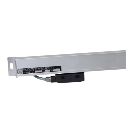
LS 500
für Positionsanzeige
pour l'Affichage de positions
for Digital Readout
Heidenhain
DR. JOHANNES
Feinmechanik,Optik und Elektronik • Präzisionsteilungen
Postfach
1260 • D-8225 Traunreut
Telex:
05 6831 • Telegrammanschritt:
DR. JOHANNES
HEIDENHAIN
OR: JOHANNES
HEIDENHAIN
5041
HEIDENHAIN
Teteton:
(0 86 69) 31-1
DIADIJR Traunreut
G
LS 500
LS 500
Werbung

Verwandte Anleitungen für HEIDENHAIN LS 500


Inhaltszusammenfassung für HEIDENHAIN LS 500
- Seite 1 Montageanleitung Instructions de Montage Mounting Instructions LS 500 für Positionsanzeige pour l'Affichage de positions for Digital Readout Heidenhain 5041 DR. JOHANNES HEIDENHAIN Feinmechanik,Optik und Elektronik • Präzisionsteilungen Postfach 1260 • D-8225 Traunreut Teteton: (0 86 69) 31-1 Telex: 05 6831 • Telegrammanschritt: DIADIJR Traunreut DR.
- Seite 2 Blockplan Montagehinweise Suite des opérations Mounting instructions Technical specifications de montage Technische Daten Schéma 4.1. Measuring system LS500 4.1. Meßsystem LS 500 4.2. Steck&rbelegung6-polig Instructions de montage 4.2. Connector (6 poles) 4.3. Steckerbelegung 9-polig Spécifications techniques 4.3. Connector (9 poles) Disassembly and assembly of 5.
- Seite 3 Standard Standard 1.1. 1.1. 1.1. Meßsystem LS 500 mit 3m Verbindungs- Systéme de mesure LS 500 avec 3 m de Measuring system LS500 with connecting kabel, Meßlänge nach Bestellung. cable de raccordement, longueur utile cable. Length: 3m (9 ft. 9 in.). Measuring Wunsch comme spécifiée...
- Seite 4 — penetration into ist das LS 500 0hne weitere Maßnahmen I'eau d'arrosage, sans autre mesure the LS 500 is given in position a. Posi- Einbaulage geschützt. complémentaire, qu'en utilisant Ia po- tion d offers insufficient protection Einbaulage d ist nicht zulässig,...
- Seite 5 - 0.15 +0115 +0115 -0115 -.006" .006" -.006' 4.006" 2 Schrauben Maßstabeinheit Schrouben Abtastkopf vis K tate captrice ensemble de scanning head scale unit 2 screws screws Unterlegscheibe 614DIN 125 rondelle washer DIN912 (UNF 1/4" Befestigungsschraube -2B) de fixation mounting screw 9841 0,25 F...
- Seite 6 3.4. 3.4. 3.4. Montage des Abtastkopfes Montage de Ia téte captrice Mounting the scanning head 3.4.1. 3.4.1. 3.4.1. Mounting possibilities Befestigungsmöglichkeiten Possibilités de fixation Die für Ihre Maschine bzw. Anwendung Choisir Ia possibilité de fixation plus Choose mounting possibility best geeignete Befestigungsmöglichkeit wäh-...
- Seite 7 3.4.2. 5.4.2. 3.4.2. Montageablauf Suite des opérations de montage Mounting procedure für Ihre Befestigungsmöglichkeit Le montage prévu pour chaque possibi- The mounting procedure for each par- vorgesehene Montageablauf erfolgt Iité de fixation est fait suivant I'un des ticular mounting possibility repre- mäß...
- Seite 8 Befestigungsmöglichkeit possibilité de fixation mounting possibility Transportsicherung protec tion de transport transport protection clamp 1.38" F: Maschinenführung guidage de 10 machine machine guide .2L'DlA '"Ø„l'Atli Montagewi nkel équerre de montage mounting bracket 125± .'9'±.02 2 Befestigungsschrauben S5,S6 DIN 912 de fixation mounting screws...
- Seite 9 3.4.3. 3.4.3. 3.4.3. Blockplan schéma Block-plan Meßlängen bis 1020 mm longueurs de mesure jusqu'å 1020 mm measuring lengths up to 1020 mm (40") la, lb Befestigung möglich fixation possible securing possible Befestigung nicht möglich pas de possibilité de fixation no possibility of securing lla, 11b Befestigung...
- Seite 10 3.4.4. 3.4.4. 3.4.4. Mounting instructions Montagehinweise Instructions de montage (nur Zusammenhang Blockplan (d lire uniquement reférant (only to be read in conjunction with the appropriate block-plan) lesen) schéma) Prepare mounting surface C for scanning Anschraubfläche C für Abtastkopf Préparer Ia face de fixation C pour head.
- Seite 11 Schrauben seitlichen Befesti- Serrer Ies vis G des équerres de mon- Tighten screws G of intermediate sup- gungswinkel festziehen. Anzugsmoment: tage latérales. Couple serrage: porting brackets. 9 cmkp. 9 cm kg. Required torque: 0.9 Nm z 9 cmkp. Evtl. untergelegte Abstandsstücke wie- Enlever...
- Seite 12 Lage der Befestigungsbohrungen Ø 6 an- Tracer Ia position des percages Mark positions for fixing holes 6. Drill, percer, éliminer arétes deburr and remove swarf. Spacing reißen. holes in measuring direction: 40 ± 0.2 mm copeaux. Distance deux trous Bohren, entgraten und Späne entfernen.
- Seite 13 Weight of measuring system: basic weight 0.7 kg +2 kg/m 4.1. Permissible acceleration when Measuring system LS 500 traversing: 30 m/s2 (3 G's) Sealed protection: German Standard IP 54 (DIN 40050) Mounted as instructed. Max. permissible traversing speed- 48m/min.(1900in./min.) cable length 5m (16 ft.
- Seite 14 Photoelemente Lampe photo - éléments lampe lamp solar cells Abtastkopf tete captrice scanning head Kabel cable coble Steckverbindung raccordement connecteur connector Stecker Kontaktbezechnung dénomination connecteur connector raccordements BK 69.1-23.34 contact designation Schirm Signal GehOuse signal signal blindoae au carfer shield housing Farbe weiß...
- Seite 15 Lampe Photoelemente photo -éléments lampe solar cells lamp Ab tastkopf téte coptrice scanning head Kabel c6ble cable Steckverbindung roccordement connecteur connector Stecker Kontoktbezeichnurg dénominotion des connecteur connector roccordements BK 69.1-23.7 contact designation Meßsignal Uel Meßsignal IJe2 Abschir- (00 el. ) (900 el.) mung Belegung...
- Seite 16 5. Demontage bzw. Montage des Stek- 5. Démontage ou montage de Ia fiche 5. Disassembly and assembly of kers BK 69.1-23.34 BK 69.1-23.34 connector BK 69.1-23.34 Demontage (im Falle der Wiederverwen- Démontage (en cas de réutilisation de Ia Disassembly (for re-use of connector) dung des Steckers) fiche) •...
- Seite 17 • Die Zugentlastungsschrauben Z anziehen • rétablir Ie raccord å visser X entre • Die Schraubverbindung „X" Lack piéces A et E en maintenant en place la sichern. piece l'aide d'une Clé • Serrer Ies vis Z d'atténuation I'effort d'arrachement •...
- Seite 18 6. Demontage bzw. Montage des Stek- 6. Disassembly and assembly of 6. Démontage ou montage Ia fiche kers NE 200 717 01 360 NE 200 717 01 connector NE 200 Demontage (im Falle der Wiederverwen- Démontage (en cas de réutilisation de Ia Disassembly (for re-use of connector) dung des Steckers)
- Seite 19 • Die Schraubverbindung „X" zwischen• poser la rondelle B sur la bague en •Screw part A to part E. Counteract by Teil A und Teil E herstellen, dabei Teil E caoutchouc holding part E with a spanner. mit einem Maulschlüssel gegenhalten.
- Seite 20 Md31änge+ 150mm longueur de mesure +150mm measuring length + 5.91' .004" Meßlänge longueur de mesure .39" measuring length kundenseitige Anschlußmaße @ dimensions de montage chez Ie client machine mounting dimensions for customer 52,5 207' 19.69 n 11,5 .98' 6.50" Transportsicherung protection de transport transport...
- Seite 21 .79" 157'±008 3.15' .39" Maschinenführung Sicherheitsabstand F= guidagedeIa machine distance de sécurité machine guide safety clearance A69" .004" 15T±D08 Kabelausgang wahlweise links Oder rechts sortie de cåble droite ou b gauche,au Choix cable tail either left or right Schnitt Ansicht coupe sectional view...
- Seite 22 Md31årqe + 150rrrn longueur de mesure +150mm measuring • 0 25 .001,• .01 • B" 157% Meminge longueur de mesure 3.15' measunng length kundenseitige Anschlußmoße Maschinenführung Sich erheitsabstord @ dimensions de mont09e chezle client F • guidage de la machine distance de sécurité...
- Seite 23 Tel.: 2 57—37 Alcasa S. A. Calle del Marqués de Campo Sagrado 5 y 7, Barcelona Tel.: 312—5 93—61 Heidenhain Corporation Telex: 280 513 heidenhain elgr 2420 East Oakton Street, Arlington Heights, Illinois 60005 DR. JOHANNES HEIDENHAIN GmbH D-8225 Traunreut Telex 05 6831, Tel.