Weller WD 1 M Betriebsanleitung
Vorschau ausblenden
Andere Handbücher für WD 1 M:
- Betriebsanleitung (179 Seiten) ,
- Betriebsanleitung (372 Seiten)
Inhaltsverzeichnis
Werbung
Verfügbare Sprachen
Verfügbare Sprachen
Werbung
Kapitel
Inhaltsverzeichnis

Verwandte Anleitungen für Weller WD 1 M


Inhaltszusammenfassung für Weller WD 1 M
- Seite 1 WD 1 (M) / WD 1000 Betriebsanleitung...
-
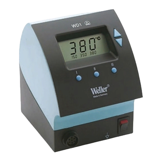
Seite 2: Geräteübersicht
WD 1 (M) / WD 1000 WD 1 (M) WD 1000 Geräteübersicht Display UP-Taste DOWN-Taste Temperaturtaste III Temperaturtaste II Temperaturtaste I Netzschalter Potentialausgleichsbuchse Anschlussbuchse für das Lötwerkzeug 10 USB-Schnittstelle, B-Mini (WD 1M optional) 11 Netzanschluss 12 Netzsicherung 13 Temperaturanzeige 14 Temperatursymbol 15 Zeitfunktion 16 Verriegelung 17 Optische Regelkontrolle... -
Seite 3: Inhaltsverzeichnis
12 Entsorgung ................16 13 Garantie ................... 16 1 Zu dieser Anleitung Wir danken Ihnen für das mit dem Kauf der Weller WD 1 (M) / WD 1000 erwiesene Vertrauen. Bei der Fertigung wurden strengste Qualitätsanforderungen zugrunde gelegt, die eine einwandfreie Funktion des Gerätes sicherstellen. -
Seite 4: Zu Ihrer Sicherheit
Sicherheitshinweise 4 Gerätebeschreibung Die Weller WD 1 (M) / WD 1000 ist eine vielseitig verwendbare Lötstation für professionelle Reparaturarbeiten an elektronischen Baugruppen neuester Technologie in der industriellen Fertigungstechnik sowie im Reparatur- und Laborbereich. Die digitale Regelelektrotechnik gewährleistet zusammen mit einer hochwertigen Sensor- und Wärmeübertragungstechnik im... - Seite 5 Anwahl von Festtemperaturen. Das Erreichen der vorgewählten Temperatur wird durch Blinken der optischen Regelkontrolle („“ Symbol im Display) signalisiert. Die Weller WD 1 (M) / WD 1000 Lötstation bietet folgende weitere Funktionen: Automatische Werkzeugerkennung und Aktivierung der entsprechenden Regelparameter ...
- Seite 6 USB-Schnittstelle Das Steuergeräte WD 1M ist mit einer Mini USB-Schnittstelle (10) ausgerüstet. Zur Nutzung der USB-Schnittstelle steht Ihnen eine Weller-Software auf CD zur Verfügung mit der Sie ein Software Update („Firmware Updater“) an Ihrem Steuergerät durchführen können und das Steuergerät fernbedienen, sowie Temperaturkurven grafisch darstellen, speichern und ausdrucken können („Monitorsoftware“).
-
Seite 7: Gerät In Betrieb Nehmen
WD 1 (M) / WD 1000 7-16 5 Gerät in Betrieb nehmen WARNUNG! Stromschlag und Verbrennungsgefahr Durch unsachgemäßes Anschließen des Steuergeräts besteht Verletzungsgefahr und kann das Gerät beschädigt werden. Beim Betrieb des Steuergeräts besteht Verbrennungsgefahr am Lötwerkzeug. Lesen Sie die beiliegenden Sicherheitshinweise, die Sicherheitshinweise dieser Betriebsanleitung sowie die Anleitung Ihres Steuergeräts vor in Betriebnahme des Steuergeräts vollständig durch und beachten Sie die darin... -
Seite 8: Löten Und Entlöten
8-16 WD 1 (M) / WD 1000 - Permanentes Drücken verstellt den Sollwert im Schnelldurchlauf. Ca. 2 Sekunden nach Loslassen der Einstelltasten erscheint im Display wieder der Istwert des ausgewählten Kanals. 4. Taste UP und DOWN gleichzeitig drücken. Ist der Kanal nun inaktiv, erscheint im Display die Anzeige „OFF“. Ist der Kanal nun aktiviert, erscheint im Display die aktuelle Isttemperatur. -
Seite 9: Sonderfunktionen
Lötspitze und Lötstelle, indem Sie die Lötspitze gut verzinnen. Schalten Sie bei längeren Arbeitspausen das Lötsystem aus oder verwenden Sie die Weller Funktion zur Temperaturabsenkung bei Nichtgebrauch Benetzen Sie die Spitze, bevor Sie den Lötkolben in die Ablage legen. - Seite 10 10-16 WD 1 (M) / WD 1000 Im Display erscheint „FSE“. Die Lötstation ist nun wieder auf die Werkseinstellungen zurückgesetzt. Standby-Temperatur einstellen Nach einer Temperaturabschaltung wird automatisch die Standby- Temperatur eingestellt. Die Isttemperatur wird blinkend angezeigt. Im Display erscheint „STANDBY“ (100 °C –...
- Seite 11 WD 1 (M) / WD 1000 11-16 Temperaturverhalten bei unterschiedlichen Einstellungen der SETBACK- und AUTO OFF-Funktionen Einstellungen Temperaturverhalten ohne Schaltablage SETBACK OFF Time Time [1-99 min] [1-999 min] Lötwerkzeug bleibt auf der eingestellten Löttemperatur. Lötwerkzeug wird bei Nichtgebrauch nach Ablauf der OFF-Zeit Time abgeschaltet.
- Seite 12 12-16 WD 1 (M) / WD 1000 3. Mit Taste I (zurück) oder II (vor) zum nächsten Menüpunkt wechseln. Window-Funktion einstellen Ausgehend von einer eingestellten, verriegelten Temperatur, kann mit Hilfe der WINDOW-Funktion ein Temperaturfenster von ± 99 °C (± 180 °F) eingestellt werden. Hinweis Um die WINDOW-Funktion nutzen zu können, muss die Lötstation im verriegelten Zustand (siehe „Verriegelungsfunktion ein-...
-
Seite 13: Sonderfunktionen Menü 2 Auswählen
WD 1 (M) / WD 1000 13-16 Hinweis Das Entriegeln der Lötstation ist auch mit Hilfe einer Dekodierliste oder dem Reset-Stecker möglich. Sonderfunktionen Menü 2 auswählen Sonderfunktionen Navigation AUTO CHANNEL EXIT HI / LO CONROL 1. Gewünschten Kanal I, II oder III für die Eingabe der Sonderfunktionen auswählen. - Seite 14 14-16 WD 1 (M) / WD 1000 Kalibrierung bei 100 °C / 212 °F ändern 1. Temperaturfühler (0,5 mm) des externen Temperaturmessgeräts in die Temperaturmessspitze einführen. 2. Menüpunkt FCC im Menü 2 auswählen. 3. Taste DOWN drücken. Kalibrierpunkt 100 °C / 212 °F wird ausgewählt. Die Lötspitze wird nun auf 100 °C / 212 °F aufgeheizt.
-
Seite 15: Zurücksetzen Auf Werkseinstellungen
WD 1 (M) / WD 1000 15-16 Kalibrierung auf Werkseinstellungen zurücksetzen 1. Menüpunkt FCC im Menü 2 auswählen. 2. Taste III gedrückt halten. 3. Anschließend Tasten UP und DOWN gleichzeitig drücken. Im Display erscheint „FSE“ (Factory Setting Enabled). Die Lötstation ist nun wieder auf die Werkskalibrierung zurückgesetzt. -
Seite 16: Zubehör
Käufers nach §§ 478, 479 BGB. Aus einer von uns abgegebenen Garantie haften wir nur, wenn die Beschaffenheits- oder Haltbarkeitsgarantie von uns schriftlich und unter Verwendung des Begriffs „Garantie“ abgegeben worden ist. Technische Änderungen vorbehalten! Die aktualisierten Betriebsanleitungen finden Sie unter www.weller-tools.com. - Seite 17 WD 1 (M) / WD 1000 Operating Manual...
-
Seite 18: Equipment Overview
WD 1 (M) / WD 1000 WD 1 (M) WD 1000 Equipment overview Display UP button DOWN button Temperature button III Temperature button II Temperature button I Mains switch Equipotential-bonding socket Connecting socket for soldering tool 10 USB interface, B-Mini (WD 1M optional) 11 Mains connection 12 Mains system fuse... -
Seite 19: About These Instructions
1 About these instructions Thank you for placing your trust in our company by purchasing the Weller WD 1 (M) / WD 1000. The device has been manufactured in accordance with the most rigorous quality standards, which ensure that the device operates perfectly. -
Seite 20: Specified Use
booklet 4 Device description The Weller WD 1 (M) / WD 1000 is a versatile soldering station for performing professional repair work on state-of-the-art electronic assemblies in the industrial engineering sector as well as repair workshops and laboratories. - Seite 21 A flashing optical control check ("" symbol on display) indicates that the preselected tool temperature has been reached. The Weller WD 1 (M) / WD 1000 soldering station also offers the following functions: Automatic tool detection and activation of corresponding control parameters ...
-
Seite 22: Starting Up The Device
USB port The control units WD 1M is fitted with a mini USB interface (10). For the purpose of using the USB port, Weller software is available on a CD with which you can carry out a software update ("Firmware Updater“) on your control unit and ... -
Seite 23: Operating The Device
WD 1 (M) / WD 1000 7-16 Continuous illumination indicates that the system is warming up. Flashing light indicates that the preselected temperature has been reached. Note Please refer to the accessories section on page 16 for a list of tools that can be connected to the WD 1 (M) / WD 1000. -
Seite 24: Special Functions
Switch off the system if you do not intend to use the soldering iron for longer periods or activate the Weller temperature reduction function Coat the tip before placing the soldering iron in the holder. - Seite 25 WD 1 (M) / WD 1000 9-16 Selecting Menu 1 special functions Special functions Navigation STANDBY SETBACK AUTO OFF OFFSET WINDOW EXIT °C / °F 1. Press and hold down the UP and DOWN buttons simultaneously. "– 1 –“ appears in the display after 2 s. 2.
- Seite 26 10-16 WD 1 (M) / WD 1000 "1-99 min“: setback ON (individually settable setback time) 1. Select the menu item SETBACK in Menu 1. 2. Set the setback value with the UP or DOWN button. 3. Press the I (back) or II (forwards) button to switch to the next menu item.
- Seite 27 WD 1 (M) / WD 1000 11-16 Temperature performance with different settings of the SETBACK and AUTO OFF functions Settings Temperature performance without switching holder SETBACK time OFF time [1-99 mins] [1-999 mins] Soldering tool remains at the set soldering temperature. Soldering tool is switched off when not in use after the OFF time Time...
- Seite 28 12-16 WD 1 (M) / WD 1000 Setting the temperature offset The real soldering-tip temperature can be adapted by entering a temperature offset around ± 40 °C (± 72 °F). 1. Select the menu item OFFSET in Menu 1. 2. Set the Auto-OFFSET temperature value with the UP or DOWN button.
- Seite 29 WD 1 (M) / WD 1000 13-16 Unlock the soldering station: 1. Select the menu item LOCK in Menu 1. "ON“ appears in the display. The padlock symbol is displayed. 2. Enter the 3-digit lock code with the UP or DOWN button. 3.
-
Seite 30: Risk Of Burns
14-16 WD 1 (M) / WD 1000 WARNING! Risk of burns The soldering tool becomes hot during the calibration process. There is a risk of burns from touching the tool. Keep the hot soldering tool well away from flammable objects and do not touch. -
Seite 31: Resetting To Factory Settings
WD 1 (M) / WD 1000 15-16 6. Press button II (Set) to confirm the value. The temperature deviation is now reset to 0. Calibration at 450 °C / 842 °F is now concluded. 7. Exit Menu 2 with button III. Resetting calibration to factory settings 1. -
Seite 32: Accessories
We shall assume liability for warranties supplied by us only if the quality guarantee or service warranty has been submitted in writing and using the term "Warranty". Subject to technical alterations and amendments! See the updated operating instructions at www.weller-tools.com. - Seite 33 WD 1 (M) / WD 1000 Manual de uso...
-
Seite 34: Esquema Del Aparato
WD 1 (M) / WD 1000 WD 1 (M) WD 1000 Esquema del aparato Pantalla Tecla UP (subir) Tecla DOWN (bajar) 4. Tecla de la temperatura III Tecla de la temperatura II Tecla de la temperatura I Interruptor principal Conector hembra para el equipotencial Clavija de conexión para el soldador... -
Seite 35: Información Breve Sobre Este Manual
13 Garantía ................... 18 Información breve sobre este manual Le agradecemos mucho la compra del equipo Weller WD 1 (M) / WD 1000 y la confianza depositada en nosotros. La fabricación de este aparato está sometida a los más rigurosos controles de calidad para garantizar un perfecto funcionamiento del mismo. -
Seite 36: Por Su Propia Seguridad
4-18 WD 1 (M) / WD 1000 2 Por su propia seguridad La estación de soldar WD 1 (M) / WD 1000 ha sido fabricada según los últimos avances tecnológicos y de conformidad con la normativa de seguridad técnica. No obstante, existe riesgo de que se produzcan daños personales o materiales si no se respetan las instrucciones de seguridad que figuran en el folleto de seguridad adjunto, así... -
Seite 37: Descripción Del Aparato
WD 1 (M) / WD 1000 5-18 4 Descripción del aparato La Weller WD 1 (M) / WD 1000 es una estación de soldar muy versátil para trabajos de reparación profesionales de componentes electrónicos de última generación en la técnica industrial de producción, así... - Seite 38 Las unidades de control WD 1M y WD 1000 están equipadas con una interfaz Mini USB (10). Para poder utilizar la interfaz USB, usted dispone de un software de Weller en el CD con el cual puede efectuar una actualización de software (“Firmware Updater“) en su control y...
-
Seite 39: Puesta En Marcha Del Aparato
WD 1 (M) / WD 1000 7-18 5 Puesta en marcha del aparato ¡ADVERTENCIA! Peligro de descarga eléctrica y de sufrir quemaduras Si se conecta inadecuadamente la unidad de control existe peligro de provocar daños personales y materiales. Durante el funcionamiento de la unidad de control existe peligro de sufrir quemaduras con el soldador. -
Seite 40: Manejo Del Aparato
8-18 WD 1 (M) / WD 1000 6 Manejo del aparato Ajuste de la temperatura Ajuste individual de la temperatura 1. Conectar el aparato con el interruptor principal (7). La pantalla indica la temperatura real. 2. Pulsar la tecla UP o DOWN. La pantalla muestra al valor de referencia ajustado. - Seite 41 En caso de pausas prolongadas desconectar el equipo y utilizar la función de reducción de la temperatura de la estación Weller. Humedecer la punta de soldar antes de colocar el soldador en el soporte.
-
Seite 42: Funciones Especiales
10-18 WD 1 (M) / WD 1000 7 Funciones especiales Las funciones especiales se dividen en 2 niveles de menú: 2 s ➾ Menú 1 Menú 1 con los posibles ajustes de temperatura STANDBY, desconexión de la temperatura (función de reducción de la temperatura (SETBACK)), tiempo de 4 s ➾... - Seite 43 WD 1 (M) / WD 1000 11-18 1. Seleccionar el punto de menú STANDBY en el menú 1. 2. Ajustar el valor de referencia de la temperatura standby con la tecla UP o DOWN. 3. Mediante la tecla I (atrás) o II (siguiente) es posible avanzar o retroceder en el menú.
- Seite 44 12-18 WD 1 (M) / WD 1000 Comportamiento térmico con diferentes ajustes de las funciones SETBACK y AUTO OFF Ajustes Comportamiento térmico sin soporte de seguridad SETBACK OFF Time Time [1-99 min] [1-999 min] La herramienta de soldar mantiene la temperatura de soldadura ajustada.
- Seite 45 WD 1 (M) / WD 1000 13-18 Ajustar el offset de temperatura La temperatura real de la cabeza del soldador se puede adaptar mediante la entrada de un offset de temperatura de aproximadamente ± 40 °C (± 72 °F). 1. Seleccionar el punto de menú OFFSET en el menú 1. 2.
- Seite 46 14-18 WD 1 (M) / WD 1000 Desbloqueo de la estación de soldar: 1. Seleccionar el punto de menú LOCK en el menú 1. En la pantalla se muestra “ON“. Se muestra el símbolo de la llave. 2. Introducir el código de bloqueo de tres dígitos con la tecla UP o DOWN.
- Seite 47 WD 1 (M) / WD 1000 15-18 Manejo de la función de calibración (Factory Calibration Check) La función FCC permite comprobar la precisión de temperatura de la estación de soldar y compensar las posibles desviaciones. A tal fin es necesario medir la temperatura de la cabeza del soldador con un aparato de medición de temperatura externo y una punta de medición de temperatura asignada a la herramienta de soldar.
- Seite 48 16-18 WD 1 (M) / WD 1000 Cambiar la calibración con 450 °C / 842 °F 1. Introducir la sonda de temperatura (0,5 mm) del aparato de medición de temperatura externo en la punta de medición de temperatura. 2. Seleccionar el punto de menú FCC en el menú 2. 3.
-
Seite 49: Restaurar Los Ajustes De Fábrica
WD 1 (M) / WD 1000 17-18 8 Restaurar los ajustes de fábrica Restablecimiento de las funciones especiales Esta función se describe en el apartado 7.1 "Selección de funzione especiales menú 1“, "Restablecimiento de los ajustes de fábrica para las funciones especiales“ de la página 10. Restaurar los ajustes de fábrica de la calibración Esta función se describe en el apartado 7.2 "Selección de funzione especiales menú... -
Seite 50: Accesorios
Únicamente nos responsabilizamos de los derechos de garantía cuando la garantía de compra y vida útil del aparato haya sido entregada por nosotros por escrito y utilizando el término "Garantía". ¡Reservado el derecho a realizar modificaciones técnicas! Encontrará los manuales de instrucciones actualizados en www.weller-tools.com. - Seite 51 WD 1 / WD 1000 – Circuit Diagram...
- Seite 52 WD 1 / WD 1000 – Exploded Drawing...
- Seite 53 WD 1M / WD 1000 – Circuit Diagram...
- Seite 54 WD 1M / WD 1000 – Exploded Drawing...
- Seite 55 GERMANY GREAT BRITAIN Weller Tools GmbH Apex Tool Group Carl-Benz-Str. 2 (UK Operations) Ltd. 74354 Besigheim Floor Pennine House Phone: +49 (0) 7143 580-0 Washington, Tyne & Wear Fax: +49 (0) 7143 580-108 NE37 1LY Phone: +44 (0) 191 419 7700...