Werbung
Verfügbare Sprachen
Verfügbare Sprachen
Quicklinks
Werbung
Kapitel

Verwandte Anleitungen für autosen AL001


Inhaltszusammenfassung für autosen AL001
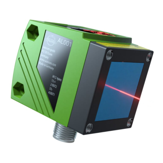
- Seite 1 All manuals and user guides at all-guides.com Bedienungsanleitung Optischer Abstandssensor Operating instructions Optical distance sensor Notice d‘utilisation Détecteur de distance optique Istruzioni per l'uso Sensore ottico di distanza AL001 autosen Made in Germany...
-
Seite 2: Inhaltsverzeichnis
All manuals and user guides at all-guides.com Inhalt 1 Vorbemerkung �����������������������������������������������������������������������������������������������������4 1�1 Verwendete Symbole �������������������������������������������������������������������������������������4 1�2 Verwendete Warnhinweise ����������������������������������������������������������������������������4 2 Sicherheitshinweise ���������������������������������������������������������������������������������������������4 3 Bestimmungsgemäße Verwendung ���������������������������������������������������������������������6 3�1 Einsatzbereiche ���������������������������������������������������������������������������������������������6 4 Funktionen �����������������������������������������������������������������������������������������������������������6 4�1 Ausgangsfunktion Hysterese �������������������������������������������������������������������������6 4�2 Ausgangsfunktion Fenster �����������������������������������������������������������������������������6 4�3 Ausgangsfunktion Analog ������������������������������������������������������������������������������6 5 Montage ���������������������������������������������������������������������������������������������������������������6 5�1 Montagebedingungen ������������������������������������������������������������������������������������6... - Seite 3 All manuals and user guides at all-guides.com 10�2�4 Hysteresefunktion �����������������������������������������������������������������������������17 10�2�5 Schaltpunkt für Hysteresefunktion OUT1 einstellen �������������������������18 10�2�6 Fensterfunktion ���������������������������������������������������������������������������������18 10�2�7 Schaltpunkte für Fensterfunktion OUT1 einstellen ���������������������������19 10�2�8 OUT2 konfigurieren ��������������������������������������������������������������������������20 10�2�9 Schaltpunkt für Hysteresefunktion OUT2 einstellen �������������������������20 10�2�10 Schaltpunkte für Fensterfunktion OUT2 einstellen �������������������������20 10�2�11 Messbereich (Analogausgang) skalieren ����������������������������������������20 10�3 Teach-Modus ���������������������������������������������������������������������������������������������22 10�3�1 Messfrequenz einstellen �������������������������������������������������������������������22...
-
Seite 4: Vorbemerkung
All manuals and user guides at all-guides.com 1 Vorbemerkung 1.1 Verwendete Symbole ► Handlungsanweisung > Reaktion, Ergebnis […] Bezeichnung von Tasten, Schaltflächen oder Anzeigen → Querverweis Wichtiger Hinweis Fehlfunktionen oder Störungen sind bei Nichtbeachtung möglich� Information Ergänzender Hinweis� 1.2 Verwendete Warnhinweise WARNUNG Warnung vor schweren Personenschäden�... -
Seite 5: Label Für Versorgungskabel
All manuals and user guides at all-guides.com WARNUNG Sichtbares Laserlicht; Laserschutzklasse 2� Die Verwendung von anderen Bedieneinrichtungen oder -einstellungen kann zu gefährlicher Strahlungsexposition führen� Schädigung der Netzhaut ist möglich� ► Nicht in den Laserstrahl blicken! ► Die beigelegten Aufkleber (Warnhinweis Laser) in unmittelbarer Nähe des Geräts anbringen�... -
Seite 6: Bestimmungsgemäße Verwendung
All manuals and user guides at all-guides.com 3 Bestimmungsgemäße Verwendung Das Gerät wird als optischer Abstandssensor eingesetzt� 3.1 Einsatzbereiche • Der optische Abstandssensor misst Entfernungen von 0,2���10 m� • Er besitzt eine Hintergrundausblendung >10���100 m� • Der Messwert wird in einem 10-Segment-Display angezeigt� •... -
Seite 7: 5�2 Montagezubehör
All manuals and user guides at all-guides.com 5.2 Montagezubehör Das Gerät wird ohne Montagezubehör geliefert� Montagebeispiel: Befestigungswinkel autosen AA917 DE DE... -
Seite 8: Elektrischer Anschluss
Das Gerät darf nur von einer Elektrofachkraft installiert werden� ► Befolgen Sie die nationalen und internationalen Vorschriften zur Errichtung elektrotechnischer Anlagen� ► Spannungsversorgung nach EN 50178, SELV, PELV sicherstellen� AL001: cULus, Supply Class 2 ► Anlage spannungsfrei schalten� ► Gerät wie folgt anschließen: AL001 PNP... -
Seite 9: Bedien- Und Anzeigeelemente
All manuals and user guides at all-guides.com 7 Bedien- und Anzeigeelemente 1: 4x LED grün Leuchtende LED = Power und eingestellte Anzeigeeinheit (mm, m, inch) 2: 4x LED gelb Anzeige des Schaltzustands; leuchtet, wenn der jeweilige (zwei nicht belegt) Ausgang durchgeschaltet ist� 3: 4-stellige Anzeige der gemessenen Entfernung, der Parameter und alphanumerische... -
Seite 10: Menü
All manuals and user guides at all-guides.com 8 Menü 8.1 Menü-Struktur = [MODE / ENTER] = [SET]... -
Seite 11: 8�2 Menü-Erläuterung
All manuals and user guides at all-guides.com 8.2 Menü-Erläuterung Die Werkseinstellungen befinden sich am Ende der Anleitung (→ 13 Werkseinstellung). Konfiguration für Ausgang 1 Es sind 4 Schaltfunktionen einstellbar: [Hno], [Hnc], [Fno], [Fnc] → 10.2.3 OUT1 konfigurieren Schaltpunkt für Hysteresefunktion OUT1 Grenzwert, bei dem der Ausgang in Hysteresefunktion seinen Schaltzustand ändert (Objekt näher / weiter als eingestellte Entfernung)�... - Seite 12 All manuals and user guides at all-guides.com Teachmodus Vorwahl "Ausgaberate" oder "Reproduzierbarkeit" → 10.3 Teachmodus Erweiterte Funktionen Druck auf [SET] öffnet das Untermenü "Erweiterte Funktionen" → 10.4 Erweiterte Funktionen Verzögerungszeit für die Schaltausgänge [dSx] = Einschaltverzögerung; [drx] = Ausschaltverzögerung� Der Ausgang ändert seinen Schaltzustand nicht sofort bei Eintritt des Schaltereignisses, sondern erst nach Ablauf der Verzögerungszeit�...
-
Seite 13: Betriebsarten
All manuals and user guides at all-guides.com 9 Betriebsarten 9.1 Run-Modus Der Run-Modus entspricht dem normalen Arbeitsbetrieb� Nach dem Einschalten der Versorgungsspannung befindet sich das Gerät im Run- Modus� Es führt seine Überwachungsfunktion aus und erzeugt Ausgangssignale entsprechend den eingestellten Parametern� Das Display zeigt die aktuelle Entfernung an, die gelben LEDs signalisieren den Schaltzustand der Ausgänge�... -
Seite 14: Parametrierung
All manuals and user guides at all-guides.com 10 Parametrierung Das Gerät verbleibt während der Parametrierung intern im Arbeitsbetrieb� Es führt seine Überwachungsfunktionen mit den bestehenden Parametern weiter aus, bis die Veränderung abgeschlossen ist� 10.1 Parametrierung allgemein 10.1.1 Einstellung eines Parameterwertes Anzeigeeinheit [Uni] einstellen, bevor die Werte für die Parameter festgelegt werden�... -
Seite 15: 10�1�2 Wechsel Von Menü-Ebene 1 Zu Menü-Ebene 2
All manuals and user guides at all-guides.com 10.1.2 Wechsel von Menü-Ebene 1 zu Menü-Ebene 2 ► [MODE/ENTER] so oft drücken, bis [EF] angezeigt wird. MODE ENTER ► Kurz [SET] drücken� > Der erste Parameter des Untermenüs wird angezeigt (hier: [dr1])� MODE ENTER 10.1.3 Elektronisches Schloss... -
Seite 16: 10�2 Parametrierung Grundeinstellungen
All manuals and user guides at all-guides.com 10.2 Parametrierung Grundeinstellungen 10.2.1 Anzeigeeinheit wählen [Uni] einstellen, bevor die Werte für die Parameter [SPx], [nSPx], [FSPx], [ASP], [AEP] festgelegt werden� Bei nachträglicher Änderung der Anzeigeeinheit können Rundungsfehler bei der internen Umrechnung die eingestellten Werte verfälschen� ►... -
Seite 17: Beispiel Hno
All manuals and user guides at all-guides.com 10.2.4 Hysteresefunktion Die Hysterese hält den Schaltzustand des Ausgangs stabil, wenn der Messwert um den Schaltabstand herum schwankt� Der Ein- und Rückschaltpunkt sind in beiden Fällen symmetrisch um den gewählten Schaltpunkt [SPx] angeordnet� Der Abstand zwischen Ein- und Rückschaltpunkt ist die Hysterese;... -
Seite 18: Beispiel Für Ausgangsfunktion [Hno]
All manuals and user guides at all-guides.com Schaltzustand der Ausgänge Ausgangsfunktion Objektabstand (D) Schaltzustand [Hno] D < [SPx] geschlossen D > [SPx] offen [Hnc] D < [SPx] offen D > [SPx] geschlossen Beispiel für Ausgangsfunktion [Hno] Messfrequenz 15 Hz, Entfernung zum Objekt 1200 mm, Grauwert (18 % Remission): Hysterese = ±... -
Seite 19: 10�2�7 Schaltpunkte Für Fensterfunktion Out1 Einstellen
All manuals and user guides at all-guides.com Schaltet, wenn Objekt erkannt wird [nSPx] = Schaltpunkt "Nah"; [FSPx] = Schaltpunkt "Fern"; FE = Fenster Bewegt sich der Messwert zwischen Schaltpunkt "Nah" [nSPx] und Schaltpunkt "Fern" [FSPx], ist der Ausgang geschlossen (wenn [OUx] = [Fno])� Schaltzustand der Ausgänge Ausgangsfunktion Objektabstand (D) -
Seite 20: 10�2�8 Out2 Konfigurieren
All manuals and user guides at all-guides.com 10.2.8 OUT2 konfigurieren ► [OU2] wählen� ► Schaltfunktionen oder Analogsignale einstellen: • [Hno] = Hysteresefunktion / normally open (Schließer) • [Hnc] = Hysteresefunktion / normally closed (Öffner) • [Fno] = Fensterfunktion / normally open (Schließer) •... -
Seite 21: Messbereich Skaliert
All manuals and user guides at all-guides.com Stromausgang 4 ... 20 mA Werkseinstellung Messbereich skaliert I [mA] I [mA] 0(ASP) 10000(AEP) MEW = Messbereichsendwert Im eingestellten Messbereich liegt das Ausgangssignal zwischen 4 und 20 mA� Weiter werden Störungen signalisiert: Zu viel Licht oder Objekt zu nah: 3,5 mA bei steigender Flanke ([ASP] < [AEP]), 20,5 mA bei fallender Flanke ([ASP] >... -
Seite 22: 10�3 Teach-Modus
All manuals and user guides at all-guides.com 10.3 Teach-Modus 10.3.1 Messfrequenz einstellen Die Messfrequenz gibt die Zeitdauer an, nach der spätestens ein neues Messergebnis vorliegt und die Ausgänge aktualisiert werden� Die Schaltfrequenz beträgt typisch ca� 1/3 der Messfrequenz� ► [TEAC] wählen, dann [SET] drücken und festhalten, bis [WAIT] erscheint�... -
Seite 23: 10�3�3 Tabelle Reproduzierbarkeit Und Genauigkeit
All manuals and user guides at all-guides.com 10.3.3 Tabelle Reproduzierbarkeit und Genauigkeit Werte für Messfrequenz 15 Hz, Fremdlicht max. 40 klx* Reproduzierbarkeit Genauigkeit Entfernung weiß grau weiß grau in [mm] 90 % Remission 18 % Remission 90 % Remission 18 % Remission 200���1000 ±... -
Seite 24: 10�4 Erweiterte Funktionen
All manuals and user guides at all-guides.com 10.4 Erweiterte Funktionen 10.4.1 Verzögerungszeit für Schaltausgänge einstellen ► [EF] wählen� ► [SET] drücken, um ins Menü [EF] zu wechseln� ► Mit [MODE/ENTER] Parameter wählen: [dSx] = Einschaltverzögerung; [drx] = Ausschaltverzögerung ► Mit [SET] Parameterwert einstellen: Einstellbereich [s]: 0 / 0,1���5 s in Schritten von 0,1 s (0 = Verzögerungszeit ist nicht aktiv) ►... -
Seite 25: Io-Link
Des Weiteren ist die Kommunikation über eine Punkt-zu-Punkt-Verbindung mit einem USB-Adapterkabel möglich� Weitere Informationen zu IO-Link finden Sie unter www�autosen�com� 11.2 Gerätespezifische Informationen Die zur Konfiguration des IO-Link-Gerätes notwendigen IODDs sowie detaillierte Informationen über Sensorwerte, Diagnoseinformationen und Parameter finden Sie in der tabellarischen Übersicht unter www�autosen�com�... -
Seite 26: Inbetriebnahme / Betrieb
All manuals and user guides at all-guides.com 12 Inbetriebnahme / Betrieb ► Nach Montage, elektrischem Anschluss und Programmierung prüfen, ob das Gerät sicher funktioniert� > Bei korrekter Inbetriebnahme wird die Entfernung zum Objekt angezeigt� Lebensdauer einer Laserdiode: 50000 Stunden 12.1 Fehleranzeigen Stromausgang / Schaltausgang Spannungsausgang... -
Seite 27: Wartung, Instandsetzung, Entsorgung
All manuals and user guides at all-guides.com 13 Wartung, Instandsetzung, Entsorgung Die Instandsetzung defekter Sensoren ist nur durch den Hersteller erlaubt� ► Die Frontscheibe des Gerätes von Verschmutzung freihalten� ► Das Gerät nach Gebrauch umweltgerecht gemäß den gültigen nationalen Bestimmungen entsorgen� 14 Werkseinstellung Parameter Einstellbereich... - Seite 28 All manuals and user guides at all-guides.com M12x1 Maße in mm 1: 4-stellige alphanumerische Anzeige / LED-Funktionsanzeigen 2: Programmiertasten...
- Seite 29 All manuals and user guides at all-guides.com...
- Seite 30 All manuals and user guides at all-guides.com Contents 1 Preliminary note �������������������������������������������������������������������������������������������������32 1�1 Symbols used ����������������������������������������������������������������������������������������������32 1�2 Warning signs used �������������������������������������������������������������������������������������32 2 Safety instructions ���������������������������������������������������������������������������������������������32 3 Functions and features ��������������������������������������������������������������������������������������34 3�1 Applications �������������������������������������������������������������������������������������������������34 4 Functions �����������������������������������������������������������������������������������������������������������34 4�1 Output function hysteresis ���������������������������������������������������������������������������34 4�2 Output function window �������������������������������������������������������������������������������34 4�3 Analogue output function �����������������������������������������������������������������������������34 5 Installation����������������������������������������������������������������������������������������������������������34...
- Seite 31 All manuals and user guides at all-guides.com 10�2�4 Hysteresis function ���������������������������������������������������������������������������45 10�2�5 Setting of the switch point for hysteresis function OUT1 ������������������46 10�2�6 Window function �������������������������������������������������������������������������������46 10�2�7 Setting of the switch points for window function OUT1 ��������������������47 10�2�8 Configuration of OUT1 ����������������������������������������������������������������������48 10�2�9 Setting of the switch point for hysteresis function OUT2 ������������������48 10�2�10 Setting of the switch points for window function OUT2 ������������������48 10�2�11 Scaling of the measuring range (analogue output) �������������������������48...
-
Seite 32: Preliminary Note
All manuals and user guides at all-guides.com 1 Preliminary note 1.1 Symbols used ► Instruction > Reaction, result […] Designation of pushbuttons, buttons or indications → Cross-reference Important note Non-compliance can result in malfunctions or interference� Information Supplementary note� 1.2 Warning signs used WARNING Warning of serious personal injury�... -
Seite 33: Product Label
All manuals and user guides at all-guides.com WARNING Visible laser light; laser protection class 2� Use of controls or adjustments other than those specified herein may result in hazardous radiation exposure� Damage to the retina is possible� ► Do not stare into the laser beam! ►... -
Seite 34: Functions And Features
All manuals and user guides at all-guides.com 3 Functions and features The unit is used as an optical distance sensor� 3.1 Applications • The optical distance sensor measures distances between 0�2 and 10 m� • It has a background suppression at > 10���100 m� •... -
Seite 35: 5�2 Mounting Accessories
All manuals and user guides at all-guides.com 5.2 Mounting accessories The unit is supplied without mounting accessories� Example mounting: autosen AA917... -
Seite 36: Electrical Connection
► The national and international regulations for the installation of electrical equipment must be adhered to� ► Ensure voltage supply according to EN 50178, SELV, PELV� AL001: cULus, Supply Class 2 ► Disconnect power� ► Connect the unit as follows:... -
Seite 37: Operating And Display Elements
All manuals and user guides at all-guides.com 7 Operating and display elements 1: 4 x LED green Lighting LED = power and set display unit (mm, m, inch) 2: 4 x LED yellow Indication of the switching status; lights, if the corresponding (two not output is switched�... -
Seite 38: Menu
All manuals and user guides at all-guides.com 8 Menu 8.1 Menu structure = [MODE / ENTER] = [SET]... -
Seite 39: 8�2 Explanation Of The Menu
All manuals and user guides at all-guides.com 8.2 Explanation of the menu For the factory settings please refer to the end of these instructions (→ 13 Factory setting). Configuration for output 1 4 switching functions can be selected: [Hno], [Hnc], [Fno], [Fnc] → 10.2.3 Configuration of OUT1 Switch point for hysteresis function OUT1 Limit value at which the output with selected hysteresis function changes its switching state (object nearer/farther than distance set)�... -
Seite 40: Display Setting
All manuals and user guides at all-guides.com Analogue end point Measured value at which 20 mA / 10 V are provided� [AEP] is only active if [OU2] = [I] or [U]� → 10.2.11 Scaling of the measuring range (analogue output) Teach mode Selection "sampling rate"... -
Seite 41: Operating Modes
All manuals and user guides at all-guides.com 9 Operating modes 9.1 Run mode The run mode is the normal operating mode� After power on the unit is in the Run mode� It carries out its monitoring function and generates output signals according to the set parameters� The display indicates the current distance, the yellow LEDs signal the switching status of the outputs�... -
Seite 42: Parameter Setting
All manuals and user guides at all-guides.com 10 Parameter setting During parameter setting the unit remains internally in the operating mode� It continues its monitoring function with the existing parameters until the change has been finished� 10.1 Parameter setting in general 10.1.1 Setting of the parameter value Select the display unit [Uni] before you define the values for the parameters�... -
Seite 43: 10�1�2 Change From Menu Level 1 To Menu Level 2
All manuals and user guides at all-guides.com 10.1.2 Change from menu level 1 to menu level 2 ► Press [MODE/ENTER] several times until [EF] is displayed. MODE ENTER ► Press [SET] briefly� > The first parameter of the sub-menu is displayed (here: [dr1])�... -
Seite 44: 10�2 Configuration Of The Basic Settings
All manuals and user guides at all-guides.com 10.2 Configuration of the basic settings 10.2.1 Selection of the display unit Set [Uni] before the values for the parameters [SPx], [nSPx], [FSPx], [ASP], [AEP] are defined� In case of subsequent changes of the display unit rounding errors during internal conversion to other units may falsify the set values�... -
Seite 45: 10�2�4 Hysteresis Function
All manuals and user guides at all-guides.com 10.2.4 Hysteresis function The hysteresis keeps the switching state of the output stable if the measured value varies about the sensing range� In either case set and reset points are symmetrically arranged around the selected switch point [SPx]� The hysteresis is the distance between set and reset points;... -
Seite 46: 10�2�5 Setting Of The Switch Point For Hysteresis Function Out1
All manuals and user guides at all-guides.com Switching status of the outputs Output function Object distance (D) Output status [Hno] D < [SPx] Closed D > [SPx] Open [Hnc] D < [SPx] Open D > [SPx] Closed Example of output function [Hno] Sampling rate 15 Hz, distance to the object 1200 mm, grey value (18 % remission): Hysteresis = ±... -
Seite 47: 10�2�7 Setting Of The Switch Points For Window Function Out1
All manuals and user guides at all-guides.com Switches when the object is detected [nSPx] = switch point "near"; [FSPx] = switch point "far"; FE = window If the measured value is between the switch point "near" [nSPx] and the switch point "far"... -
Seite 48: 10�2�8 Configuration Of Out1
All manuals and user guides at all-guides.com 10.2.8 Configuration of OUT1 ► Select [OU2]� ► Set the switching functions or analogue signals: • [Hno] = hysteresis function / normally open • [Hnc] = hysteresis function / normally closed • [Fno] = window function / normally open •... - Seite 49 All manuals and user guides at all-guides.com Current output 4 ... 20 mA Factory setting Measuring range scaled I [mA] I [mA] 0(ASP) 10000(AEP) MEW = final value of the measuring range In the set measuring range the output signal is between 4 and 20 mA� Faults are also displayed: Too much light or object too near: 3�5 mA for a rising edge ([ASP] <...
-
Seite 50: 10�3 Teach Mode
All manuals and user guides at all-guides.com 10.3 Teach mode 10.3.1 Setting of the sampling rate The sampling rate indicates the time after which a new result of measurement is provided and the outputs are updated� The switching frequency is typ� approx� 1/3 of the sampling rate� ►... -
Seite 51: 10�3�3 Table Repeatability And Accuracy
All manuals and user guides at all-guides.com 10.3.3 Table repeatability and accuracy Values for sampling rate 15 Hz, extraneous light of max. 40 klx* Repeatability Accuracy Distance white grey white grey in [mm] 90 % remission 18 % remission 90 % remission 18 % remission 200���1000 ±... -
Seite 52: 10�4 Extended Functions
All manuals and user guides at all-guides.com 10.4 Extended functions 10.4.1 Setting of the time delay for switching outputs ► Select [EF]� ► Press [SET] to change to the menu [EF]� ► Select parameters with [MODE/ENTER]: [dSx] = switch-on delay; [drx] = switch-off delay ►... -
Seite 53: Io-Link
In addition communication is possible via a point-to-point connection with a USB adapter cable� You will find more detailed information about IO-Link at www�autosen�com� 11.2 Device-specific information You will find the IODDs necessary for the configuration of the IO-Link device and detailed information about sensor values, diagnostic information and parameters in the overview table at www�autosen�com�... -
Seite 54: Set-Up / Operation
All manuals and user guides at all-guides.com 12 Set-up / operation ► After mounting, wiring and programming check whether the unit operates correctly� > If the unit has been correctly set up, the distance to the object is indicated� Lifetime of a laser diode: 50000 hours 12.1 Fault indication Possible Current output /... -
Seite 55: Maintenance, Repair And Disposal
All manuals and user guides at all-guides.com 13 Maintenance, repair and disposal Faulty sensors must only be repaired by the manufacturer� ► Keep the front lens of the sensor free from soiling� ► After use dispose of the unit in an environmentally friendly way in accordance with the applicable national regulations�... - Seite 56 All manuals and user guides at all-guides.com M12x1 Dimensions in mm 1: 4-digit alphanumeric display / LED function display 2: programming buttons...
- Seite 57 All manuals and user guides at all-guides.com...
- Seite 58 All manuals and user guides at all-guides.com Contenu 1 Remarque préliminaire ��������������������������������������������������������������������������������������60 1�1 Symboles utilisés �����������������������������������������������������������������������������������������60 1�2 Avertissements utilisés ��������������������������������������������������������������������������������60 2 Consignes de sécurité ���������������������������������������������������������������������������������������60 3 Fonctionnement et caractéristiques �������������������������������������������������������������������62 3�1 Applications �������������������������������������������������������������������������������������������������62 4 Fonctions �����������������������������������������������������������������������������������������������������������62 4�1 Fonction de sortie hystérésis �����������������������������������������������������������������������62 4�2 Fonction de sortie fenêtre ����������������������������������������������������������������������������62 4�3 Fonction de sortie analogique ���������������������������������������������������������������������62 5 Montaggio ����������������������������������������������������������������������������������������������������������63...
- Seite 59 All manuals and user guides at all-guides.com 10�2�4 Fonction hystérésis ���������������������������������������������������������������������������73 10�2�5 Régler le seuil pour la fonction hystérésis OUT1 �����������������������������74 10�2�6 Fonction fenêtre ��������������������������������������������������������������������������������74 10�2�7 Régler les seuils pour la fonction fenêtre OUT1 �������������������������������75 10�2�8 Configurer OUT2 ������������������������������������������������������������������������������76 10�2�9 Régler le seuil pour la fonction hystérésis OUT2 �����������������������������76 10�2�10 Régler les seuils pour la fonction fenêtre OUT2 �����������������������������76 10�2�11 Mise à...
-
Seite 60: Remarque Préliminaire
All manuals and user guides at all-guides.com 1 Remarque préliminaire 1.1 Symboles utilisés ► Action à faire > Retour d'information, résultat […] Désignation d'une touche, d'un bouton ou d'un affichage → Référence Remarque importante Le non-respect peut aboutir à des dysfonctionnements ou perturbations� Information Remarque supplémentaire�... -
Seite 61: Etiquette Du Produit
All manuals and user guides at all-guides.com AVERTISSEMENT Lumière laser visible ; classe de protection laser 2� L'utilisation d'autres éléments de service ou d'autres réglages peut résulter à l'exposition aux rayonnements dangereux� Lésion de la rétine possible� ► Ne pas regarder le faisceau laser ! ►... -
Seite 62: Fonctionnement Et Caractéristiques
All manuals and user guides at all-guides.com 3 Fonctionnement et caractéristiques L'appareil est utilisé comme détecteur de distance optique� 3.1 Applications • Le détecteur de distance optique mesure des distances entre 0,2���10 m� • Il a une suppression de l'arrière-plan >10���100 m� •... -
Seite 63: Conditions De Montage
Les objets réfléchissants situés directement dans le faisceau du détecteur même dans une plage > 100 m doivent être évités par le client� Sinon, les valeurs mesurées peuvent être ambiguës� 5.2 Accessoires de montage L'appareil est fourni sans accessoires de montage� Exemple de montage : autosen AA917... -
Seite 64: Raccordement Électrique
► Raccorder l‘appareil comme suit : AL001 PNP Out 2 Out 2 Out 1 Out 1 Couleurs des fils conducteurs des connecteurs femelles autosen : 1 = BN (brun), 2 = WH (blanc), 3 = BU (bleu), 4 = BK (noir), 5 = GR (gris)�... -
Seite 65: Eléments De Service Et D'indication
All manuals and user guides at all-guides.com 7 Eléments de service et d‘indication 1: 4 x LED verte LED allumée = Alimentation et unité d'affichage réglée (mm, m, inch) 2: 4 x LED jaune Indication de l'état de commutation ; allumée si la sortie (deux non utilisées) correspondante est commutée�... -
Seite 66: Menu
All manuals and user guides at all-guides.com 8 Menu 8.1 Structure du menu = [MODE / ENTER] = [SET]... -
Seite 67: 8�2 Explication Du Menu
All manuals and user guides at all-guides.com 8.2 Explication du menu Les réglages usine se trouvent à la fin de cette notice (→ 13 Réglage usine). Configuration pour la sortie 1 4 fonctions de commutation sont réglables : [Hno], [Hnc], [Fno], [Fnc] → 10.2.3 Configurer OUT1 Seuil pour la fonction hystérésis OUT1 Valeur limite à... - Seite 68 All manuals and user guides at all-guides.com Mode Teach Présélection "taux d'échantillonnage" ou "répétabilité" → 10.3 Mode Teach Fonctions étendues Par l'appui sur [SET] le sous-menu "Fonctions étendues" s'ouvre� → 10.4 Fonctions étendues Temporisation pour les sorties de commutation [dSx] = temporisation à l'enclenchement ;[drx] = temporisation au déclenchement�...
-
Seite 69: Modes De Fonctionnement
All manuals and user guides at all-guides.com 9 Modes de fonctionnement 9.1 Mode Run Le mode Run correspond au mode de fonctionnement normal� Après la mise sous tension l‘appareil se trouve en mode Run� Il exécute ses fonctions de surveillance et génère les signaux de sortie selon les paramètres réglés�... -
Seite 70: Paramétrage
All manuals and user guides at all-guides.com 10 Paramétrage Pendant le paramétrage l‘appareil reste en mode de fonctionnement en interne� Il continue à exécuter ses fonctions de surveillance avec les paramètres précédents jusqu‘à ce que la modification soit validée� 10.1 Paramétrage en général 10.1.1 Réglage d‘une valeur de paramètre Régler l'unité... -
Seite 71: 10�1�2 Changement Du Niveau De Menu 1 Au Niveau De Menu 2
All manuals and user guides at all-guides.com 10.1.2 Changement du niveau de menu 1 au niveau de menu 2 ► Appuyer plusieurs fois sur [MODE/ENTER] jusqu'à ce que [EF] soit affiché. MODE ENTER ► Appuyer brièvement sur [SET]� > Le premier paramètre du sous-menu est affiché... -
Seite 72: 10�2 Paramétrage Des Réglages De Base
All manuals and user guides at all-guides.com 10.2 Paramétrage des réglages de base 10.2.1 Sélectionner l‘unité d‘affichage Régler [Uni] avant de déterminer les valeurs pour les paramètres [SPx], [nSPx], [FSPx], [ASP], [AEP]� En cas d'un changement ultérieur de l'unité d'affichage des erreurs d'arrondi lors de la conversion interne peuvent fausser les valeurs réglées�... -
Seite 73: 10�2�4 Fonction Hystérésis
All manuals and user guides at all-guides.com 10.2.4 Fonction hystérésis L‘hystérésis garantit un état de commutation de la sortie stable en cas de fluctuations de la valeur mesurée autour du seuil de commutation� Dans les deux cas les seuils d‘enclenchement et de déclenchement sont positionnés symétriquement autour du seuil de commutation [SPx]�... -
Seite 74: 10�2�5 Régler Le Seuil Pour La Fonction Hystérésis Out1
All manuals and user guides at all-guides.com Etat de commutation des sorties Fonction de sortie Distance objet (D) Etat de commutation [Hno] D < [SPx] Fermé D > [SPx] Ouvert [Hnc] D < [SPx] Ouvert D > [SPx] Fermé Exemple de fonction de sortie [Hno] Fréquence de mesure 15 Hz, distance à... -
Seite 75: 10�2�7 Régler Les Seuils Pour La Fonction Fenêtre Out1
All manuals and user guides at all-guides.com Commute si l‘objet est détecté [nSPx] = seuil de commutation "proche"; [FSPx] = seuil de commutation "éloigné"; FE = fenêtre Si la valeur mesurée est entre le seuil „proche“ [nSPx] et le seuil „éloigné“ [FSPx], la sortie est fermée (si [OUx] = [Fno])�... -
Seite 76: 10�2�8 Configurer Out2
All manuals and user guides at all-guides.com 10.2.8 Configurer OUT2 ► Sélectionner [OU2]� ► Régler les fonctions de commutation ou les signaux analogiques : • [Hno] = fonction hystérésis / normalement ouvert • [Hnc] = fonction hystérésis / normalement fermé •... - Seite 77 All manuals and user guides at all-guides.com Sortie courant 4 ... 20 mA Réglage usine Etendue de mesure mise à l'échelle I [mA] I [mA] 0(ASP) 10000(AEP) MEW = valeur maxi de l'étendue de mesure Dans l'étendue de mesure réglée le signal de sortie est entre 4 et 20 mA� De plus, des parasites sont signalés : Trop de lumière ou objet trop proche : 3,5 mA pour le front montant ([ASP] <...
-
Seite 78: 10�3 Mode Teach
All manuals and user guides at all-guides.com 10.3 Mode Teach 10.3.1 Régler la fréquence de mesure La fréquence de mesure définit la durée maximale avant qu'un nouveau résultat de mesure soit disponible et que les sorties soient mises à jour� La fréquence de commutation est normalement env�... -
Seite 79: 10�3�3 Table De Répétabilité Et Précision
All manuals and user guides at all-guides.com 10.3.3 Table de répétabilité et précision Valeurs pour la fréquence de mesure 15 Hz, lumière extérieure de max. 40 klx* Répétabilité Précision Distance Blanc Gris Blanc Gris en [mm] rémission 90 % rémission 18 % rémission 90 % rémission 18 % 200���1000... -
Seite 80: 10�4 Fonctions Étendues
All manuals and user guides at all-guides.com 10.4 Fonctions étendues 10.4.1 Régler la temporisation pour les sorties de commutation ► Sélectionner [EF]� ► Appuyer sur [SET] pour passer au menu [EF]� ► En appuyant sur [MODE/ENTER] sélectionner le paramètre : [dSx] = temporisation à... -
Seite 81: Io-Link
De plus, la communication est possible via un raccordement point-à-point avec un câble adaptateur USB� Vous trouverez plus d‘informations sur IO-Link sur www�autosen�com� 11.2 Informations spécifiques à l‘appareil Vous trouverez les IODD nécessaires pour la configuration de l‘appareil IO-Link ainsi que des informations détaillées concernant les valeurs du détecteur, des... -
Seite 82: Mise En Service / Fonctionnement
All manuals and user guides at all-guides.com 12 Mise en service / Fonctionnement ► Après le montage, le raccordement électrique et la programmation, vérifier le bon fonctionnement de l‘appareil� > En cas d‘une mise en service correcte, la distance à l‘objet est affichée� Durée de vie d'une diode laser : 50000 heures 12.1 Messages d’erreur Sortie de... -
Seite 83: Entretien, Réparation Et Élimination
All manuals and user guides at all-guides.com 13 Entretien, réparation et élimination Des détecteurs défectueux ne doivent être réparés que par le fabricant� ► Dégager le panneu transparent situé devant la lentille de tout encrassement� ► S‘assurer d‘une élimination écologique de l‘appareil après son usage selon les règlements nationaux en vigueur�... - Seite 84 All manuals and user guides at all-guides.com M12x1 Dimensions en mm 1: affichage alphanumérique à 4 digits / indication de fonction par LED 2: boutons de programmation...
- Seite 85 All manuals and user guides at all-guides.com...
- Seite 86 All manuals and user guides at all-guides.com Contenuto 1 Premessa�����������������������������������������������������������������������������������������������������������88 1�1 Simboli utilizzati �������������������������������������������������������������������������������������������88 1�2 Avvertenze utilizzate ������������������������������������������������������������������������������������88 2 Indicazioni di sicurezza ��������������������������������������������������������������������������������������88 3 Uso conforme ����������������������������������������������������������������������������������������������������90 3�1 Campi di impiego �����������������������������������������������������������������������������������������90 4 Funzioni �������������������������������������������������������������������������������������������������������������90 4�1 Isteresi funzione uscita ��������������������������������������������������������������������������������90 4�2 Finestra funzione uscita �������������������������������������������������������������������������������90 4�3 Funzione uscita analogica ���������������������������������������������������������������������������90 5 Montaggio ����������������������������������������������������������������������������������������������������������90...
- Seite 87 All manuals and user guides at all-guides.com 10�2�4 Funzione isteresi ����������������������������������������������������������������������������102 10�2�5 Impostazione del punto di commutazione per la funzione isteresi OUT1 ����������������������������������������������������������������������������������������������103 10�2�6 Funzione finestra ����������������������������������������������������������������������������103 10�2�7 Impostazione dei punti di commutazione per la funzione finestra OUT1 ����������������������������������������������������������������������������������������������104 10�2�8 Configurazione OUT2 ���������������������������������������������������������������������105 10�2�9 Impostazione del punto di commutazione per la funzione isteresi OUT2 ����������������������������������������������������������������������������������������������105 10�2�10 Impostazione dei punti di commutazione per la funzione finestra...
-
Seite 88: Premessa
All manuals and user guides at all-guides.com 1 Premessa 1.1 Simboli utilizzati ► Istruzioni operative > Reazione, risultato […] Denominazione di tasti, pulsanti o visualizzazioni → Riferimento incrociato Nota importante Rischio di malfunzionamenti o anomalie in caso di mancata osservanza� Informazione Nota aggiuntiva�... -
Seite 89: Etichetta Del Prodotto
All manuals and user guides at all-guides.com AVVERTENZA Luce laser visibile, classe di protezione laser 2� L'impiego di altri dispositivi di comando o impostazioni può comportare un'esposizione pericolosa alle radiazioni� Rischio di danneggiamento della retina� ► Non fissare il raggio laser! ►... -
Seite 90: Uso Conforme
All manuals and user guides at all-guides.com 3 Uso conforme Il dispositivo viene impiegato come sensore ottico di distanza� 3.1 Campi di impiego • Il sensore ottico di distanza misura le distanze da 0,2…10 m� • Esso prevede una soppressione dello sfondo >10…100 m� •... -
Seite 91: 5�2 Accessori Di Montaggio
All manuals and user guides at all-guides.com 5.2 Accessori di montaggio Il dispositivo viene fornito privo di accessori di montaggio� Esempio di montaggio: squadretta di fissaggio autosen AA917... -
Seite 92: Collegamento Elettrico
AL001 PNP Out 2 Out 2 Out 1 Out 1 Colori dei fili dei connettori femmina per cavo di autosen: 1 = BN (marrone), 2 = WH (bianco), 3 = BU (blu), 4 = BK (nero), 5 = GR (grigio)�... -
Seite 93: Elementi Di Comando E Di Indicazione
All manuals and user guides at all-guides.com 7 Elementi di comando e di indicazione 1: 4 LED verdi LED acceso = power e unità di visualizzazione impostata (mm, m, inch) 2: 4 LED gialli Visualizzazione dello stato di commutazione; acceso se la (due non collegati) rispettiva uscita è... -
Seite 94: Menu
All manuals and user guides at all-guides.com 8 Menu 8.1 Struttura del menu = [MODE / ENTER] = [SET]... -
Seite 95: Configurazione Uscita
All manuals and user guides at all-guides.com 8.2 Spiegazione del menu Le impostazioni di fabbrica si trovano in fondo alle istruzioni (→ 13 Impostazione di fabbrica)� Configurazione uscita 1 Possono essere impostate 4 funzioni di commutazione: [Hno], [Hnc], [Fno], [Fnc] → 10.2.3 Configurazione OUT1 Punto di commutazione per funzione isteresi OUT1 Valore limite raggiunto il quale l'uscita con funzione isteresi modifica il suo stato di commutazione (oggetto più... - Seite 96 All manuals and user guides at all-guides.com Punto iniziale analogico Valore letto per il quale vengono trasmessi 4 mA / 0 V� [ASP] attivo solo con [OU2] = [I] o [U]� → 10.2.11 Scalare il campo di misura (uscita analogica) Punto finale analogico Valore letto per il quale vengono trasmessi 20 mA / 10 V�...
-
Seite 97: Modi Operativi
All manuals and user guides at all-guides.com Visualizzazione del numero di versione software → 10.4.4 Visualizzazione del numero di versione software 9 Modi operativi 9.1 Modalità Run La modalità Run corrisponde alla normale modalità operativa� Dopo l'inserimento della tensione d'alimentazione, il dispositivo si trova nella modalità... -
Seite 98: Parametrizzazione
All manuals and user guides at all-guides.com 10 Parametrizzazione Durante la parametrizzazione, internamente il dispositivo rimane in modalità operativa� Prosegue le sue funzioni di monitoraggio con i parametri correnti, finché non viene portata a termine la modifica� 10.1 Informazioni generali sulla parametrizzazione 10.1.1 Impostare il valore di un parametro Prima di definire i valori dei parametri impostare l'unità... -
Seite 99: 10�1�2 Passaggio Dal Livello Di Menu 1 Al Livello Di Menu 2
All manuals and user guides at all-guides.com Impostare altri parametri ► Iniziare di nuovo dal punto 1� Terminare la parametrizzazione ► Attendere 15 s o premere [MODE/ENTER]� > Viene visualizzato l'attuale valore letto� 10.1.2 Passaggio dal livello di menu 1 al livello di menu 2 ►... -
Seite 100: 10�2 Impostazioni Di Base Della Parametrizzazione
All manuals and user guides at all-guides.com Timeout Se durante la procedura di regolazione per 15 s non viene premuto nessun tasto, il dispositivo ritorna nella modalità Run mantenendo invariati i suoi valori� 10.2 Impostazioni di base della parametrizzazione 10.2.1 Selezione dell'unità di visualizzazione Impostare [Uni] prima di definire i valori dei parametri [SPx], [nSPx], [FSPx], [ASP], [AEP]�... -
Seite 101: 10�2�3 Configurazione Out1
All manuals and user guides at all-guides.com 10.2.3 Configurazione OUT1 ► Selezionare [OU1] e impostare le funzioni di commutazione� Funzioni di commutazione: • [Hno] = funzione isteresi / normally open (NO) • [Hnc] = funzione isteresi / normally closed (NC) •... -
Seite 102: 10�2�4 Funzione Isteresi
All manuals and user guides at all-guides.com 10.2.4 Funzione isteresi L'isteresi mantiene stabile lo stato di commutazione dell'uscita quando il valore letto oscilla all'interno del range della distanza di commutazione� In entrambi i casi i punti di attivazione e di disattivazione sono disposti in modo simmetrico attorno al punto di commutazione selezionato [SPx]�... -
Seite 103: Out1
All manuals and user guides at all-guides.com Stato di commutazione delle uscite Funzione uscita Distanza oggetto (D) Stato di commutazione [Hno] D < [SPx] chiuso D > [SPx] aperto [Hnc] D < [SPx] aperto D > [SPx] chiuso Esempio funzione uscita [Hno] Frequenza di misurazione 15 Hz, distanza dall'oggetto 1200 mm, valore scala di grigi (18% riflessione): Isteresi = ±... -
Seite 104: Out1
All manuals and user guides at all-guides.com Attivazione al riconoscimento di un oggetto [nSPx] = punto di commutazione "vicino"; [FSPx] = punto di commutazione "lontano"; FE = finestra Se il valore letto si sposta tra il punto di commutazione "vicino" [nSPx] e il punto di commutazione "lontano"... -
Seite 105: 10�2�8 Configurazione Out2
All manuals and user guides at all-guides.com 10.2.8 Configurazione OUT2 ► Selezionare [OU2]� ► Impostare le funzioni di commutazione o i segnali analogici: • [Hno] = funzione isteresi / normally open (NO) • [Hnc] = funzione isteresi / normally closed (NC) •... - Seite 106 All manuals and user guides at all-guides.com Uscita corrente 4 ... 20 mA Impostazione di fabbrica Campo di misura scalato I [mA] I [mA] 0(ASP) 10000(AEP) MEW = valore finale Nel campo di misura impostato il segnale d'uscita è compreso tra 4 e 20 mA� Vengono inoltre segnalati gli eventuali disturbi: Troppa luce o oggetto troppo vicino: 3,5 mA con fronte di salita ([ASP] <...
-
Seite 107: 10�3 Modalità Teach
All manuals and user guides at all-guides.com 10.3 Modalità Teach 10.3.1 Impostazione della frequenza di misurazione La frequenza di misurazione indica il lasso di tempo massimo trascorso il quale viene fornito un nuovo risultato di misurazione e le uscite vengono aggiornate�... -
Seite 108: 10�3�3 Tabella Ripetibilità E Precisione
All manuals and user guides at all-guides.com 10.3.3 Tabella ripetibilità e precisione Valori per la frequenza di misurazione 15 Hz, luce esterna max. 40 klx* Ripetibilità Precisione Distanza bianco grigio bianco grigio in [mm] 90% riflessione 18 % riflessione 90% riflessione 18 % riflessione 200���1000 ±... -
Seite 109: 10�4 Funzioni Avanzate
All manuals and user guides at all-guides.com 10.4 Funzioni avanzate 10.4.1 Impostazione ritardo per uscite di commutazione ► Selezionare [EF]� ► Premere [SET] per passare al menu [EF]� ► Con [MODE/ENTER] selezionare il parametro: [dSx] = temporizzazione inserimento; [drx] = temporizzazione disinserimento�... -
Seite 110: Io-Link
11.2 Informazioni specifiche sui dispositivi Sul sito www�autosen�com è disponibile una tabella riassuntiva per illustrare gli IODD necessari per la configurazione di un dispositivo IO-Link e le informazioni dettagliate sui valori dei sensori, le informazioni di diagnosi e i parametri�... -
Seite 111: Messa In Funzione / Funzionamento
All manuals and user guides at all-guides.com 12 Messa in funzione / funzionamento ► Al termine delle operazioni di montaggio, collegamento elettrico e programmazione controllare che il dispositivo funzioni correttamente e in modo sicuro� > Se la messa in funzione è stata eseguita correttamente, viene visualizzata la distanza dall'oggetto�... -
Seite 112: Manutenzione, Riparazione, Smaltimento
All manuals and user guides at all-guides.com 13 Manutenzione, riparazione, smaltimento I sensori difettosi possono essere riparati solo dal produttore� ► Tenere pulita la finestra anteriore del dispositivo� ► Al termine dell'uso smaltire il dispositivo secondo le disposizioni nazionali in vigore in materia di tutela ambientale�... - Seite 113 All manuals and user guides at all-guides.com M12x1 Dimensioni in mm 1: Visualizzazione alfanumerica a 4 cifre / indicazioni funzioni LED 2: Tasti di programmazione...
- Seite 114 All manuals and user guides at all-guides.com Technische Daten und weitere Informationen unter: Données techniques et informations supplémentaires sur notre site web à: Technical data and further information at: Dati tecnici e altre informazioni si trovano su : www.autosen.com...