Werbung
Quicklinks
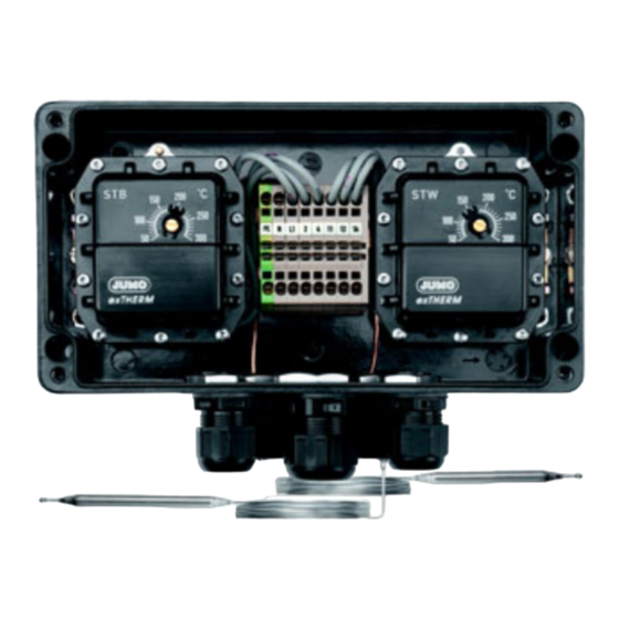
JUMO exTHERM-AT
Explosionsgeschützter Aufbau-Thermostat
für Zone 1, 2, 21 und 22
Explosion-protected surface-mounted thermostat
for zones 1, 2, 21 and 22
Thermostat pour montage en saillie avec protection
contre les explosions pour zones 1, 2, 21 et 22
Betriebsanleitung
Operating Instructions
Notice de mise en service
60505500T90Z002K000
V8.00/DE-EN-FR/00566876/2021-02-03
1
Einleitung
1.1 Verwendung
• Explosionsgeschützte
Aufbau-Thermostate
überwachen oder regeln Temperaturen in explosionsgeschützten Bereichen.
Zone 1 oder 2: Gasen, Dämpfe und Nebel
Zone 21 oder 22: brennbare Stäube und Staub-/Luftgemisch.
• Beim Einsatz in explosionsgefährdeten Bereichen sind die einschlägigen Bestimmun-
gen zur Montage und zum Betrieb von Einrichtungen in diesem Bereich zu beachten.
• Hybride Gemische: Falls am Errichtungsort eine gefährliche Atmosphä-
re, die durch Gase, Dämpfe oder Nebel explosionsgefährdet ist und
gleichzeitig eine solche, die durch brennbare Stäube explosions gefähr-
det ist, auftreten kann, können sich die sicherheitstechnischen Kenngrös-
sen der Gase, Dämpfe, Nebel und der brennbaren Stäube ändern. In
solchen Fällen ist es angezeigt, die Eignung des vorgesehenen Gerätes
durch eine entsprechende Fachstelle überprüfen zu lassen.
1.2 Kennzeichnung
• Ausführung nach
TW
Temperaturwächter
DIN EN 14597 als:
STW
Sicherheits-Temperaturwächter
STB
Sicherheits-Temperaturbegrenzer
• Baumusterprüfung nach:
Normenreihe EN 60079
• Aufbau-Thermostate JUMO exTHERM-AT entsprechen der
DIN EN 60730 (VDE 0631).
• ATEX-
II 2G Ex db eb IIC T4/T5/T6 Gb
Kennzeichnung:
II 2D Ex tb IIIC T85°C/T100°C/T130°C Db
• IECEx-Kennzeichnung
Ex db eb IIC T4/T5/T6 Gb
(optional):
Ex tb IIIC T85°C/T100°C/T130°C Db
• Prüfbescheinigung ATEX:
EPS 11 ATEX 1 354
• Prüfbescheinigung IECEx (optional): IECEx EPS 13.0046
• Prüfbescheinigung EAC-Ex (optional): RU C-DE.HB07.B.00057/20
• Prüfbescheinigung SIL (optional): EPS 11 ATEX 1 354 (SIL 2)
1.3 Sicherheitshinweise
• Das Öffnen des innenliegenden Thermostatgehäuses ist nicht zuläs-
sig. Der Explosionsschutz geht verloren.
• Das Öffnen des Deckels in Zone 21 und 22 ist nicht zulässig.
• Bei Kunststoffkabelverschraubung ist der Einsatz nur zulässig in Bereichen,
die als solche mit geringem Risiko mechanischer Gefährdung eingestuft sind.
• Knicken oder Durchtrennen der Fernleitung führt zum dauerhaften
Ausfall des Gerätes.
• Beim Verlegen der Fernleitung Biegeradius 5 mm einhalten.
• Beim Bruch des Messsystems kann Füllflüssigkeit austreten.
Physikalische und toxikologische Eigenschaften des Ausdehnungsmittels, wel-
ches im Falle eines Messsystembruchs austreten kann:
Regelbereich mit
Gefährliche
Zünd-
wasser-
Skalenendwert
Reaktion
temperatur
gefährdend
°C
°C
Klasse 1,
< +200
nein
+375
schwach
gefährdend
200 +350
nein
+490
ja
350 +500
nein
-
nein
a
Über eine Gesundheitsgefährdung bei kurzzeitiger Einwirkung und geringer Konzentration,
z. B. bei Messsystembruch, gibt es bis jetzt keine einschränkende gesundheitsbehördliche
Stellungnahme. Beim Bruch des Messsystems kann Füllflüssigkeit austreten (max. 3 cm
2 Gerät identifizieren
(1)
Typ
(2)
Regel- bzw. Grenzwertbereich
(3)
Teile-Nr.
(4)
Fabrikationsnummer
(5)
zulässige Umgebungstemperatur
(6)
Ex-Kennzeichnung
(7)
Prüfstelle/-bescheinigung
(8)
Prüfstelle/-bescheinigung (optional)
(9)
Fertigungsjahr
(10)
Fertigungswoche
(11)
lfd. Gerätenummer
(12)
Schaltleistung
3 Montage
3.1 Allgemeines
• Einbaulage nach DIN 16257; NL 0 ... NL 90
3.2 Gehäuse öffnen
3.3 Schaltkopf befestigen
(1) mit starrem Schaft
(2) mit Wandbefestigung
* bei Doppelthermostat
3.4 Schutzrohrmontage
• Die Geräte dürfen nur mit passenden
Schutzrohren betrieben werden.
• Im Betriebsmedium Luft kein Schutzrohr ein-
setzen.
h Bei Ausführung mit Fernleitung Fühler durch
Klemmbügel (1) gegen Herausgleiten si-
chern.
h Der Temperaturfühler (2) muss vollständig in
das Medium eintauchen
Fühler-Ø Schutzrohr-Ø Material Zone
6 mm
8 × 0,75 mm Messing/ 1, 2, 21, 22
Edelstahl
2 × 6 mm 15 × 0,75 mm Messing/ 1, 2, 21, 22
Edelstahl
6 mm
10 × 1,5 mm Edelstahl 0, 1, 2, 20, 21, 22
JUMO Mess- und Regelgeräte GmbH
Pfarrgasse 48 • 1230 Wien, Austria
Tel.: +43 1 610610 • Fax: +43 1 6106140 • info.at@jumo.net • www.jumo.at
JUMO Mess- und Regeltechnik AG
Laubisrütistrasse 70 • 8712 Stäfa, Switzerland
Tel.: +41 44 928 24 44 • Fax: +41 44 928 24 48 • jumostaefa@jumo.net • www.jumo.ch
JUMO Instrument Co. Ltd.
JUMO House • Temple Bank, Riverway • Harlow, Essex, CM20 2DY, UK
Phone: +44 1279 635533 • Fax: +44 1279 625 029 • e-mail: info.uk@jumo.net • www.jumo.co.uk
JUMO Process Control, Inc.
6733 Myers Road • East Syracuse, New York 13057, USA
Phone: (315) 437-5866 • Fax: (315) 437-5860 • Email: info.us@jumo.net • www.jumousa.com
JUMO Régulation SAS
7 Rue des Drapiers • 57075 Metz Cedex 03, France
Tél : +33 3 87 37 53 00 • Fax : +33 3 87 37 89 00 • E-Mail : info.fr@jumo.net • www.jumo.fr
JUMO AUTOMATION S.P.R.L. / P.G.M.B.H. / B.V.B.A
Industriestraße 18 • 4700 Eupen, Belgique
Tél. : +32 87 59 53 00 • Fax : +32 87 74 02 03 • info@jumo.be • www.jumo.be
Lesen Sie diese Betriebsanleitung, bevor Sie das Gerät in Betrieb nehmen.
Bitte unterstützen Sie uns, diese Betriebsanleitung zu verbessern. Für Ihre
Anregungen sind wir dankbar.
Telefon: +49 661 6003-716 • Telefax: +49 661 6003-504
Sollten bei der Inbetriebnahme Schwierigkeiten auftreten, bitten wir Sie,
keine unzulässigen Manipulationen oder Handlungen vorzunehmen. Der
Gewährleistungsanspruch erlischt! Bitte setzen Sie sich mit dem Liefe-
ranten oder dem Stammhaus in Verbindung.
Please read these Operating Instructions before commissioning the device.
Please assist us in improving these operating instructions where necessary.
Your comments will be appreciated.
Phone: +49 661 6003-0 • Fax: +49 661 6003-607
If any difficulties should arise during commissioning, you are asked not to under-
take any unauthorized manipulations on the device. This will endanger you rights
under the device warranty! Please contact your supplier or the main factory.
Lisez cette notice avant de mettre en service l'appareil. Aidez-nous à amé-
liorer cette notice en nous faisant part de vos suggestions. Nous vous en
serons reconnaissants.
Téléphone : 03 87 37 53 00 • Télécopieur : 03 87 37 89 00
e-mail : info.fr@jumo.net
Service de soutien à la vente : 0892 700 733 (0,40 € /min)
Toutefois si vous rencontrez des difficultés lors de la mise en service, ne procédez
à aucune manipulation non autorisée sur l'appareil. Vous pourriez compromettre
votre droit à la garantie ! Veuillez prendre contact avec nos services.
Introduction
Application
JUMO
exTHERM-AT
• JUMO exTHERM-AT explosion-protected surface-mounted thermos-
tats monitor or control temperatures in explosion-protected areas.
Zone 1 or 2: Gases, vapors and mist
Zone 21 or 22: Combustible dusts and dust/air mixtures.
• When used in potentially explosive areas, the requirements applicable
to mounting and operating devices in these areas must be followed.
• Hybrid mixtures: If a hazardous atmosphere can occur at the place
of installation that is potentially explosive because of gases, vapors or
mist, and at the same time, one that is potentially explosive because
of combustible dust, the safety characteristics of the gases, vapors,
mist and combustible dusts may change. In such cases, it is advis-
able to have the suitability of the intended device checked by a rele-
vant specialist agency.
Marking
• Designed in acc.
to EN 14597 as a:
• Type examination acc. to:
• JUMO exTHERM-AT surface-mounted thermostats comply with
EN 60730 (VDE 0631).
• ATEX mark:
• IECEx mark (optionally):
• Test certificate ATEX:
• Test certificate IECEx (optionally): IECEx EPS 13.0046
• Test certificate EAC-Ex (optionally): RU C-DE.HB07.B.00057/20
• Test certificate SIL (optionally): EPS 11 ATEX 1 354 (SIL 2)
Safety notes
• It is not admissible to open the internal thermostat case.
Explosion protection will be lost.
• It is not admissible to open the lid in zones 21 and 22.
• In case of plastic cable fittings, the use is only allowed in areas that
are classified as areas with low risk of mechanical danger.
• Cutting through or kinking the capillary will lead to permanent device
failure.
• When routing the capillary ensure a bending radius of 5 mm.
• Liquid may escape in the event of a measuring system fracture.
Physical and toxicological properties of the expansion medium that may escape in
the event of a measuring system fracture:
Toxikologie
Control range with
scale limit value
reizend gesundheits-
toxisch
°C
gefährdend
nein
< +200
a
200 +350
ja
nein
350 +500
a
At present, no statement concerning health hazards in the event of short-term exposure and
low concentration (e.g. measuring system rupture) has been made by the health authority. Fil-
3
).
ling fluid may leak out in the event of a measuring system break (up to 3 cm
(1)
(2)
JUMO GmbH & Co. KG
Moritz-Juchheim-Straße 1 36039 Fulda, Germany
Tel.: +49 661 6003-0 Fax: +49 661 6003-500 mail@jumo.net www.jumo.net
TW
Temperature monitor
STW
Safety temperature monitor
STB
Safety temperature limiter
EN 60079 series of standards
II 2G Ex db eb IIC T4/T5/T6 Gb
II 2D Ex tb IIIC T85°C/T100°C/T130°C Db
Ex db eb IIC T4/T5/T6 Gb
Ex tb IIIC T85°C/T100°C/T130°C Db
EPS 11 ATEX 1 354
Dangerous
Ignition
Water
Toxicology
reaction
temperature
contaminant
Irritant
Danger to
°C
health
Class 1,
No
+375
mildly
No
contaminant
a
No
+490
Yes
Yes
No
-
No
3
).
Device identification
(1)
Type
(2)
Control range or limit value range
(3)
Part no.
(4)
Fabrication number
(5)
Admissible ambient temperature
(6)
Ex mark
(7)
Testing agency/test certificate
(8)
Testing agency/test certificate (optional)
(9)
Year of production
(10)
Week of production
(11)
Serial number
(12)
Switching capacity
Mounting
General
• Mounting orientation according to DIN 16257;
NL 0 to NL 90
Opening the case
Mounting the switching head
(1) With a rigid shaft
(2) With a wall mounting
Ø-6,3 mm
* For a double thermostat
Protection tube mounting
• The appliances may only be operated with sui-
table protection tubes.
• Do not use any protection tube in medium air.
h For the version with capillary, secure the probe
against dropping using the clamping bracket (1).
h Ensure that the temperature probe (2) comple-
tely immerges into the medium.
Probe Ø Protection
tube Ø
6 mm
8 × 0.75 mm brass/
2 × 6 mm 15 × 0.75 mm brass/
6 mm
10 × 1.5 mm stainless steel 0, 1, 2, 20,21, 22
Dokumente und Zubehör/
Documents and accessories/
Documents et accessoires
qr-605055-de.jumo.info
qr-605055-en.jumo.info
qr-605055-fr.jumo.info
Introduction
Application
• Les thermostats pour montage en saillie, protégés contre les explo-
sions JUMO exTHERM-AT surveillent ou régulent les températures
dans des zones protégées contre les explosions.
Zone 1 ou 2 : gaz, fumées et brouillard
Zone 21 ou 22 : poussières inflammables et mélange poussières/air.
• En cas d'utilisation dans des zones explosibles, il faut respecter les dis-
positions relatives au montage et au fonctionnement des installations.
• Mélanges hybrides : Si vous rencontrez sur le site une atmosphère ga-
zeuse, poussiéreuse et des brouillards explosibles et que cette atmosphère
est menacée par des poussières inflammables, il est possible que les gran-
deurs caractéristiques en matière de sécurité des gaz, brouillards et pous-
sières inflammables peuvent changer. Dans de tels cas, il convient de vérifier
l'adéquation du dispositif prévu par un organisme professionnel compétent.
Caractéristiques
• Exécution suivant
TW
DIN EN 14597 :
STW
STB
• Examen CE de type suivant : norme EN 60079
• Thermostats pour montage en saillie JUMO exTHERM-AT suivant
EN 60730 (VDE 0631).
• Marquage ATEX:
II 2G Ex db eb IIC T4/T5/T6 Gb
II 2D Ex tb IIIC T85°C/T100°C/T130°C Db
• Marquage IECEx (optionnel) : Ex db eb IIC T4/T5/T6 Gb
• Certificat d'essai ATEX :
• Certificat d'essai IECEx (optionnel) : IECEx EPS 13.0046
• Certificat d'essai EAC-Ex (optionnel) : RU C-DE.HB07.B.00057/20
• Certificat d'essai SIL (optionnel) : EPS 11 ATEX 1 354 (SIL 2)
Consignes de sécurité
• Ne pas ouvrir le boîtier interne du thermostat.
La protection contre les explosions est supprimée.
• Ne pas ouvrir le couvercle en zones 21 et 22.
• Les presse-étoupes en matière plastique peuvent seulement être utili-
sés dans des zones classées comme étant à faible risque mécanique.
• Sectionnement et flambage du capillaire provoquent une panne durable.
• Lors de la pose du capillaire, le rayon de courbure doit être 5 mm.
• En cas de rupture du système de mesure, le liquide de remplissage
peut s'échapper.
Caractéristiques physiques et toxicologiques du liquide d'expansion qui peut
s'écouler en cas de rupture du système de mesure :
Plage de réglage avec
Réaction
Température
valeur fin d'échelle
dangereuse
d'inflamma-
Toxic
°C
tion °C
< +200
non
+375
200 +350
No
non
+490
350 +500
non
- -
a
Actuellement il n'existe aucune disposition restrictive à propos des risques sanitaires en cas
d'émanation momentanée ou de faible concentration, par ex. rupture du système de mesure.
En cas de rupture du système de mesure, le liquide peut s'échapper (max. 3 cm
Identification de l'appareil
(1)
Type
(2)
Plage de réglage et/ou de seuils
(3)
Numéro d'pièce
(4)
Numéro de fabrication
(5)
Température ambiante admissible
(6)
Marquage Ex
(7)
Bureau de vérification/Certificat d'essai
(8)
Bureau de vérification/Certificat d'essai (en option)
(9)
Année de fabrication
(10)
Semaine de fabrication
(11)
Numéro d'appareil courant
(12)
Pouvoir de coupure
Montage
Généralité
• Position de montage suivant DIN 16257;
NL 0 ... NL 90
Ouverture du boîtier
Fixation du boîtier
(1) avec tige rigide
(2) avec fixation murale
* si thermostat double
Montage de la gaine de protection
• Les appareils ne peuvent être utilisés qu'avec
des armatures de protection adaptées.
• Ne pas utiliser d'armature dans le milieu "air".
h Pour les exécutions avec capillaire, il faut s'as-
surer que la sonde ne coulisse pas grâce à
l'étrier de fixation (1).
h La sonde de température (2) doit être entière-
ment immergée dans le milieu.
Material
Zone
Ø de la
1, 2, 21, 22
sonde
Ø armature
stainless steel
6 mm
8 × 0,75 mm
1, 2, 21, 22
stainless steel
2 × 6 mm 15 × 0,75 mm Laiton/Acier
6 mm
10 × 1,5 mm
- Dokumentation
- Konformitätserklärung/
White Paper
- Zertifikate
- China RoHS
- Documentation
- Declaration of Conformity/
White Paper
- Certificate
- China RoHS
- Documentation
- Déclaration de conformité/
White Paper
- Certificat
- China RoHS
Contrôleur de température
Contrôleur de température de sécurité
Limiteur de température de sécurité
Ex tb IIIC T85°C/T100°C/T130°C Db
EPS 11 ATEX 1 354
Risque pour
Toxikologie
l'eau
Irritant
Dangereux
toxique
pour la santé
Classe 1,
risque
non
faible
a
oui
oui
non
non
3
)
Matériau
Zone
Laiton/Acier
1, 2, 21, 22
inoxydable
1, 2, 21, 22
inoxydable
Acier inox.
0, 1, 2, 20,21, 22
Werbung

Verwandte Anleitungen für JUMO exTHERM-AT


Inhaltszusammenfassung für JUMO exTHERM-AT
- Seite 1 7 Rue des Drapiers • 57075 Metz Cedex 03, France - Documentation Tél : +33 3 87 37 53 00 • Fax : +33 3 87 37 89 00 • E-Mail : info.fr@jumo.net • www.jumo.fr - Declaration of Conformity/ JUMO AUTOMATION S.P.R.L. / P.G.M.B.H. / B.V.B.A White Paper Industriestraße 18 •...
- Seite 2 4 Einstellungen/Funktion Settings/Functions Réglages/Fonctions 4.1 Soll-/Grenzwerteinstellung Setpoint value/limit value adjustment Réglage de la consigne/du seuil TW/STW/STB TW/STW/STB TW/STW/STB h Soll-/Grenzwert mit Schraubendreher einstellen. h Adjust the setpoint value/limit value with a screwdriver. h Régler consigne et seuil à l’aide d’un tournevis Wichtiger Hinweis für Errichtung und Betrieb ! Important information for installation and operation! Instruction importante pour le montage et le fonctionnement !