Truma MonoControl CS T Set Einbauanweisung
Gasdruckregler
Vorschau ausblenden
Andere Handbücher für MonoControl CS T Set:
- Gebrauchsanleitung (76 Seiten) ,
- Gebrauchsanleitung (76 Seiten)

Verwandte Anleitungen für Truma MonoControl CS T Set


Inhaltszusammenfassung für Truma MonoControl CS T Set
- Seite 1 MonoControl CS T Set Einbauanweisung Seite Installation instructions Page Instructions de montage Page Istruzioni di montaggio Pagina...
-
Seite 2: Inhaltsverzeichnis
Gasdruckregler, Gasfilter und Adapter montieren ....6 druckregler und Gasfilter dürfen nicht verwendet werden. Einheit in den Armaturenkasten montieren ......7 Gasrohr montieren ..............8 Es sind nur original Truma Ersatz- und Zubehörteile zu Abschließende Arbeiten ............8 verwenden. Technische Daten ............... 9 Abmessungen ............... -
Seite 3: Abkürzungen
Abkürzungen Varianten SW = Schlüsselweite (Angabe in mm) Der Verpackung des MonoControl CS T Set liegt die Ge- LH = Linksgewinde (englisch: Left-Hand Thread) brauchsanweisung der MonoControl CS bei. Diese Anwei- CS = Chrash Sensor sung gilt auch für die MonoControl CS T. Die Unterschiede = Tank (Gastank) zwischen den beiden Gasdruckreglern bestehen im An- schlusswinkel für Gasrohr und einem Befestigungswinkel. -
Seite 4: Verwendungszweck
Verwendungszweck Nicht bestimmungsgemäße Verwendung Das MonoControl CS T Set besteht aus einer MonoControl CS T, Alle anderen Anwendungen, die nicht unter einem Gasfilter und einem Adapter für Gastanks. bestimmungsgemäßer Verwendung aufgeführt sind, sind un- Der Adapter ist für den direkten Anschluss an das Tankent- zulässig und daher verboten. -
Seite 5: Einbauanweisung
Nur fachkundiges und geschultes Personal (Fachpersonal) darf unter Beachtung der Einbau- und Gebrauchsanweisung – Zur Beachtung kommen unter anderem folgende Normen: und der aktuellen anerkannten Regeln der Technik das Truma DIN EN 1949 Produkt einbauen, reparieren und die Funktionsprüfung - Dynamische Belastung durchführen. -
Seite 6: Gasdruckregler, Gasfilter Und Adapter Montieren
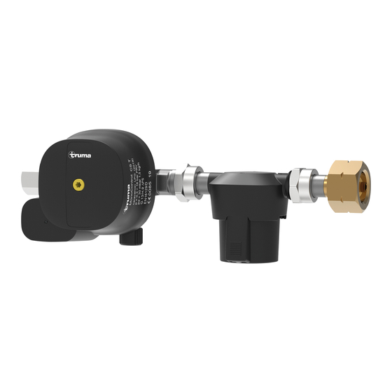
Gasdruckregler, Gasfilter und Adapter Es darf nur geeignetes Werkzeug verwendet werden. Keine Rohrzange verwenden! montieren Der Gasdruckregler sollte so montiert werden, dass das Typenschild lesbar, der gelbe Resetknopf (Rücksetzung des Crashsensors) erkennbar und gut erreichbar ist. Bild 3 1 Gasrohr 30 mbar 10 mm 2 Schneidringverschraubung 3 MonoControl CS T 4 Dichtring... -
Seite 7: Einheit In Den Armaturenkasten Montieren
– In die Überwurfmutter vom Gasfilter (Bild 3 - 5) einen Dich- – Gasdruckregler und Gasfilter so ausrichten, dass beide in tring (Bild 3 - 4) auf den Bund aufstecken. senkrechter Position zum Boden stehen. (Bild 6) – MonoControl CS T (Bild 3 - 3) und Gasfilter (Bild 3 - 5) hand- fest zusammenschrauben. –... -
Seite 8: Gasrohr Montieren
Schlüsselflächen gegen halten. apter (Bild 3 - 7) mit einem Schraubenschlüssel (SW 23) mit 13,5 - 16,5 Nm anziehen. Für 30 mbar-Anlagen mit 8 mm Gasrohr bietet Truma eine gerade Reduzierverschraubung RST 10 x RVS 8 mm – Die Überwurfmutter zwischen MonoControl CS T (Bild 3 - 3) als Zubehör an. -
Seite 9: Technische Daten
Abmessungen – Anschließend müssen alle Funktionen gemäß der Ge- brauchsanweisung geprüft werden. – Die Gebrauchsanweisungen dem Betreiber aushändigen. Technische Daten W21,8 x 1/4 LH M20 x 1,5 Gasart Flüssiggas LPG (Propan / Butan) Betriebsdruck 0,3 bis 16 bar Maximaler Durchfluss Mg = 1,5 kg/h Temperaturbereich -20 °C bis +50 °C... - Seite 10 Alle Maße im mm Technische Änderungen vorbehalten!
-
Seite 11: Safety Instructions
................. 15 Install the unit in the fitting box .......... 16 Installing the gas pipe ............17 Use only original Truma spare parts and accessories. Final work ................17 Technical specifications ..........18 Explosion hazard! Residual gases can escape when Dimensions ................. -
Seite 12: Abbreviations
Abbreviations Variants AF = Width across flats (in mm) The packaging for the MonoControl CS T Set contains the LH = Left-hand thread operating instructions for the MonoControl CS. These instruc- CS = Crash sensor tions apply also to MonoControl CS T. The only differences = Tank (gas tank) between the two gas pressure regulators are the connection bracket for the gas pipe and a fastening bracket. -
Seite 13: Intended Use
Intended use Improper use The MonoControl CS T Set consists of a MonoControl CS T, All other uses not listed under proper use are improper and a gas filter and an adapter for gas tanks. therefore prohibited. The adapter is intended for direct connection to the tank with- This applies for example to installation and operation in: drawal valve with a male thread W 21.8 x 1/14”... -
Seite 14: Installation Instructions
- Dynamic load Only competent and trained staff (experts) are permitted - Pipe connections to install and repair the Truma product and to carry out the - Fixing function test, at the same time observing the installation and - Installation of LP gas tanks operating instructions and the currently recognised technical regulations. -
Seite 15: Installing The Gas Pressure Regulator, Gas Filter And Adapter
Installing the gas pressure regulator, gas filter Use only appropriate tools. Do not use a pipe wrench. and adapter The gas pressure regulator should be installed so that the type plate is legible and the yellow reset button (crash sensor reset) is visible and easy to access. -
Seite 16: Install The Unit In The Fitting Box
– In the union nut of the gas filter (Figure 3 - 5), place a sealing – Align the gas pressure regulator and the gas filter so that ring (Figure 3 - 4) on the collar. both are vertical to the floor. (Figure 6) – Screw the MonoControl CS T (Figure 3 - 3) and gas filter (Figure 3 - 5) together finger tight. -
Seite 17: Installing The Gas Pipe
(AF 20) to brace against the flats. – Use a spanner (AF 23) to tighten the union nut between the Truma can supply a straight reducer union RST 10 x RVS 8 gas filter (Figure 3 - 5) and the adapter (Figure 3 - 7) with as an accessory for 30 mbar systems with 8 mm gas pipes. -
Seite 18: Technical Specifications
Dimensions – All functions must then be tested in accordance with the operating instructions. – The operating instructions must be given to the operator. Technical specifications W21.8 x 1/4 LH M20 x 1.5 Gas type Liquid gas LPG (propane / butane) Operating pressure 0.3 to 16 bar Maximum flow Mg = 1.5 kg/h... - Seite 19 All dimensions in mm Subject to technical changes.
-
Seite 20: Informations Concernant La Sécurité
Monter le tube de gaz ............26 Travaux finaux ..............26 Utiliser uniquement des pièces de rechange et des Caractéristiques techniques .......... 27 accessoires d’origine Truma. Dimensions ................. 27 Risque d’explosion. Des gaz résiduels peuvent s’échap- per lors du changement du coussin filtrant. Feux et flammes nues interdits, défense de fumer. -
Seite 21: Abréviations
Abréviations Variantes Ø = ouverture de clé (indication en mm) Le mode d’emploi du MonoControl CS est joint à l’emballage LH = filet à gauche (en anglais : Left-Hand Thread) du kit MonoControl CS T. Ces instructions s’appliquent aussi CS = capteur de choc (en anglais : Crash Sensor) au MonoControl CS T. -
Seite 22: Utilisation
Utilisation Utilisation non conforme Le kit MonoControl CS T se compose d’un MonoControl CS T, Toutes les utilisations autres non mentionnées dans l’utilisa- d’un filtre à gaz et d’un adaptateur pour réservoirs à gaz. tion conforme sont non admissibles et donc interdites. L’adaptateur est prévu pour le raccordement direct à la sou- Cela s’applique par exemple au montage et au fonctionne- pape de prélèvement de réservoir avec un raccordement à... -
Seite 23: Instructions De Montage
– Les normes suivantes doivent entre autres être respectées : Seul un personnel spécialisé et formé est autorisé à monter DIN EN 1949 les produits Truma, à les réparer et à en vérifier le fonction- - Sollicitation dynamique nement en respectant les instructions de montage et le - Connexions de tuyaux mode d’emploi ainsi que les règles techniques reconnues en... -
Seite 24: Monter Le Détendeur À Gaz, Le Filtre À Gaz Et L'adaptateur
Monter le détendeur à gaz, le filtre à gaz et Utiliser seulement des outils appropriés. Ne pas utiliser de serre-tubes. l’adaptateur Monter le détendeur à gaz de telle sorte que la plaque si- gnalétique soit lisible et le bouton de réinitialisation jaune (réinitialisation du capteur de choc) reconnaissable et bien accessible. -
Seite 25: Monter L'unité Dans Le Boîtier À Robinets
– Enfoncer un joint d’étanchéité (figure 3 - 4) sur le collet de – Orienter le détendeur à gaz et le filtre à gaz de sorte que l’écrou chapeau du filtre à gaz (figure 3 - 5). les deux se trouvent en position verticale par rapport au sol. (figure 6) –... -
Seite 26: Monter Le Tube De Gaz
Pour les installations de 30 mbar avec un tube de gaz de – Serrer à 13,5 - 16,5 Nm l’écrou chapeau entre 8 mm, Truma propose en tant qu’accessoire un raccord le MonoControl CS T (figure 3 - 3) et le filtre à gaz de réduction droit RST 10 x RVS 8 mm. -
Seite 27: Caractéristiques Techniques
Dimensions – Ensuite, vérifier toutes les fonctions conformément au mode d’emploi. – Remettre le mode d’emploi à l’exploitant. Caractéristiques techniques W21,8 x 1/4 LH M20 x 1,5 Type de gaz Gaz liquéfié GPL (propane / butane) Pression de service 0,3 - 16 bar Débit maximum Débit = 1,5 kg/h Plage de températures... - Seite 28 Toutes les dimensions sont exprimées en mm Sous réserve de modifications techniques.
-
Seite 29: Avvertenze Di Sicurezza
Montaggio del gruppo nella scatola di protezione valvolame .. 34 Impiegare esclusivamente parti di ricambio e accessori Montaggio del tubo del gas ..........35 originali Truma. Lavori conclusivi ..............35 Specifiche tecniche ............36 Pericolo di esplosione! Nel sostituire gli elementi filtranti Dimensioni ................ -
Seite 30: Abbreviazioni
Abbreviazioni Varianti SW = apertura di chiave (misura in mm) La confezione del kit MonoControl CS T contiene anche le LH = passo sinistro (inglese: left-hand thread) istruzioni per l’uso del MonoControl CS. Queste istruzioni CS = crash sensor sono valide anche per il MonoControl CS T. I due regolatori di = serbatoio (del gas) pressione del gas si differenziano per l’attacco ad angolo per il tubo del gas e l’angolare di fissaggio. -
Seite 31: Destinazione D'uso
Destinazione d’uso Uso non conforme Il kit MonoControl CS T è composto da un MonoControl CS T, Qualsiasi uso diverso da quanto indicato nel paragrafo un filtro gas e un adattatore per serbatoi del gas. «Uso conforme» è da considerarsi non conforme e quindi non L’adattatore si collega direttamente alla valvola di prelievo del consentito. -
Seite 32: Istruzioni Di Montaggio
- raccordi dei tubi ne professionale, delle conoscenze e delle esperienze acqui- - fissaggio site con i prodotti Truma e le norme pertinenti, sono in grado - installazione di serbatoi di gas liquido di eseguire correttamente i lavori necessari e di individuare possibili pericoli. -
Seite 33: Montaggio Del Regolatore Di Pressione Del Gas, Del Filtro Gas E Dell'adattatore
Montaggio del regolatore di pressione del gas, Utilizzare esclusivamente un utensile adatto. Non utilizzare pinze per tubi! del filtro gas e dell’adattatore Montare il regolatore di pressione del gas in modo che la tar- ga dati sia leggibile e il pulsante di reset giallo (ripristino del crash sensor) sia riconoscibile e facilmente accessibile. -
Seite 34: Montaggio Del Gruppo Nella Scatola Di Protezione Valvolame
– Inserire un anello di tenuta (figura 3 - 4) sul collare del dado – Disporre il regolatore di pressione e il filtro gas in verticale per raccordi del filtro gas (figura 3 - 5). verso il pavimento (figura 6). – Avvitare insieme a mano MonoControl CS T (figura 3 - 3) e il filtro gas (figura 3 - 5). -
Seite 35: Montaggio Del Tubo Del Gas
– Serrare il dado per raccordi tra il filtro gas (figura 3 - 5) e l’adattatore (figura 3 - 7) con una chiave per dadi da 23 a Per impianti a 30 mbar con tubo del gas da 8 mm Truma 13,5 - 16,5 Nm. mette a disposizione come accessorio una riduzione diritta RST 10 x RVS 8 mm. -
Seite 36: Specifiche Tecniche
Dimensioni – Infine verificare tutte le funzioni consultando le istruzioni per l’uso. – Le istruzioni per l’uso devono essere consegnate all’utente. Specifiche tecniche W21,8 x 1/4 LH M20 x 1,5 Tipo di gas Gas liquido GPL (propano / butano) Pressione di esercizio da 0,3 a 16 bar Portata massima Mg = 1,5 kg/h... - Seite 37 Tutte le dimensioni sono espresse in mm Salvo modifiche tecniche!
- Seite 40 In order to avoid delays, please have the unit model and serial number ready (see type plate). Veuillez vous adresser au centre de SAV Truma ou à un de nos partenaires de SAV agréés en cas de dysfonctionnements (voir www.truma.com). Pour un traitement rapide de votre demande, veuillez tenir prêts le type d’appareil et le numéro...