Inhaltsverzeichnis
Werbung
Verfügbare Sprachen
Verfügbare Sprachen
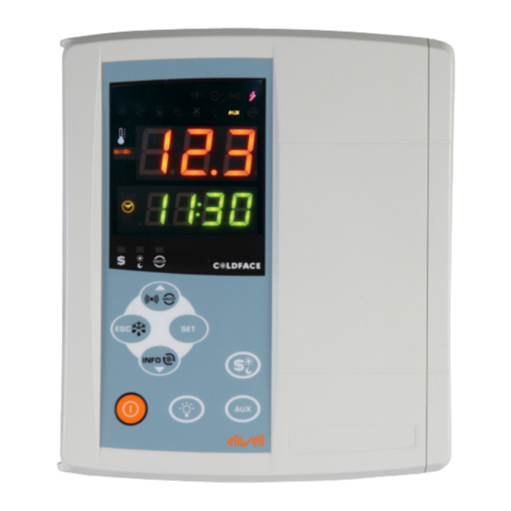
EWRC300/500LX
Controllers for cold rooms for on-board installation
Controllori per celle refrigerate per installazione a bordo cella
Controles para cámaras refrigeradas para montaje a bordo de la cámara
Kühlzellenregler für Installation in Kühlzelle
Contrôleurs pour chambres de réfrigération avec installation à bord de la chambre
Контроллеры холодильных камер в щитовом исполнении
Werbung
Inhaltsverzeichnis
Fehlerbehebung

Verwandte Anleitungen für Eliwell Coldface EWRC300LX


Inhaltszusammenfassung für Eliwell Coldface EWRC300LX
- Seite 1 EWRC300/500LX Controllers for cold rooms for on-board installation Controllori per celle refrigerate per installazione a bordo cella Controles para cámaras refrigeradas para montaje a bordo de la cámara Kühlzellenregler für Installation in Kühlzelle Contrôleurs pour chambres de réfrigération avec installation à bord de la chambre Контроллеры...
-
Seite 2: Mechanical Installation
The box allows for installation of a power contactor or a disconnecting switch with door lock. This summary document contains basic information about the standard models EWRC300/500LX. For further information and different configurations, refer to the complete user manual p/n 9MA10023 which can be downloaded free of charge from the www.eliwell.it website. NAVIGATION DIAGRAM display display SetPoint &... -
Seite 3: Electrical Connections
ELECTRICAL CONNECTIONS Output relay (default settings) To switch between NTC/PTC probe types use • OUT1 relay 1 = Compressor (or liquid line parameter H00. SWITCH OFF AND RESTART valve) THE INSTRUMENT after making the change • OUT2 relay 2 = Defrost •... - Seite 4 DISPLAYS UPPER DISPLAY • 3 digits and - sign: View: • Operating value • parameters label • alarms, functions 11 10 9 If the upper display is blinking UPPER DISPLAY it means that the value of the lower display can be modified LOWER DISPLAY LOWER DISPLAY •...
-
Seite 5: User Interface
KEYS press and release press and hold for about 3 seconds Notes •Alarms Menu (always visible) HACCP alarms Battery p UP • Scroll only in HACCP models and when • Increase values alarms present • Exit • Manual defrost • Functions menu •... - Seite 6 LITE PARAMETER TABLE This section describes the most useful parameters, which are contained in the 'Lite' folder. For a description of all User (USr) and Installer (Ins) parameters, see the user manual. Note: the 'Lite' folder parameters are NOT divided into subfolders and are always visible (no access password is required).
- Seite 7 THE INSTRUMENT ENABLES MODIFICATION OF OTHER PARAMETERS DIVIDED INTO USER LEVEL (USr) and INSTALLER LEVEL (InS) How to modify other parameters Installer (InS) level access - User level access is similar: Procedure applies only to more advanced applications. In this case the parameters are arranged in folders (Compressor / Defrost / Fans etc) 1) Press and hold the SET key for 3 seconds until the display shows PAr / Lite 2) Use the UP &...
-
Seite 8: Alarms And Troubleshooting
ALARM RELAY - EWRC500LX only Relay OUT4 is configured as alarm relay and is activated in the case of alarms, according to delays and parameter settings* LIGHT - EWRC500LX only The light is activated by pressing and holding the LIGHT key (G) Since digital input D.I. -
Seite 9: Technical Support
*E1 - E2: If simultaneous they will be shown alternately on the display at a frequency of 2 seconds TECHNICAL SUPPORT Please have the following information available when contacting Eliwell Technical Support: • IdF firmware version (e.g. 390) • rEL firmware version release (e.g. 1,2,...) •... -
Seite 10: Technical Data
TECHNICAL DATA DESCRIPTION Front panel IP54 Container Bayblend FR 110 Dimensions front 210x245mm, depth 90mm Mounting wall mounting (centre distance of holes A-B 181.0 mm; holes C-D 196.5 mm. See Mechanical Installation paragraph) Connections • removable screw terminals for serial port RS-485, digital and analogue inputs •... - Seite 11 Eliwell. Every care has been taken in preparing this document; nevertheless Eliwell declines any liability due to its use. The same applies to any person or company involved in the creation and preparation of this document. Eliwell reserves the right to make aesthetic or functional changes at any time without notice.
-
Seite 12: Montaggio Meccanico
Il box permette di installare un contattore di potenza o un sezionatore con blocco porta. Questo documento, in formato ridotto, contiene le informazioni base dei modelli standard EWRC300/ 500LX. Per approfondimenti e configurazioni diverse, fare riferimento al manuale d’uso completo cod. 9MA00023 scaricabile gratuitamente dal sito www.eliwell.it SCHEMA NAVIGAZIONE visualizza... -
Seite 13: Connessioni Elettriche
CONNESSIONI ELETTRICHE Relé di uscita (impostazioni di default) Per cambiare tipo sonde NTC/PTC utilizzare • OUT1 relé 1 = Compressore parametro H00. SPEGNERE E RIACCENDERE LO (o valvola linea liquido) STRUMENTO dopo la modifica • OUT2 relé 2 = Sbrinamento •... - Seite 14 DISPLAY DISPLAY SUPERIORE • 3 cifre più il segno - : Visualizza: • Valore operativo • label parametri • allarmi, funzioni 11 10 9 se Display Superiore lampeg- DISPLAY SUPERIORE giante indica che il valore del Display Inferiore può essere modificato DISPLAY INFERIORE DISPLAY INFERIORE...
-
Seite 15: Interfaccia Utente
TASTI TASTO premere e rilasciare premere per 3 secondi circa Note • Menu Allarmi (sempre visibile) Allarmi HACCP p UP • Scorrimento solo nei modelli previsti • Aumento valori e se presenti • Uscita • Sbrinamento manuale • Menu Funzioni •... - Seite 16 TABELLA PARAMETRI LITE In questa sezione sono descritti i parametri di maggior utilizzo che si trovano all’interno della cartella ‘Lite’ . Per la descrizione di tutti gli altri para- metri Utente (USr) ed Installatore (Ins) fare riferimento al manuale d’uso. NOTA: i parametri della cartella ‘Lite’ NON sono suddivisi in sottocartelle e sono sempre visibili (non è...
- Seite 17 LO STRUMENTO PERMETTE DI MODIFICARE ALTRI PARAMETRI DIVISI IN LIVELLO UTENTE (USr) ed INSTALLATORE (InS) Come modificare gli altri Parametri Accesso al Livello Installatore (InS) - il livello Usr è analogo: Procedura valida solo per le applicazioni più avanzate. In questo caso i parametri sono predisposti in cartelle (Compressore / Sbrinamento / Ventole ecc) 1) Premere e mantenere premuto il tasto SET per 3 secondi fino a quando il display non visualizza PAr / Lite...
- Seite 18 RELÉ ALLARME - solo EWRC500LX Il relè OUT4 è configurato come relè di allarme e si attiva nel caso di allarme ove previsto, in funzi- one dei ritardi ed impostazioni da parametro* LUCE - solo EWRC500LX La luce si attiva tramite pressione prolungata del tasto LUCE (G) Poichè...
-
Seite 19: Supporto Tecnico
TABELLA ALLARMI In questa sezione sono evidenziati gli allarmi legati alla configurazione standard dello strumento. Per la descrizione di allarmi legati a configu- razioni personalizzate consultare il manuale d’uso oppure contattare il Supporto Tecnico Eliwell Label Causa Effetti Risoluzione problema •... -
Seite 20: Dati Tecnici
DATI TECNICI DESCRIZIONE Protezione frontale IP54 Contenitore Bayblend FR 110 Dimensioni frontale 210x245mm profondità 90mm Montaggio a parete (interasse fori A-B 181,0 mm; fori C-D 196,5 mm. Vedi paragrafo Montaggio Meccanico) Connessioni • morsetti sconnettibili a vite per seriale RS-485, ingressi digitali e ingressi analogici •... - Seite 21 • installazione/uso in quadri non conformi alle norme e disposizioni di legge vigenti. DECLINAZIONE DI RESPONSABILITA’ La presente pubblicazione é di esclusiva proprietà della Eliwell la quale pone il divieto assoluto di riproduzione e divulgazione se non espressamente autorizzata dalla Eliwell stessa. Ogni cura é stata posta nella realizzazione di questo documento;...
-
Seite 22: Montaje Mecánico
Este documento, en formato reducido, contiene la información básica de los modelos estándar EWRC300/500LX. Para mayor detalle y configuraciones distintas, consulte el manual de uso completo 9MA30023 que puede descargar gratuitamente desde nuestra web wwww.eliwell.it ESQUEMA DE NAVEGACIÓN SetPoint & Sondas SetPoint &... -
Seite 23: Conexiones Eléctricas
CONEXIONES ELÉCTRICAS Relés de salida (configuración por defecto) Para cambiar el tipo de sonda NTC/PTC utilice el • OUT1 relé 1 = Compresor parámetro H00. APAGUE Y VUELVA A ENCEN- (o válvula línea de líquido) DER EL INSTRUMENTO tras la modificación. •... - Seite 24 DISPLAY DISPLAY SUPERIOR • 3 dígitos più signo - : Visualiza: • Valor operativo • etiqueta de los parámetros • alarmas, funciones 11 10 9 si el Display Superior parpadea DISPLAY SUPERIOR indica que el valor del Display Inferior puede ser modificado DISPLAY INFERIOR DISPLAY INFERIOR •...
-
Seite 25: Interfaz De Usuario
TECLAS Nº TECLA pulsar y soltar pulsar unos 3 segundos aprox. Notas • Menú de Alarmas (siempre visibile) Alarmas HACCP p UP • Desplazamiento solo nei modelli previsti • Aumento de valores e se presenti • Salida • Desescarche manual •... - Seite 26 TABLA DE PARÁMETROS “LITE” En esta sección se describen los parámetros de mayor uso que se encuentran dentro de la carpeta “Lite”. Para la descripción de los restantes parámetros del Usuario (USr) e Instalador (Ins) consulte el manual de uso. NOTA: los parámetros de la carpeta “Lite” NO se hayan subdivididos en subcarpetas y son siempre visibles (no hay contraseña de acceso).
- Seite 27 EL INSTRUMENTO PERMITE MODIFICAR OTROS PARÁMETROS DIVIDIDOS EN NIVEL DE USUA- RIO (USr) e INSTALADOR (InS) Cómo modificar los otros parámetros Acceso a nivel Instalador (InS) - el nivel Usr es análogo: Procedimiento válido solo para las aplicaciones más avanzadas. En este caso los parámetros se en- cuentran en carpetas (Compresor / Desescarche / Ventiladores etc).
- Seite 28 RELÉ de Alarma - solo EWRC500LX El relé OUT4 está configurado como relé de alarma y se activa en caso de alarma cuando sea necesa- rio, en función de los retardos y configuraciones de los parámetros* LUZ - solo EWRC500LX La luz se activa manteniendo pulsada la tecla LUZ (G) Como la entrada digital D.I.
- Seite 29 TABLA DE ALARMAS En esta sección se muestran las alarmas referidas a la configuración estándar del instrumento. Para la descripción de alarmas referidas a confi- guraciones personalizadas consulte el manual de uso o contacte con el Soporte Técnico de Eliwell. Causa Efectos Solución del problema...
-
Seite 30: Datos Técnicos
DATOS TÉCNICOS DESCRIPCIÓN Protección frontal IP54 Caja Bayblend FR 110 Dimensiones frontal 210x245mm profundidad 90mm Montaje en pared (eje entre agujeros A-B 181,0 mm; agujeros C-D 196,5 mm. Ver apartado Montaje Mecánico) Conexiones • bornes extraíbles de tornillo para serial RS-485, entradas digitales y entradas analógicas •... - Seite 31 La presente publicación es de propiedad exclusiva de Eliwell, que prohíbe de manera absoluta la reproducción y divulgación si no ha sido expresamente autorizada por la misma Eliwell. Se ha puesto el mayor cuidado en la realización del presente documento; aun así Eliwell no asume responsabili- dad alguna que se derive del uso del mismo.
-
Seite 32: Mechanischer Einbau
Die Box ermöglicht die Installation eines Leistungsschützes oder eines Trennschalters mit Türverriegelung. Dieses in Kurzfassung angefertigte Dokument enthält die wesentlichen Informationen der EWRC300/500LX Stan- dardmodelle. Für weitere Informationen zur Konfiguration steht unsere Bedienungsanleitung code: 9MA50023 zum freien download auf der website www.eliwell.it zur Verfügung. NAVIGATIONSPLAN Sollwert & Fühler... -
Seite 33: Elektrische Anschlüsse
ELEKTRISCHE ANSCHLÜSSE Ausgangsrelais (Standardeinstellungen) Zur Änderung des Fühlertyps NTC/PTC den Pa- • OUT1 Relais 1 = Verdichter (oder Ventil der rameter H00 verwenden. Nach der Änderung Flüssigkeitsleitung) DAS GERÄT AUS- UND WIEDER EINSCHALTEN • OUT2 Relais 2 = Abtauen • OUT3 Relais 3 = Verdampfergebläse Digitaleingänge (Standardeinstellungen) •... - Seite 34 DISPLAY OBERE DISPLAYANZEIGE • 3 Stellen mit - Vorzeichen: Anzeigen: • Betriebswert • Label Parameter • Alarme, Funktionen 11 10 9 OBERE bei Blinken der oberen Dis- DISPLAYANZEIGE playanzeige kann der an der unteren Displayanzeige eingeblendete Wert geändert werden UNTERE DISPLAYANZEIGE UNTERE DISPLAYANZEIGE •...
-
Seite 35: Benutzeroberfläche
TASTEN TASTE drücken und loslassen ca. 3 Sekunden lang drücken Anmerkungen • Menü Alarme (stets sichtbar)* HACCP-Alarme p UP • Durchlaufen nur bei HACCP Modellen • Werte steigern und aktuellen Alarme • Beenden • Manuelles Abtauen • Menü Funktionen • Zum Hauptmenü •... - Seite 36 PARAMETERTABELLE LITE Dieser Abschnitt beschreibt die meistbenutzten Parameter in der Registerkarte ‘Lite’ . Für die Beschreibung aller anderen Benutzer- (USr) und Installateur-Parameter (Ins) wird auf die Bedienungsanleitung verwiesen. HINWEIS: die Parameter der Registerkarte ‘Lite’ sind NICHT in Unter-Registerkarten organisiert und stets sichtbar (für den Zugriff ist kein Passwort vorgesehen). Die gleichen Parameter sind auch in den entsprechenden Registerkarten ‘Verdichter’...
-
Seite 37: Betrieb Mit Standardkonfiguration
MIT DEM GERÄT KÖNNEN ANDERE IN BENUTZER- (USr) und INSTALLATEUR-EBENE (InS) UN- TERTEILTE PARAMETER GEÄNDERT WERDEN Änderung der anderen Parameter Abrufen der Installateur-Ebene (InS) - sinngemäß für Benutzerebene (Usr): Verfahren nur für erweiterte Anwendungen gültig. In diesem Fall sind die Parameter in Register- karten (Verdichter / Abtauung / Gebläse usw.) organisiert 1) Taste SET 3 Sekunden lang drücken, bis am Display PAr / Lite erscheint 2) Mit den Tasten UP &... -
Seite 38: Alarme Und Problembehebung
ALARMRELAIS - nur EWRC500LX Das als Alarmrelais konfigurierte Relais OUT4 aktiviert sich bei Alarmen, sofern vorgesehen, auf der Grundlager parameterseitiger Verzögerungen und Einstellungen* BELEUCHTUNG - nur EWRC500LX Die Beleuchtung wird durch längeres Drücken der Taste BELEUCHTUNG (G) aktiviert Durch Konfiguration des Digitaleingangs D.I. 1 als Türmikroschalter aktiviert sich das Relais OUT5 (Be- leuchtung) beim Öffnen der Tür. - Seite 39 ALARMTABELLE In diesem Abschnitt sind die Alarme im Zusammenhang mit der Standardkonfiguration des Geräts aufgelistet. Für die Alarmbeschreibung bei personalisierten Konfigurationen die Bedienungsanleitung einsehen oder den technischen Service Eliwell verständigen Label Ursache Auswirkungen Problembehebung • Anzeige des Labels E1 Zellenfühler Pb1 defekt •...
-
Seite 40: Technische Daten
TECHNISCHE DATEN BESCHREIBUNG Schutzart Frontblende IP54 Gehäuse Bayblend FR 110 Abmessungen Frontseite 210x245mm, Tiefe 90mm Einbau Wandmontage (Bohrungsabstand A-B 181,0 mm; C-D 196,5 mm. Siehe Absatz Mechanischer Einbau) Anschlüsse • Trennbare Schraubklemmen für seriellen Anschluss RS-485, Digitaleingänge und Analogeingänge • Trennbare Schraubklemmen oder FASTON für Stromversorgung und Digitalausgänge (siehe Schaltpläne) Aufnahme für Trennschalter Türverriegelung, Schütz usw. -
Seite 41: Nutzungsbedingungen - Zulässiger Gebrauch
ISO14001 Eliwell ist seit etlichen Jahren nach ISO 14000 zertifiziert und garantiert somit die opti- mierte Anwendung des Umweltmanagementsystems. Als Mitglied des Italienischen Ausschusses für Elektrotechnik ist Eliwell aktiv an der Ent- wicklung des Normungsrahmens beteiligt. Die Eliwell Entwicklungstecniker verfügen dadurch über ausgereifte Ausbildungskompe- tenzen in den Bereichen: •... -
Seite 42: Montage Mécanique
Ce document, en format réduit, contient les informations de base des modèles standards EWRC300/500LX. Pour tout approfondissement et pour toute autre configuration, se référer au ma- nuel d’utilisation complet cod. 9MA20023 téléchargeable gratuitement depuis le site www.eliwell.it SCHÉMA NAVIGATION Visualisation Point de consigne &... -
Seite 43: Branchements Électriques
BRANCHEMENTS ÉLECTRIQUES Relais de sortie (configurations par défaut) Pour changer le type de sondes NTC/PTC, se ser- • OUT1 relais 1 = Compresseur (ou vanne ligne vir du paramètre H00. ÉTEINDRE ET RALLUMER liquide) L’INSTRUMENT après la modification. • OUT2 relais 2 = Dégivrage •... - Seite 44 AFFICHEUR AFFICHEUR SUPÉRIEUR • 3 chiffres plus le signe - : Visualisation : • valeur opérationnelle • étiquette paramètres • alarmes, fonctions 11 10 9 un Afficheur Supérieur qui cli- AFFICHEUR SUPÉRIEUR gnote indique que la valeur de l’Afficheur Inférieur peut être modifiée AFFICHEUR INFÉRIEUR AFFICHEUR INFÉRIEUR...
-
Seite 45: Interface Utilisateur
TOUCHES N° TOUCHE Appuyer et relâcher Appuyer pendant 3 secondes environ Remarques • Menu Alarmes (toujours visible) Alarmes HACCP p UP • Défilement uniquement sur les modèles pré- • Augmentation valeurs vus et si présentes • Sortie • Dégivrage manuel •... - Seite 46 TABLEAU DES PARAMÈTRES LITE Cette section décrit les paramètres les plus utilisés du répertoire « Lite ». Pour la description de tous les autres paramètres Utilisateur (USr) et Installateur (Ins), se référer au manuel d’utilisation. REMARQUE : les paramètres du répertoire « Lite » NE sont PAS subdivisés en sous-répertoires et sont toujours visibles (aucun mot de passe d’accès n’...
- Seite 47 L’INSTRUMENT PERMET DE MODIFIER D’AUTRES PARAMÈTRES DIVISÉS EN NIVEAU UTILISA- TEUR (USr) et INSTALLATEUR (InS) Comment modifier les autres Paramètres Accès au Niveau Installateur (InS) - le niveau Usr est analogue : Procédure valable uniquement pour les applications les plus avancées. Dans ce cas, les paramètres sont présentés dans des répertoires (Compresseur / Dégivrage / Ventilateurs, etc.) 1) Appuyer sur la touche SET pendant 3 secondes jusqu’à...
- Seite 48 RELAIS ALARME - uniquement EWRC500LX Le relais OUT4 est configuré comme relais d’alarme et son activation se produit en cas d’éventuelle alarme, en fonction des retards et des configurations paramétrables* LUMIÈRE - uniquement EWRC500LX Pour activer la lumière, appuyer de façon prolongée sur la touche LUMIÈRE (G) Étant donné...
-
Seite 49: Support Technique
TABLEAU DES ALARMES Cette section présente les alarmes liées à la configuration standard de l’instrument. Pour la description d’alarmes liées à des configurations personnalisées, consulter le manuel d’utilisation ou bien contacter le Support Technique Eliwell Étiquette Cause Effets Résolution problème •... -
Seite 50: Données Techniques
DONNÉES TECHNIQUES DESCRIPTION Protection frontale IP54 Boîtier Bayblend FR 110 Dimensions frontal 210x245 mm, profondeur 90 mm Montage mural (entraxe trous A-B 181,0 mm ; trous C-D 196,5 mm. Voir paragraphe Montage Mécanique) Connexions • bornes déconnectables à vis pour série RS-485, entrées numériques et entrées analogiques •... -
Seite 51: Dégagement De Responsabilité
Eliwell n’est nullement responsable en ce qui concerne son utilisation. Il en va de même pour toute personne ou société impliquée dans la création et la rédaction du présent manuel. Eliwell se réserve le droit d’ap- porter toute modification, esthétique ou fonctionnelle, sans aucun préavis et à n’importe quel moment. -
Seite 52: Механическая Установка
ВСТУПЛЕНИЕ Контроллеры EWRC300/500LX серии Coldface регулируют температуру в статических или вентилируемых холодильных камерах. Прибор может использоваться в средне- и низкотемпературных камерах и может управлять двумя испарителями и конденсатором. Контроллеры имеют 3 или 5 конфигурируемых реле в зависимости от модели, 2 цифровых входа... -
Seite 53: Электрические Подключения
ЭЛЕКТРИЧЕСКИЕ ПОДКЛЮЧЕНИЯ Выходные реле (исходные настройки) Для смены типа датчика NTC/PTC • OUT1 реле 1 = Компрессор/Соленоид используйте параметр H00. Затем • OUT2 реле 2 = Разморозка ПЕРЕДЕРНИТЕ ПИТАНИЯ ПРИБОРА! • OUT3 реле 3 = Вентилятор испарителя • OUT4 реле 4 = Авария (только EWRC500LX) Цифровые... - Seite 54 ДИСПЛЕЙ ВЕРХНЯЯ СТРОКА • 3 цифры и знак «-» Просмотр: • Рабочего значения • Меток параметров • Аварий, Функций Если верхняя строка мигает, то значение нижней строки можно менять НИЖНЯЯ СТРОКА • 4 цифры Просмотр: • Значений параметров • Значений датчиков •...
-
Seite 55: Интерфейс Пользователя
КНОПКИ № КНОПКИ Короткое нажатие Удержание не менее 3 секунд Примечания • Меню Аварий (всегда видимо) Аварии HACCP только в моделях с HACCP и ▲ВВЕРХ • Прокрутка вверх когда имеются аварии • Увеличение редактируемого значения • Возврат на один уровень меню вверх •... - Seite 56 ТАБЛИЦА ПАРАМЕТРОВ СОКРАЩЕННОГО НАБОРА (LITE) В данном разделе описаны наиболее используемые параметры, включенныеы в папку «Lite». Описание всех параметров уровней Пользователя (USr) и Инсталлятора (Ins) дано в полном Руководстве пользователя. Помните, что параметры папки «Lite» НЕ разделяются на подпапки и ВСЕГДА доступны (нет пароля). Они же входят...
- Seite 57 РЕДАКТИРОВАНИЕ ПАРАМЕТРОВ УРОВНЕЙ ПОЛЬЗОВАТЕЛЯ (USr) И ИНСТАЛЯТОРА (InS) Как изменять остальные параметры Доступ к параметрам уровней Пользователя (USr) и Инсталлятора (InS) аналогичен: Процедура необходима в установках с более сложными настройками (конфигурацией). Параметры уровней доступа подразделяются на папки (Компрессор / Разморозка / …) 1) Удерживайте...
- Seite 58 РЕЛЕ АВАРИИ – только в EWRC500LX Релейный выход OUT4 сконфигурирован как реле Аварии и активизируется при регистрации аварии с учетом задержек и настроек параметров* РЕЛЕ СВЕТА - только в EWRC500LX Свет включается и выключается удержанием кнопки «СВЕТ» (G) Так как цифровой вход D.I. 1 сконфигурирован как реле двери, свет (OUT5) включается и при открытии...
-
Seite 59: Техническая Поддержка
использованием часов RTC • обратитесь за технической разряжена становятся недоступными поддержкой в Eliwell ВСЕ АВАРИИ • Индикатор аварии непрерывно горит • Зуммер и реле аварии (если есть выход OUT4) активизируются кроме случая аварии Разморозки Ad2 • Для принятия аварии нажмите любую кнопку, индикатор аварии начнет мигать, зуммер выключится, но реле... -
Seite 60: Технические Данные
ТЕХНИЧЕСКИЕ ДАННЫЕ ОПИСАНИЕ Лицевая панель IP54 Корпус пластик Bayblend FR 110 Размеры лицевая панель 210x245 мм, глубина 90 мм на стену (расстояние между центрами отверстий A-B 181,0 мм mm; отверстий C-D Установка 196,5 мм. Смотри раздел механической установки) • съемные винтовые клеммы порта RS-485, цифровых и аналоговых входов •... - Seite 61 ISO14001 Eliwell в течении нескольких лет имеет сертификат ISO 14000, гарантируя таким образом соблюдение Правил Экологического Контроля. Eliwell является членом Итальянской ассоциации электрических инженеров (Comitato Elettrotecnico Italiano) и вносит соответствующие взносы. Это обеспечивает преимущество технических разработок Eliwell в сферах: • электрической безопасности...
- Seite 64 +39 0437 986 200 (other countries) saleseliwell@invensyscontrols.com Technical helpline: +39 0437 986 300 E-mail techsuppeliwell@invensyscontrols.com www.eliwell.it 9IS64126 - EN - IT - ES - DE - FR - RU - rel. 06/09 © Eliwell Controls s.r.l. 2009 All rights reserved.