
Verwandte Anleitungen für PIKO Navigator


Inhaltszusammenfassung für PIKO Navigator
- Seite 1 Navigator Bedienungsanleitung Operation Manual 35017-90-7000_2019_cover.indd 3 05.06.19 10:07...
- Seite 2 PIKO Navigator 35017-90-7000_2019_cover.indd 4 05.06.19 10:07...
- Seite 3 Navigator Bedienungsanleitung 06/2019_ab Software Version 2.01p 35017-90-7000_2019_p1-38.indd 1 05.06.19 10:02...
-
Seite 4: Inhaltsverzeichnis
Inbetriebnahme ....................5 Anschluss .....................5 2.1.1 Ein und Ausschalten ..................5 2.1.2 Eingabe der Lokadresse und erster Fahrbetrieb ..........6 2.1.2.1 Fahrbetrieb mit dem PIKO Analogfahrregler (35002) ........6 2.1.3 Informationen über Funk ................6 2.1.4 Betrieb an Fremdzentralen ................6 2.1.5 Eingeschränkte Funktionen an MZS III ............6 Menü-Übersichtsdiagramm ................7... - Seite 5 PoM - Program on main / Programmieren auf dem Fahrgleis ....24 6.2.6 PoM Schaltdecoder ..................25 6.2.7 Registerprogrammierung / CV indirekt schreiben ........25 Automatik Programmierung ................25 6.3.1 Fahrstraßenprogrammierung ..............25 6.3.2 Traktion Programmierung ................26 Navigator Konfiguration ................26 6.4.1 Beleuchtung ....................27 6.4.2 Notausmodus .....................27 6.4.3 Sprache wechseln ..................27 6.4.4 ID-Nummer Programmierung ..............28 6.4.5 Sperren .......................28...
-
Seite 6: Beschreibung
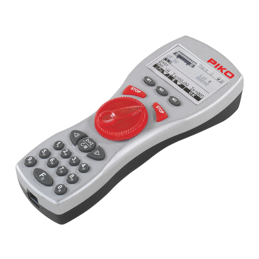
PIKO Navigator 1. Beschreibung Der PIKO Navigator gehört zu den modernsten und komfortabelsten Handreglern für digital gesteuerte Modelleisenbahnanlagen. Seine Funktion beschränkt sich dabei nicht nur auf das reine Steuern von Loks, sondern bietet darüber hinaus auch weitere exklusive Steuermöglich keiten. -
Seite 7: Form & Ergonomie
Batteriekasten ist optimal in die Rückseite des Handreglers integriert. Ein großes Grafikdisplay gibt detaillierte Auskunft über den Zustand der Lok und der Anlage. Der PIKO Navigator bietet die Möglichkeit, zwei Funktionen gleichzeitig auszuführen. Dazu gehören zum Beispiel das Steuern von Loks und das Schalten von Weichen oder Weichenstraßen. -
Seite 8: Eingabe Der Lokadresse Und Erster Fahrbetrieb
Betrieb möglicherweise verbessert werden (siehe Kap. 6.5.1.1) Beim gleichzeitigen Betrieb mehrerer Funk-Navigatoren müssen diese auf verschiedene ID-Nummern programmiert werden. 2.1.4 Betrieb an Fremdzentralen Der PIKO Navigator kann auch mit den MASSOTH Digitalzentralen DiMAX 1200Z, 1210Z, 800Z und MZS III betrieben werden. ®... -
Seite 9: Menü-Übersichtsdiagramm
HAUPTMENÜ Loktraktion Lok fahren Decoder Progr. Lok Adresse Reg Programmieren CV Lesen / Progr. PoM Lokdecoder PoM Schaltdecoder Fahrstraße Automatik Progr. Traktion Navigator Konfig Beleuchtung Loks Sortieren Notausmodus Werkeinstellung Sprache wechseln Spezial Modus ID-Nummer Progr. Sperren Weitere Funksender Konfig Kanalwahl... -
Seite 10: Bedienelemente
PIKO Navigator 2.3 Bedienelemente Der PIKO Navigator verfügt über verschiedene Bedienelemente. Entnehmen Sie dieser graphischen Übersicht die Funktion und Belegung der Tasten des PIKO Navigators. Beschreibung Display Menütasten rechte STOP-Taste linke STOP-Taste Geschwindigkeitsregler Hauptfunktion (nur Loksteuerung) Steuerung der 2. Funktion (Funktion wählbar) -
Seite 11: Das Display
= Internationales Zeichen für Strom I m = I max maximale Strombegrenzung in Ampere (bei PIKO Digitalzentrale 5A) I a = aktuelle Stromaufnahme in Ampere I p = prozentuale Auslastung in % Die Menüzeile zeigt die aktuelle Belegung der 3 Tasten 35017-90-7000_2019_p1-38.indd 9... -
Seite 12: Menü-Tasten
Zeile des Displays mit weißer Schrift auf schwarzen Hintergrund. Hier ein Beispiel: 2.3.3 STOP-Tasten Der PIKO Navigator ist mit einer Hand, sowohl für Rechts,- als auch für Linkshänder gleichermaßen leicht zu bedienen. Deshalb ist der PIKO-Navigator für beste Bedienbarkeit mit 2 Stopp-Tasten ausgestattet, die individuell einstellbar sind. -
Seite 13: Steuerung Der Nebenfunktion
Parallel zur ersten Funktion, kann hier eine zweite Lok, sämtliche Magnet- artikel oder eine Weichenstraße gesteuert und geschaltet werden. 2.3.6 Tastatur Über die Tastatur des PIKO Navigators können bis zu 99 Funktionen verarbeitet werden. Mit der F-Taste kann zwischen den Funktionsebenen gewechselt werden. -
Seite 14: Erste Schritte Zum Fahrbetrieb
PIKO Navigator 3. Erste Schritte zum Fahrbetrieb Die Schritte zum ersten Fahrbetrieb mit dem PIKO Navigator sind sehr einfach und auch ohne Kenntnis schnell durchgeführt. Im Folgenden wird die Einrichtung und Steuerung einer Lok detailliert erklärt. 3.1 Ein- und Ausschalten Bei Kabelanschluss startet der Navigator automatisch. -
Seite 15: Lok Konfiguration
4. Lok Konfiguration 4.1 Zugang zur Lok Konfiguration Legen Sie in der Lok Konfiguration den Funktionsumfang Ihrer Lokomotiven fest. Dazu gehören zum Beispiel Anzahl der Fahrstufen, die Betriebsart, serielle bzw. parallele Datenverarbeitung oder das Lokbild. Durch langes Drücken der Taste gelangen Sie in das Lok Konfigurati onsmenü. -
Seite 16: Konfiguration F-Tasten
PIKO Navigator 4.1.4 Konfiguration F-Tasten Hier haben Sie die Möglichkeit die Tasten 1-8 auf dem Navigator auf Moment- oder Dauer- be trieb zu konfigurieren. Das heißt, sind die Zahlen 1-8 im Display nicht invers abgebildet, so arbeiten die Tasten wie bisher (1 x Drücken entspricht 1 x Anschalten oder Ausschalten). Durch Drücken der entsprechenden Taste wird diese Zahl im Display invers dargestellt (im Bild 2 und 6). -
Seite 17: Konfiguration Speichern
Änderung mit OK bestätigen, wird die Änderung der Lokbezeichnung über nommen und beim nächsten Laden der Konfiguration bzw. des Fahrmodus korrekt als V 51 angezeigt. Der Name wird nur lokal in diesem Navigator gespeichert. So kann auf jedem Navigator für jede Lok ein eigener Wunschname definiert werden. -
Seite 18: Abmelden Einer Lok
Adresse eingegeben oder Lok ausgewählt haben. 4.1.10 Abmelden einer Lok Eine auf dem PIKO Navigator angemeldete Lokomotive ist reserviert und kann durch andere Teilnehmer nicht übernommen werden, wenn diese von Ihnen nicht explizit freigegeben wird. Dies geschieht ganz einfach durch das Öffnen des Lokwahlmenüs (Taste oder ). -
Seite 19: Laden Einer Belegten Lok
Übernahmefunktion (Übernahme belegter Loks) entsprechend zu konfigurieren. 4.1.13 Analoge Lok Natürlich kann auch eine analoge Lok mit dem PIKO Navigator gesteuert werden. Die Adresse einer analogen Lokomotive ist „0“. Die Definition der Lokeigenschaften, wie zum Beispiel Fahrstufen oder Funktionen, ist bei einer analogen Lokomotive nicht möglich. Die Lok Konfiguration kann in diesem Fall nicht ausgeführt werden. -
Seite 20: Funktionen Im Fahrbetrieb
Fahrstraßen schalten oder sogar eine zweite Lok steuern. 5.1 Infomodus Beim Start des PIKO Navigators wird der Infomodus der zweiten Funktion als Standard gela den. Dieser zeigt immer den maximalen Fahrstrom, aktuelle Auslastung in Ampere und Prozent an. Zusätzlich werden Systemmeldungen ausgegeben. -
Seite 21: Schaltbefehle
Durch nochmaliges Drücken von wechseln Sie in den Schaltbefehl-Modus. Geben Sie die Adresse der Weiche über die Tastatur des PIKO Navigators ein und schalten Sie diese mit den Pfeiltasten der 2. Funktion nach links oder rechts. Zusätzlich können Sie mit der runden STOP-Taste die letzten 8 bereits geschalteten Weichen durchblättern. -
Seite 22: Zweite Lok
PIKO Navigator 5.4 Zweite Lok Der PIKO Navigator bietet als Handregler die Möglichkeit, zwei Lokomotiven bzw. Züge gleich zeitig und unabhängig voneinander zu steuern. Um in diesen Modus zu gelangen, drücken Sie so oft bis die Anzeige im Nebenfunktionsfeld Lok : XXX anzeigt. Geben Sie nun die Lokad resse über die Tastatur ein und bestätigen Sie Ihre Wahl anschließend mit der rechten Taste der zweiten Funktion... -
Seite 23: Loktraktion
Das Prinzip der Menüs ist überall gleich. ist Navigieren, ist Bestätigen und Zurückkehren in den Fahrbetrieb. Wechseln Sie also die Auswahl mit bis zum gewünschtem Menüpunkt und bestätigen Sie Ihre Auswahl mit 6.1 Loktraktion Bei einer Loktraktion werden mehrere Loks zu einem Zug zusammengestellt. Das kennt man beispielsweise von langen Güterzügen aus den USA. -
Seite 24: Dekoder Programmierung
Hier wird die Lokadresse der Lok ausgelesen und programmiert. Die Adresse ist wählbar von 1-10239. Der Navigator berechnet automatisch die passenden Programmierwerte für CV 1, 17 und 18 + 29. Zusätzlich können Sie noch angeben ob der Decoder mit 14 oder 28 Fahrstufen betrieben werden soll, die Fahrtrichtung festlegen und den Analogbetrieb sperren. -
Seite 25: Cv Auslesen Und Programmieren
CV programmiert werden, müssen alle Wertigkeiten addiert werden. Eine deaktive Funktion hat immer die Wertigkeit 0, eine aktive Funktion den in der Tabelle angegebenen Wert. Durch Addition der aktiven Funktionen ergibt sich der entsprechene Bit-Wert. Der Navigator zeigt die Bitzustände automatisch in der unteren Zeile zur Kontrolle an. -
Seite 26: Weichen / Schaltdecoder Programmierung (Standard)
Weichendecoder an das Programmiergleis an und schließen Sie die Programmierbrücke oder löschen Sie die Programmiersperre wie in der Weichendecoderanleitung beschrieben. Außerdem muss eine Weiche als Last angeschlossen sein, da sonst die Rückmeldung im Navigator nicht funktioniert. Gehen Sie mit in das Hauptmenü und wählen Sie dort Dekoder Programmierung aus. -
Seite 27: Pom Schaltdecoder
CV und der Wert in Hilfsvariablen gespeichert. Der Dekoder führt anschließend die Programmierung der Daten in der entsprechenden CV selbst durch. Durch den Navigator erfolgt die Eingabe der entsprechenden Werte in Register 6 und Register 5. Die CVs 1 bis 4 werden dabei direkt programmiert, alle höheren CVs per Registerprogrammierung. -
Seite 28: Traktion Programmierung
Lassen Sie die Adresse eines Elements frei und bestätigen dies mit , so wird das als Ende der Fahrstraße erkannt und der Navigator springt wieder in den Fahrbetrieb. Die Fahrstraße ist konfiguriert und kann geschaltet werden. Möchten Sie eine Fahrstraße überarbeiten und beispielsweise das 3. Element löschen, so laden Sie die Konfiguration erneut, bestätigen Sie alle richtigen Elemente mit... -
Seite 29: Beleuchtung
Befehl nicht verstehen. Die Dekoder schalten in diesem Fall nicht ab. 6.4.3 Sprache wechseln Wählen Sie diesen Menüpunkt, wenn Sie den PIKO Navigator auf eine andere Menüsprache umstellen möchten. Die Sprachen sind abhängig von der geladenen Sprachdatei, die Sie via Software-Update (Kap. -
Seite 30: Id-Nummer Einstellen
Ihrer Anlage betreiben. Für jeden weiteren, per Funk betriebenen Navigator müssen Sie dessen Funk-ID manuell einstellen. „ID“ bedeutet Identifikation, beim PIKO Navigator ist es eine Nummer von 1 - 8. Nach dem Einschalten des Navigators wird oben im Display die entsprechende Navigator- ID angezeigt (z.B. „Navi 1“). -
Seite 31: Spezialmodus
, da sonst alle konfigurierten Einträge des Navigators gelöscht werden. Anschließend befindet sich der PIKO Naviga tor wieder im Auslieferungszustand. Es müssen dann alle programmierten Einträge (z.B. Loks, Fahrstraßen, Traktionen, Weichen, ...) neu angelegt werden. Der Navigator wird anschließend neu gestartet. -
Seite 32: Lokdatenbank Sortieren
. Dies kann bis zu 40 Nach Auswahl des Verfahrens mit der Taste startet die Sortierung mit Sekunden dauern. In dieser Zeit darf der Navigator nicht ausgeschaltet werden ! 6.5 Funksender 6.5.1 Funksender Konfi guration Beim PIKO Navigator ist die Funksenderkonfi guration freigeschaltet. -
Seite 33: Akku Ladefunktion
6.5.2 Akku Ladefunktion Aktivieren Sie die Ladefunktion mit . Die Ladefunktion ist abhängig von der Akkuspannung. Im Kabelbetrieb können die Akkus dann aufgeladen werden. Akku laden aus Akku laden ein AUSDRÜCKLICHER HINWEIS: Aktivieren Sie die Ladefunktion des Navigators nur, wenn wiederaufl adbare Akkus (NiMH oder NiCd) eingesetzt sind. Batterien dürfen unter keinen m ständen geladen werden. -
Seite 34: Konfiguration Der Zentrale
PC Modul* mit der neuesten Firmware upgedated werden. * Massoth Zubehör und separates Netzteil erforderlich. 8. Technische Daten Der PIKO Navigator ist ein Steuergerät für digitale Modellbahnanlagen. Beachten Sie für den Betrieb bitte Folgendes: Betrieb per Kabel: Maximaler Spannungsbereich... -
Seite 35: Glossar
9. Glossar • Bit Die kleinste logische Informationseinheit in der digitalen Welt - sie kann entweder 1 (gesetzt) oder 0 (nicht gesetzt) sein. 8 Bit ergeben 1 Byte. • Booster Leistungsverstärker im Digitalsystem, um zusätzlichen Fahrstrom zu erzeugen. • Bus / Bussystem Ein Bussystem stellt eine elektrische Verbindung zwischen einzelnen Steuerkomponenten eines Digitalsystems dar. - Seite 36 PIKO Navigator • Fahrstufen Die maximale Motorkraft wird in Fahrstufen unterteilt. Jede Fahrstufe kann einzeln angesteuert werden. Je mehr Fahrstufen möglich sind desto feiner kann das Fahrzeug gesteuert werden. • Interface Ein Interface stellt generell die Verbindung zwischen dem Digitalsystem und einem Computer her.
-
Seite 37: Warnhinweise
• Der PIKO Navigator kann und darf nur mit den in dieser Anleitung beschriebenen Komponenten betrieben werden. Eine anderweitige Verwendung ist nicht zulässig. • Schließen Sie den PIKO Navigator nur an die in dieser Anleitung beschriebenen Geräte an. Auch wenn andere Geräte die gleichen Steckverbinder verwenden, ist der Betrieb mit diesen Geräten nicht möglich. -
Seite 38: Garantie Und Gewährleistungsanspruch
Bedingungen. Damit haben Sie unabhängig vom Kaufort die Möglichkeit, auch direkt bei PIKO aufgetretene Mängel oder Störungen zu reklamieren. Garantiebedingungen Diese Garantie gilt für PIKO Produkte und Einzelteile, die bei einem PIKO Fachhändler weltweit gekauft wurden. Als Kaufnachweis dient die Kaufquittung. Inhalt der Garantie / Ausschlüsse Die Garantie umfasst nach Wahl von PIKO die kostenlose Beseitigung eventueller Störungen oder... -
Seite 39: Reparatur Und Kundendienst
12. Reparatur und Kundendienst Um Beratung, Hilfestellung oder Servicedienstleistungen in Anspruch zu nehmen, wenden Sie sich bitte an Ihren Fachhändler oder direkt an PIKO. Im Internet finden Sie detaillierte Informationen und Dokumentationen zu diesem Produkt. Dort steht auch eine FAQ-Liste zur Verfügung. - Seite 40 PIKO Navigator 35017-90-7000_2019_p1-38.indd 38 05.06.19 10:03...
- Seite 41 Navigator Op e ration M an u al 06/2019_Software Version 2.01p 35017-90-7000_2019_p40-76.indd 39 05.06.19 10:04...
- Seite 42 Connection ....................43 2.1.1 Switching On and Off .................43 2.1.2 Entering the engine location and first vehicle operation ......44 2.1.2.1 Vehicle operation with the PIKO analog throttle (35002) ......44 2.1.3 Information concerning radio control ............44 2.1.4 Operation with extrinsic command controls ..........44 2.1.5...
- Seite 43 Switch decoder programming ..............62 6.2.7 Register programming / Writing indirectly to CV .........62 Automated programming ................62 6.3.1 Route programming ..................63 6.3.2 Locomotive consist programming ...............63 Navigator configuration ................64 6.4.1 Lighting .......................64 6.4.2 Emergency Stop Mode ................64 6.4.3 Select language ..................65 6.4.4 ID number programming ................65...
-
Seite 44: Description
• Large, back-lit display with easy menu control • Locomotive configuration with alphanumeric names and pictograms • The pictogram library contains the PIKO models and a number of current garden railroad locos • 10,239 available locomotive addresses • 14/28/128 speed steps •... -
Seite 45: Form & Ergonomics
The following explains the setup of the Navigator and the simple control of a locomotive. 2.1 Connection The PIKO Navigator is intended for the direct operation at the PIKO digital central (35010). It can be operated using a cable or radio signals (in connection with the PIKO wireless receiver (35018). After start-up, the PIKO Navigator logs into the command control via the cable or via radio signals. -
Seite 46: Entering The Engine Location And First Vehicle Operation
LOCOMOTIVE CONFIGURATION (point 4 of these instructions). 2.1.2.1 Vehicle operation with the PIKO analog throttle (35002) The Navigator can also be used as a remote control for the PIKO analog throttle (in connection with a PIKO wireless receiver 35018). You can find more specific information regarding connection and the range of functions in the instruction manual for the PIKO controller 35002. -
Seite 47: Menu Overview Diagram
Decoder Progr. Loco Address Reg Programming CV Read / Progr. PoM Loco Addr. PoM Switch Addr. Turnout Route Prg. Automatic Progr. Consist Progr. Navigator Config Backlight Loco sort Factory Settings Emergency Stop Change Language Special Mode ID-Number Progr. Code more... -
Seite 48: Controls
PIKO Navigator 2.3 Controls The PIKO Navigator has a variety of controls available. The function and configuration of the keys on the PIKO Navigator are depicted in this graphic overview. No. Description Display Menu keys Right STOP key Left STOP key... -
Seite 49: The Display
The secondar function field displa s the following information when activated = International symbol for electric current I m = maximum current limit in amperes (for PIKO digital command control 5A) I a = current power consumption in amperes I p = workload in % The menu bar displays the current configuration of the 3 key 35017-90-7000_2019_p40-76.indd 47... -
Seite 50: Menu Keys
EMERGENCY STOP or a simple STOP LOCOMOTIVE. The configuration of the STOP function is performed in the menu of the PIKO Navigator (Chapter 5.4.2). In the factory default settings, the EMERGENCY STOP is initiated using the right STOP key That means that current to the tracks is immediately shut off. -
Seite 51: Control Of Secondary Functions
. Likewise, the keyboard can be switched from the secondary functions to the primary functions. If you are operating the PIKO Navigator in radio operation, it can be switched on and off by pressing the key 2.3.10 Binary State Functions... -
Seite 52: First Steps Towards Vehicle Operation
PIKO Navigator 3. First steps towards vehicle operation. The steps towards initial vehicle operation with the PIKO Navigator are very simple and can be carried out without any specialized knowledge. The set-up and control of a locomotive are explained in detail below. -
Seite 53: Locomotive Configuration
4. Locomotive configuration 4.1 Access to locomotive configuration You determine your locomotive s range of functions during locomotive configuration. This includes, for example, the number of speed steps, the mode of operation, serial or parallel data processing or the locomotive image. Locomotive configuration is accessed b pressing and holding the key. -
Seite 54: F-Key Configuration
PIKO Navigator 4.1.4 F-ke configuration This enables you to configure keys 1-8 on the Navigator for momentary or continuous operation. This means that if numbers 1-8 are not inverted in the display, the keys will continue to function as before (pressing x 1 correlates with switching on or off x 1 x). By pressing the appropriate key, this figure will be displayed as inverted (figures 2 and 6). -
Seite 55: Store Configuration
51 the ne t time the configuration or Driving Mode is loaded. The name is only stored locally in that Navigator. In this way, the personally desired name can be stored for every train on each Navigator. 4.1.7 Store configuration This is where you store the configuration for your locomotive. -
Seite 56: Logging Off Of A Locomotive
PIKO Navigator 4.1.10 Logging off of a locomotive A locomotive that has been logged in on a PIKO Navigator is reserved and cannot be acquired by another participant until that locomotive has been explicitly released. This can be achieved by simply opening the locomotive selection menu (using the key). -
Seite 57: Loading An Engaged Locomotive
4.1.13 Analog locomotive It is of course possible to control an analog locomotive with the PIKO Navigator. The address of an analog locomotive is “0 . It is not possible to define the locomotive characteristics such as speed steps or functions for an analog locomotive. In this instance, locomotive configuration cannot be carried out. -
Seite 58: Vehicle Operation
5.1 Info Mode When the PIKO Navigator is started, the Information Mode for the secondary function is loaded. This always indicates the maximum traction current, the current power usage in amperes and as a percentage. -
Seite 59: Switch Commands
You can change to the Switch Commands Mode by repeatedly pressing the key. Enter the address of the switch via the keypad on the PIKO Navigator and throw it to the left or right using the arrow key on the 2nd function . -
Seite 60: Device Setup
6. Device setup The device setup of the handheld controller as well as various system configurations can be performed in the Navigator’ s menu. Use the key to exit vehicle operation and access the main menu. The principal underlying the menus is universal. -
Seite 61: Decoder Programming
Should this occur, select a different consist using or exit consist mode using The primary function of the Navigator can be toggled between controlling a locomotive or a locomotive consist. The first entry in the menu will no longer be the option locomotive consist, but rather drive locomotive. -
Seite 62: Locomotive Address
The decoder readout is not a programming variant however it is indispensible for monitoring programmed settings. The Navigator supports this readout procedure. In so doing, individual settings can easily be checked. The CV (configuration variable) to be read is entered into the Navigator and can been read out with... -
Seite 63: Writing Bit By Bit To Cv (Informatively)
A disabled function always has a value of 0 and active function will have the value indicated in the table. Add all active values and program the result into the CV. The Navigator automatically shows the bit conditions in the lowest row of the display for control. -
Seite 64: Switch Decoder Programming
The decoder subsequently programs the data into the appropriate CV itself. The appropriate values are entered into register 6 and register 5 using the Navigator. CVs 1 through 4 are thereby programmed directly while all higher CVs are programmed via register programming. -
Seite 65: Route Programming
. Up to 15 elements can be configured into a route. The PIKO Navigator automatically counts the elements in ascending order. Simply enter the address of the first element and define the direction in which the switch is thrown using the arrow key . -
Seite 66: Navigator Configuration
PIKO Navigator 6.4 Navigator configuration In the Navigator configuration menu, you can implement specific settings for the PIKO Navigator. It is here that you switch the lighting on and off, define the Emergency Stop Mode, select the preferred language, manually program the ID number for your Navigator, lock the Navigator against modifications and, in the advanced configuration mode, where you can restore the device s factory settings. -
Seite 67: Select Language
NOTE: If you choose the RIGHT option, for example, you will initiate the EMERGENCY STOP using the right STOP key. If you have initiated an EMERGENCY STOP, both STOP keys on the Navigator will be blinking red. The voltage on the track will be shut off. You can use the left button to cancel the EMERGENCY STOP. -
Seite 68: Locks
NOTE: Should you ever lose your activation code, contact us by Email (hotline@piko. de) with your Navigator’ s serial code. This can be located in two places. When switching on your Navigators, press and hold the F key. The serial number will be visible on the left. -
Seite 69: Special Mode
In order to access this menu, first select more using with nl confirm the restoration of factor settings on the K Navigator if ou are absolutel . If you certain that you want that. Otherwise you can navigate away from this menu using restore factor settings all configured entries in the navigator will be deleted. -
Seite 70: Sort The Loco Database
The shut down time determines the length of time for which the radio connection to the wireless receiver is maintained until the navigator automatically logs of when there has been no input. When shutting down or in the event of a loss of signal, all allocated locomotives are automatically logged off. -
Seite 71: Battery Charge Function
Battery charge off Battery charge on IMPORTANT NOTE: only activate the charge function on the Navigator if rechargeable batteries have been installed. Non-rechargeable batteries may not be recharged under any circumstances. This will destroy the battery. There is a risk of explosion! The battery symbol displays the charge left on a battery. -
Seite 72: Command Control Configuration
This function is reserved for future application. 7. Software update In the future, PIKO will offer updates at irregular time intervals, which we will announce on our homepage www.piko.de . A software update can be done in our factory or by authorized dealers. -
Seite 73: Glossary
9. Glossary • Bit A bit is the smallest unit of information in the digital world. It can be either 1 (set) or 0 (not set). 8 bits comprise a byte. • Booster Power amplifier in a digital system used to generate additional current. •... - Seite 74 PIKO Navigator • Digital address In order to access individual vehicles or components such as switches with a digital system, each of these objects requires a unique, numeric address. Depending upon the digital system, a greater or lesser number of addresses can be invoked.
-
Seite 75: Warnings
This will lead to damage to the PIKO Navigator as well as other components. • Please ensure that the PIKO Navigator is not dropped or allowed to fall. Do not subject it to blows or jostling. This can lead to damage of the equipment. -
Seite 76: Warranty Conditions
PIKO dealer as the contractual selling party. This warranty is given with the following conditions listed below. Regardless of where you purchased the product, you thereby have the possibility of submitting for warranty claim defects or flaws occurring with the product to the firm of PIKO as the manufacturer of the product. - Seite 77 REGULATORY INFORMATION: 1. FCC Information (USA): This device contains FCC ID: WAP4110. The device CYBLE-224110-00 complies with Part 15 of the FCC Rules. The device meets the requirements for the modular transmitter approval as detailed in FCC public Notice DA00-1407. Transmitter Operation is subject to the following two condi- tions: (1) This device may not cause harmful interference, and (2) This device must accept any interference received, including interference that may cause undesired operation.
- Seite 78 PIKO Navigator 35017-90-7000_2019_p40-76.indd 76 05.06.19 10:04...
- Seite 79 35017-90-7000_2019_cover.indd 5 05.06.19 10:07...
- Seite 80 PIKO Spielwaren GmbH Lutherstr. 30 96515 Sonneberg, GERMANY www.piko.de · hotline@piko.de 35017-90-7000_2019_cover.indd 2 05.06.19 10:07...