Inhaltsverzeichnis
Werbung
Verfügbare Sprachen
Verfügbare Sprachen
Quicklinks
Werbung
Kapitel
Inhaltsverzeichnis

Verwandte Anleitungen für MICRO-EPSILON wireSENSOR WDS series


Inhaltszusammenfassung für MICRO-EPSILON wireSENSOR WDS series
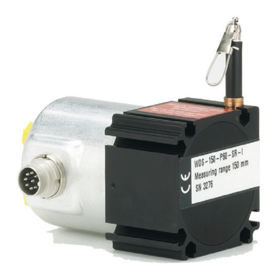
- Seite 1 Betriebsanleitung Operating Instructions wireSENSOR P115...
-
Seite 2: Einbauerklärung
Einbauerklärung Einbauerklärung nach der EG-Maschinenrichtlinie 2006/42/EG, Anhang II B Hersteller und bevollmächtigte Person für die Zusammenstellung der relevanten technischen Unterlagen MICRO-EPSILON MESSTECHNIK GmbH & Co. KG Königbacher Straße 15 94496 Ortenburg / Deutschland erklärt hiermit, dass die nachfolgend bezeichnete Maschine auf Grund ihrer Konzipierung und Bauart sowie in der von ihr in Verkehr gebrachten Ausführung - soweit es vom Lieferumfang möglich ist - den einschlägigen grundlegenden Sicherheits- und Gesundheits-... - Seite 3 Bestimmungen der EG-Maschinenrichtlinie entspricht und für die eine EU-Konformitätserklärung gemäß Anhang II A vorliegt. Ortenburg, 22. Mai 2019 Dr. Thomas Wisspeintner Geschäftsführer Tel. +49 (0) 8542 / 168-0 e-mail info@micro-epsilon.de Fax +49 (0) 8542 / 168-90 www.micro-epsilon.de...
-
Seite 5: Inhaltsverzeichnis
Inhalt Sicherheit ..........................7 Verwendete Zeichen ............................7 Warnhinweise ..............................7 Hinweise zur CE-Kennzeichnung ........................9 Bestimmungsgemäße Verwendung ......................10 Bestimmungsgemäßes Umfeld ........................10 Vorhersehbare Fehlanwendung ........................10 Funktionsprinzip, Technische Daten ..................11 Messprinzip ..............................11 Aufbau, elektrischer Anschluss ........................11 Technische Daten Modell P60 Analog...................... - Seite 6 Bedienung..........................42 Betrieb und Wartung ......................42 Haftung für Sachmängel ......................43 Service, Reparatur ........................43 Außerbetriebnahme, Entsorgung ..................44 Anhang Zubehör und Ersatzteilliste ....................45 Anschlussbelegung und Farbcode Anschlusskabel PC3/8 ..........46 Maßzeichnungen und Hinweise für Zubehör ................ 47 wireSENSOR, WDS P60/P96/P115...
-
Seite 7: Sicherheit
Sicherheit Sicherheit Die Sensorhandhabung setzt die Kenntnis der Betriebsanleitung voraus. Verwendete Zeichen In dieser Betriebsanleitung werden folgende Bezeichnungen verwendet. Zeigt eine gefährliche Situation an, die zu geringfügigen oder mittelschweren Verletzungen führt, falls diese nicht vermieden wird. Zeigt eine Situation an, die zu Sachschäden führen kann, falls diese nicht vermieden wird. - Seite 8 Sicherheit Ziehen Sie das Messseil nicht über den angegebenen Messbereich heraus. > Verletzungsgefahr > Zerstörung des Messseils > Zerstörung des Sensors Schließen Sie die Spannungsversorgung und das Anzeige-/Ausgabegerät nach den Sicherheitsvorschriften für elektrische Betriebsmittel an. > Beschädigung oder Zerstörung des Sensors Vermeiden Sie Stöße und Schläge auf den Sensor.
-
Seite 9: Hinweise Zur Ce-Kennzeichnung
Diese Sensoren tragen das CE-Kennzeichen und erfüllen die Anforderungen der zitierten EU-Richtlinien und der dort aufgeführten europäischen harmonisierten Normen (EN). Die EU-Konformitätserklärung wird für die zuständige Behörde zur Verfügung gehalten bei MICRO-EPSILON MESSTECHNIK GmbH & Co. KG Königbacher Straße 15 94496 Ortenburg / Deutschland Seilzug-Wegsensoren mit Potentiometerausgang sind nicht selbstständig betreibbare Geräte (Komponenten) -
Seite 10: Bestimmungsgemäße Verwendung
Sicherheit Bestimmungsgemäße Verwendung Seilzug-Wegsensoren werden eingesetzt zur - Weg- oder Abstandsmessung - Positionserfassung von Bauteilen oder beweglichen Maschinenkomponenten. - Die Sensoren dürfen nur innerhalb der in den technischen Daten angegebenen Grenzen betrieben wer- den, siehe Kap. - Seilzug-Wegsensoren sind so einzusetzen, dass bei Fehlfunktionen oder Totalausfall des Sensors keine Personen gefährdet oder Maschinen und andere materielle Güter beschädigt werden. -
Seite 11: Funktionsprinzip, Technische Daten
Funktionsprinzip, Technische Daten Funktionsprinzip, Technische Daten Messprinzip Mit dem Seilzugprinzip wird eine Linearbewegung in eine Widerstandsänderung transformiert. Ein Messseil aus hochflexiblen rostfreien Stahladern wird auf eine Trommel mit Hilfe eines langlebigen Federmotors aufgewickelt. Die Wickeltrommel ist axial mit einem - Mehrgang-Potentiometer (Typ WDS - ... - Pxx - ... - P/U/I) beziehungsweise mit einem - Encoder (Typ WDS - ... -
Seite 12: Technische Daten Modell P60 Analog
Funktionsprinzip, Technische Daten Technische Daten Modell P60 Analog Modell WDS- 100-P60 150-P60 300-P60 500-P60 750-P60 1000-P60 1500-P60 Verfügbare Ausgangsarten P/U/I P/U/I P/U/I P/U/I P/U/I P/U/I P/U/I Messbereich 1000 1500 0,75 ±0,1 % d.M ± Linearität 0,75 ±0,25 % d.M ± 0,75 ±0,5 % d.M ±... -
Seite 13: Technische Daten Modell P96 Und P115 Analog
Funktionsprinzip, Technische Daten Technische Daten Modell P96 und P115 Analog 2000- 2500- 3000- 4000- 5000- 7500- 10000- 15000- Modell WDS- P115 P115 P115 P115 P115 P115 Verfügbare Ausgangsarten P/U/I Messbereich 2000 2500 3000 4000 5000 7500 10000 15000 ±0,1 % d.M ±... - Seite 14 Funktionsprinzip, Technische Daten Ausführung mit Potentiometerausgang WDS - ..- Pxx - P Elektrische Daten Eingangsspannung: Max. 32 VDC bei 1 kOhm / max. 1 W Widerstand: 1 kOhm ±10 % (Widerstandsteiler) £ 3 mA Schleiferstrom: Temperaturkoeffizient: ±0,0025 % des Messbereichs/K Empfindlichkeit: messbereichsabhängig, individuelle Angabe auf Typenschild Elektrischer Anschluss:...
- Seite 15 Funktionsprinzip, Technische Daten Ausführung mit Stromausgang (2-Draht), WDS - ..- Pxx - SR - I Elektrische Daten Betriebsspannung: 14 bis 27 VDC unstabilisiert, gemessen an den Eingangsklemmen am Sensor Stromaufnahme: 35 mA max. Ausgangsstrom: 4 bis 20 mA Bürde: <...
-
Seite 16: Technische Daten Modell P60 Digital
Funktionsprinzip, Technische Daten Technische Daten Modell P60 Digital Modell WDS-1000-P60 WDS-1500-P60 Ausgangsart HTL, TTL, PB, CO, SSI Messbereich 1000 mm 1500 mm Linearität ±0,02 % d.M. ±0,2 mm ±0,3 mm Auflösung HTL, TTL 0,067 mm (15 Pulse/mm) 0,1 mm (10 Pulse/mm) Auflösung SSI, PB, CO 0,012 mm 0,018 mm... -
Seite 17: Technische Daten Modell P96 Digital
Funktionsprinzip, Technische Daten Technische Daten Modell P96 Digital Modell WDS-3000-P96 Ausgangsart HTL, TTL, SSI, PB, CO Messbereich 3000 mm Linearität ±0,02 % d.M. ±0,6 mm Auflösung HTL, TTL 0,087 mm (11,53 Pulse/mm) Auflösung SSI, PB, CO 0,032 mm Sensorelement Inkremental-/Absolutencoder Temperaturbereich -20 ... -
Seite 18: Technische Daten Modell P115 Digital
Funktionsprinzip, Technische Daten Technische Daten Modell P115 Digital WDS-5000- WDS-7500- WDS-10000- WDS-15000- Modell P115 P115 P115 P115 Messbereich 5000 mm 7500 mm 10000 mm 15000 mm Ausgangsart HTL, TTL, SSI, PB, CO ±0,01 % d.M. ±1 mm ±1,5 mm Linearität ±0,02 % d.M. -
Seite 19: Lieferung
Lieferung Lieferung Lieferumfang Nehmen Sie die Seilzug-Wegsensoren nicht am Seil, Seil-Gewindebolzen oder Seilhaken aus der Verpackung. Transportieren Sie die Sensoren so, dass keine Beschädigung auftreten kann. Prüfen Sie die Lieferung nach dem Auspacken sofort auf Vollständigkeit und Transportschäden. Wenden Sie sich bitte bei Schäden oder Unvollständigkeit sofort an den Hersteller oder Lieferanten. Die Transportsicherung für das Messseil darf erst unmittelbar vor der Montage und nur durch Fachper- sonal entfernt werden. -
Seite 20: Installation Und Montage
Installation und Montage Installation und Montage Vorsichtsmaßnahmen Freier Rücklauf des Messseils nicht zuläs- Ziehen Sie das Messseil nicht über den Messbereich heraus. sig! > Beschädigung oder Zerstörung des Sensors möglich > Verletzungsgefahr durch Peitschenwir- Beschädigen Sie nicht das Messseil. kung des Seils mit Montagebolzen/- Ölen oder fetten Sie nicht das Messseil. - Seite 21 Installation und Montage MB (mm) A (mm) 100/300/500/1000 16,15 150/750/1500 24,2 Montagenuten für Mutter M4 DIN 934 oder Schraube M4 DIN 931 Kabelbiegung: R > 15, einmalig R > 50, mehrmalig Ein gespanntes Messseil kann im 38,6 1) max. Einschraub- Aufenthaltsbereich von tiefe 76,5...
- Seite 22 Installation und Montage MB (mm) A (mm) 1000 16,15 1500 24,2 Ein gespanntes Messseil kann im Aufenthaltsbereich von 38,6 10,7 Bedienungspersonal zu Verletzungen führen. > Beschädigungs- Abb. 4 Maßzeichnung WDS- ... - P60 - CR - HTL/TTL, Maße in mm, nicht maßstabsgetreu gefahr für Seil und Sensor MB (mm) A (mm)
- Seite 23 Installation und Montage Ein gespanntes Messseil kann im MB (mm) A (mm) 1000 16,15 Aufenthaltsbereich von 1500 24,2 Bedienungspersonal zu Verletzungen führen. > Beschädigungs- gefahr für Seil und Sensor 38,6 10,7 21,3 Verdrillen Sie nicht das Messseil! Abb. 6 Maßzeichnung WDS- ... - P60 - CAN/PB, Maße in mm, nicht maßstabsgetreu wireSENSOR, WDS P60/P96/P115 Seite 23...
-
Seite 24: Installation Und Montage
Installation und Montage Kabelbiegung WDS - P96: R > 20 einmalig R > 75 wechselnd 40 bzw. 100 für CAN-Bus Ein gespanntes 4x M6 Messseil kann im 2x Nutenstein Aufenthaltsbereich von 2x Befestigungsschraube M4 Bedienungspersonal zu Verletzungen führen. Abb. 7 Maßzeichnung WDS- ... - P96 - CA - P , Maße in mm, nicht maßstabsgetreu >... - Seite 25 Installation und Montage ø30 ø20,2 Ein gespanntes 4x M6 Messseil kann im 2x Nutenstein Aufenthaltsbereich von 2x Befestigungsschraube M4 Bedienungspersonal zu Verletzungen führen. Abb. 9 Maßzeichnung WDS- ... - P96 - HTL/TTL, Maße in mm, nicht maßstabsgetreu > Beschädigungs- gefahr für Seil und Sensor ø13 Verdrillen Sie nicht das...
- Seite 26 Installation und Montage Ein gespanntes Messseil kann im ø13 Aufenthaltsbereich von Bedienungspersonal zu Verletzungen führen. > Beschädigungs- gefahr für Seil und Sensor 4x M6 2x Nutenstein Verdrillen Sie nicht das 2x Befestigungsschraube M4 Messseil! Abb. 11 Maßzeichnung WDS- ... - P96 - CO/PB, Maße in mm, nicht maßstabsgetreu Modell WDS-2000-P96 WDS - P96 - CA - P...
- Seite 27 Installation und Montage Kabelbiegung 17,6 WDS - P115: R > 20 einmalig R > 75 wechselnd 40 bzw. 100 für CAN-Bus Ein gespanntes Messseil kann im 4x M6 Aufenthaltsbereich von 2x Nutenstein P115-SR-U/I 2x Befestigungsschraube M4 Bedienungspersonal zu P115-CA-P Abdeckschraube für Gain u. ZERO-Poti Verletzungen führen.
- Seite 28 Installation und Montage ø30 ø20,2 Ein gespanntes 4x M6 Messseil kann im 2x Nutenstein Aufenthaltsbereich von 2x Befestigungsschraube M4 Bedienungspersonal zu Verletzungen führen. Abb. 14 Maßzeichnung WDS- ... - P115 - HTL/TTL, Maße in mm, nicht maßstabsgetreu > Beschädigungs- gefahr für Seil und ø30 Sensor ø20,2...
- Seite 29 Installation und Montage ø30 ø20,2 Ein gespanntes Messseil kann im Aufenthaltsbereich von Bedienungspersonal zu Verletzungen führen. > Beschädigungs- gefahr für Seil und Sensor 4x M6 2x Nutenstein 2x Befestigungsschraube M4 Verdrillen Sie nicht das Messseil! Abb. 16 Maßzeichnung WDS- ... - P115 - CO/PB, Maße in mm, nicht maßstabsgetreu Modell WDS - P115 - U/I/P WDS-3000-P115...
-
Seite 30: Seilführung Und -Befestigung
Installation und Montage Seilführung und -befestigung Muss für die Seilführung bzw. das Befestigen am Messobjekt Ein gespanntes das Messseil aus dem Sensor herausgezogen werden, Messseil kann im Aufenthaltsbereich von - darf dabei der Sensor nicht durch eine zweite Person gehal- Falsch Bedienungspersonal zu ten werden... -
Seite 31: Anschlussbelegung
Installation und Montage Anschlussbelegung 4.4.1 Potentiometer, Strom- und Spannungsausgang Elektrischer Anschluss Ausgang Seilzug Wegsensoren mit Potentiometerausgang wer- - CR - integriertes Kabel - SR - Stecker radial - P - Potentiometer den gemäß Farb-Belegung, Farbe DIN 47 100 siehe Abb. 18, siehe Abb. - Seite 32 Installation und Montage Eingang + Masse 100 % Signal Abb. 20 Ausführung mit Potentiometerausgang Verwenden Sie das Potentiometer nur als Spannungsteiler, nicht als variablen Vorwiderstand! Die Verwendung als variabler Widerstand zerstört das Element. Beachten Sie die maximalen Schleiferströme. Seilzug-Wegsensoren mit Spannungs- oder Stromausgang werden über den 8-poligen Einbaustecker ge- mäß, siehe Abb.
- Seite 33 Installation und Montage Abb. 21 Ausführung mit Spannungs- Versorgung ausgang Masse zero gain Signal Masse 0 - 10 V Ansicht Lötstift- seite 8-polige An- schlussbuchse Versorgung Masse zero gain 4 - 20 mA Abb. 22 Ausführung mit Stromausgang wireSENSOR, WDS P60/P96/P115 Seite 33...
-
Seite 34: Ttl, Htl
Installation und Montage 4.4.2 TTL, HTL Beachten Sie bei Seilzug-Wegsensoren mit Encoder-Ausgang bitte die entsprechende Anschlussbele- gung und weitere Bedienhinweise, die zusammen mit dem Sensor mitgeliefert werden. Ausgangssignale Ausgang TTL Linedriver (5 VDC) Pegel High ≥ 2,5 V (bei I = -20 mA) Spur A Pegel Low ≤... - Seite 35 Installation und Montage Anschlussbelegung TTL, HTL Stecker Kabelfarbe Belegung Pin 1 rosa Spur B inv. Pin 2 blau UB Sense Pin 3 Spur N (Nullimpulse) Pin 4 schwarz Spur N inv. (Nullimpulse inv.) Pin 5 braun Spur A Pin-Seite Sensorstecker Pin 6 grün Spur A inv.
-
Seite 36: Ssi
Installation und Montage 4.4.3 Beschreibung der Anschlüsse 1 UB Versorgungsanschluss des Drehgebers. 2 GND Masseanschluss des Drehgebers. Die zu GND bezogene Spannung ist UB. 3 Takt + Positiver SSI Takteingang. Takt + bildet mit Takt - eine Stromschleife. Ein Strom von ca. 7 mA in Richtung Takt+ Eingang bewirkt eine logische 1 in positiver Logik. - Seite 37 Installation und Montage Anschlussbelegung SSI Stecker Kabelfarbe Belegung Pin 1 braun Pin 2 schwarz Pin 3 blau Takt + Pin 4 beige Daten + Pin 5 grün NULL Pin 6 gelb Daten - Pin 7 violett Takt - Pin-Seite Sensorstecker DATAVALID Pin 8 braungelb...
-
Seite 38: Canopen
Installation und Montage 4.4.4 CANopen CANopen Merkmale Bus-Protokoll CANopen Device-Profil CANopen - CiA DSP 406, V 3.0 CANopen Features Device Class 2, CAN 2.0B Betriebsarten Polling Mode (asynch, über SDO) (mit SDO progr.) Cyclic Mode (asynch-cyclic): Der Geber sendet zyklisch – ohne Aufforderung durch einen Master –... - Seite 39 Installation und Montage Einstellung der Baudrate CANopen Baudrate Einstellung Dip-Schalter 10 kBit/s 20 kBit/s 50 kBit/s 12 kBit/s Einstellung des Abschlusswiderstandes 250 kBit/s CANopen 500 kBit/s 800 kBit/s 1 MBit/s ON = Letzter Teilnehmer OFF = Teilnehmer X Beschreibung der Anschlüsse CANopen CAN_L CAN Bus Signal (dominant Low) Einstellungen der...
-
Seite 40: Profibus
Installation und Montage 4.4.5 Profibus Profibus-DP Merkmale Bus-Protokoll Profibus-DP Profibus Features Device Class 1 und 2 Data Exchange Funktionen Input: Positionswert Zusätzlich parametrierbares Geschwindigkeitssignal (Ausgabe der aktuellen Drehgeschwindigkeit) Output: Preset-Wert Preset-Wert Mit dem Parameter „Preset“ kann der Geber auf einen gewünschten Istwert gesetzt werden, der einer definierten Achsposition des Systems entspricht. - Seite 41 Installation und Montage Beschreibung der Anschlüsse Profibus-DP Negative serielle Datenleitung Positive serielle Datenleitung Versorgungsspannung 10 ... 30 VDC Masseanschluss für UB (Klemmen mit gleicher Bezeich- nung sind intern miteinander Einstellung des verbunden) Abschlusswiderstandes Profibus-DP ON = Letzter Teilnehmer OFF = Teilnehmer X Einstellungen der Teilnehmeradresse Profibus Adresse über Drehschalter erreichbar.
-
Seite 42: Bedienung
Beachten Sie die Hinweise zur Seilführung, siehe Kap. 4.3, während des Betriebs. Nicht einwandfreie Seilführung kann zu erhöhtem Verschleiß und frühzeitigem Defekt führen. Bei Eingriff durch Dritte erlöschen die Haftung für Sachmängel und jeglicher Haftungsanspruch. Reparaturen werden ausschließlich von MICRO-EPSILON durchgeführt, siehe Kap. wireSENSOR, WDS P60/P96/P115 Seite 42... -
Seite 43: Haftung Für Sachmängel
Die Haftung für Sachmängel beträgt 12 Monate ab Lieferung. Innerhalb dieser Zeit werden fehlerhafte Teile, ausgenommen Verschleißteile, kostenlos instandgesetzt oder ausgetauscht, wenn das Gerät kostenfrei an MICRO-EPSILON eingeschickt wird. Nicht unter die Haftung für Sachmängel fallen solche Schäden, die durch unsachgemäße Behandlung oder Gewalteinwirkung entstanden oder auf Reparaturen oder Verände- rungen durch Dritte zurückzuführen sind. -
Seite 44: Außerbetriebnahme, Entsorgung
Außerbetriebnahme, Entsorgung Außerbetriebnahme, Entsorgung Entfernen Sie das Versorgungs- und Ausgangskabel am Sensor. Durch falsche Entsorgung können Gefahren für die Umwelt entstehen. Entsorgen Sie das Gerät, dessen Komponenten und das Zubehör sowie die Verpackungsmaterialien entsprechend den einschlägigen landesspezifischen Abfallbehandlungs- und Entsorgungsvorschriften des Verwendungsgebietes. -
Seite 45: Anhang
Anhang | Zubehör und Ersatzteilliste Anhang Zubehör und Ersatzteilliste PC3/8 Anschlusskabel, 3 m lang mit Kabelbuchse/Litzen, IP 40 Kabelbuchse für Standardmodelle, 8-polig DIN 45 326, IP 40, inclusive Schraubendreher FC8/90 Kabelbuchse 90 ° gewinkelt für Standardmodelle, 8-polig DIN 45 326, IP 65 MH1-WDS Magnethalter mit Bohrung für M4-Seilanschluss Seilhaken oder Gabelkopf, siehe... -
Seite 46: A 2 Anschlussbelegung Und Farbcode Anschlusskabel Pc3/8
Anhang | Anschlussbelegung und Farbcode Anschlusskabel PC3/8 Anschlussbelegung und Farbcode Anschlusskabel PC3/8 Adernfarbe Belegung weiß Eingang + Versorgung + Versorgung + grün n.c. n.c. n.c. Äußerer Kabelbereich braun Masse Masse Masse mit Gesamtschirm gelb n.c. Masse n.c. grau n.c. n.c. n.c. -
Seite 47: A 3 Maßzeichnungen Und Hinweise Für Zubehör
Anhang | Maßzeichnungen und Hinweise für Zubehör Maßzeichnungen und Hinweise für Zubehör Montagehinweise für Magnethalter MH1 - WDS Senkrechte Abzugskraft auf planer St 37-Platte ca. 18 kg bei 20 °C. Die Verschiebekraft beträgt je nach Beschaffenheit der Oberfläche etwa 20 - 35 % der Haltekraft. Gebrauchstemperatur: -40 bis +120 °C Temp.- Koeffizient der Haltekraft (reversibel): -4 % pro 10 °C bei 20 °C Starke Vibrationen können ein „Wandern“... - Seite 48 Anhang | Maßzeichnungen und Hinweise für Zubehör Montagehinweise für Magnethalter MH2 - WDS Senkrechte Abzugskraft auf planer St 37-Platte ca. 13 kg bei 20 °C. Die Verschiebekraft beträgt je nach Beschaffenheit der Oberfläche etwa 20 - 35 % der Haltekraft. Gebrauchstemperatur: -40 bis +120 °C Temp.- Koeffizient der Haltekraft (reversibel): -4 % pro 10 °C bei 20 °C Starke Vibrationen können ein „Wandern“...
- Seite 49 Anhang | Maßzeichnungen und Hinweise für Zubehör Abstand so klein einstellen, dass das Seil nicht abspringen kann! SW3 DIN911 2xM4 DIN84/912 SW3 DIN911 Abb. 25 Umlenkrolle TR1-WDS mit Montagefuß, (Abmessungen in mm, nicht maßstabsgetreu) wireSENSOR, WDS P60/P96/P115 Seite 49...
- Seite 50 Anhang | Maßzeichnungen und Hinweise für Zubehör ø21 ø4,3 Abb. 26 Umlenkrolle TR3-WDS, fest, mit Montagefuß, (Abmessungen in mm, nicht maßstabsgetreu) wireSENSOR, WDS P60/P96/P115 Seite 50...
- Seite 51 Anhang | Maßzeichnungen und Hinweise für Zubehör Abb. 27 Gabelkopf mit Federklappbolzen GK1-WDS, (Abmessungen in mm, nicht maßstabsgetreu) 1 Satz besteht aus: 2 Stück Montageflansch, Alu eloxiert 2 Stück Schraube M4x20 DIN 933-A2 2 Stück Zahnscheibe J4.3 DIN 6797 2 Stück Mutter M4 DIN 934-A2 Abb.
- Seite 52 Anhang | Maßzeichnungen und Hinweise für Zubehör Lieferumfang: 1 Stück Verlängerungsseil 2 Stück Mutter M4 DIN 934-A2 2 Stück Zahnscheibe J4.3 DIN 6797 1 Stück Abstandsbolzen M4 15lg. ø7,5 ø7,5 ø0,54 ø0,45 ø3 Ringöse 2 mm dick Abb. 30 Abb. 29 Seilverlängerung WE-xxxx-M4 Seilverlängerung WE-xxxx-CLIP wireSENSOR, WDS P60/P96/P115 Seite 52...
- Seite 54 Contents Safety ............................57 Symbols Used ............................... 57 Warnings ................................ 57 Notes on CE Marking ............................ 59 Intended Use ..............................60 Proper Environment ............................60 Foreseeable Misuse ............................60 Functional Principle, Technical Data ..................61 Functional Principle ............................61 Structure, Electrical Connection ........................61 Technical Data Model P60 Analog.........................
- Seite 55 Operation ..........................92 Operation and Maintenance ....................92 Liability for Material Defects ....................93 Service, Repair ........................93 Decommissioning, Disposal ....................94 Appendix Accessories and Spare Parts ....................95 Cable Connection and Color Code Connection cable PC3/8 ..........96 Drawings and References for Attachment ................97 wireSENSOR, WDS P60/P96/P115...
- Seite 56 wireSENSOR, WDS P60/P96/P115...
-
Seite 57: Safety
Safety Safety System operation assumes knowledge of the operating instructions. Symbols Used The following symbols are used in these operating instructions: Indicates a hazardous situation which, if not avoided, may result in minor or mode- rate injury. Indicates a situation that may result in property damage if not avoided. Indicates a user action. - Seite 58 Safety Do not pull the measuring wire over measuring range. > Destruction of the measuring wire > Destruction of the sensor > Danger of injury Connect the power supply and the display/output device according to the safety regulations for electrical equipment.
-
Seite 59: Notes On Ce Marking
These sensors carry the CE mark and satisfy the requirements of the EU Directives cited and the European harmonized standards (EN) listed therein. The EU Declaration of Conformity is available to the responsible authorities at: MICRO-EPSILON MESSTECHNIK GmbH & Co. KG Königbacher Straße 15... -
Seite 60: Intended Use
Safety Intended Use Draw wire sensors are used for - distance or displacement measuring - position determination of components or moving machine parts. - The sensors must only be operated within the limits specified in the technical data, see Chap. - Draw wire sensors must be used in such a way that no persons are endangered or machines and other material goods are damaged in the event of malfunction or total failure of the sensor. -
Seite 61: Functional Principle, Technical Data
Functional Principle, Technical Data Functional Principle, Technical Data Functional Principle With the wire principle, a linear motion is transformed into a change in resistance by a rotation. A measuring wire made of highly flexible stainless steel wires is wound onto a drum with the aid of a long life spring motor. -
Seite 62: Technical Data Model P60 Analog
Functional Principle, Technical Data Technical Data Model P60 Analog Model WDS- 100-P60 150-P60 300-P60 500-P60 750-P60 1000-P60 1500-P60 Output type P/U/I P/U/I P/U/I P/U/I P/U/I P/U/I P/U/I Measuring range mm (inch) 100 (3.94) 150 (5.91) 300 (11.8) 500 (19.7) 750 (29.5) 1000 (39.4) 1500 (59.1) mm (inch) 0.5 (0.02) 0.75 (0.03) 1 (0.04) -
Seite 63: Technical Data Model P96 And P115 Analog
Functional Principle, Technical Data Technical Data Model P96 and P115 Analog 2000- 2500- 3000- 4000- 5000- 7500- 10000- 15000- Model WDS- P115 P115 P115 P115 P115 P115 Output type P/U/I 2000 2500 3000 4000 5000 7500 10000 15000 Measuring range (inch) (78.7) (98.4) - Seite 64 Functional Principle, Technical Data Models with potentiometric output WDS - ..- Pxx - CR - P Electrical data Supply voltage: max. 32 VDC at 1 kOhm / max. 1 W Resistance: 1 kOhm ±10 % (potentiometer) £ 3 mA Viper current: Temperature coefficient: ±0.0025 % FSO/K (±0.0014 % FSO/°F) Sensitivity:...
- Seite 65 Functional Principle, Technical Data Models with current output (2-wire) WDS - ..- Pxx - SR - I Electrical data Supply voltage: 14 to 27 VDC non stabilized (measured on the input terminal of the sensor) Current consumption: 35 mA max. Output current: 4 to 20 mA Load:...
-
Seite 66: Technical Data Model P60 Digital
Functional Principle, Technical Data Technical Data Model P60 Digital Model WDS-1000-P60 WDS-1500-P60 Output HTL, TTL, PB, CO, SSI Measuring range 1000 mm 1500 mm Linearity ±0.02 % FSO ±0.2 mm ±0.3 mm Resolution HTL, TTL 0.067 mm (15 pulses/mm) 0.1 mm (10 pulses/mm) Resolution SSI, PB, CO 0.012 mm 0.018 mm... -
Seite 67: Technical Data Model P96 Digital
Functional Principle, Technical Data Technical Data Model P96 Digital Model WDS-3000-P96 Output HTL, TTL, SSI, PB, CO Measuring range 3000 mm Linearity ±0.02 % FSO ±0.6 mm Resolution HTL, TTL 0.087 mm (11.53 pulses/mm) Resolution SSI, PB, CO 0.032 mm Sensor element Incremental-/absolute-encoder Temperature range... -
Seite 68: Technical Data Model P115 Digital
Functional Principle, Technical Data Technical Data Model P115 Digital WDS-5000- WDS-7500- WDS-10000- WDS-15000- Model P115 P115 P115 P115 Measuring range 5000 mm 7500 mm 10000 mm 15000 mm Output HTL, TTL, SSI, PB, CO ±0.01 % FSO ±1 mm ±1.5 mm Linearity ±0.02 % FSO ±1 mm... -
Seite 69: Delivery
Delivery Delivery Unpacking, Included in Delivery Do not unpack the sensor by pulling the wire or wire bolt / clip. Ensure that the goods are forwarded in such a way that no damage can occur. Check the delivery for completeness and shipping damage immediately after unpacking. If there is damage or parts are missing, immediately contact the manufacturer or supplier. -
Seite 70: Installation And Mounting
Installation and Mounting Installation and Mounting Precautionary Measures Uncontrolled retrac- Do not pull the measuring wire over range tion of the measuring > Damage to or destruction of the sensor is possible wire is incorrect! > Danger of injury Do not damage the measuring wire. from whiplash ef- Do not oil or grease the measuring wire. - Seite 71 Installation and Mounting MR (mm) A (mm) 100/300/500/1000 16.15 (.64) 150/750/1500 24.2 (.95) Mounting grooves for nut M4 DIN 934 or bolt M4 DIN 931 Cable bending: (.39) R > 15 (.59), one time R > 50 (1.97), alternating A measuring wire (.28) under tension where operators are...
- Seite 72 Installation and Mounting MR (mm) A (mm) 1000 16.15 (39.97) (.63) 1500 24.2 (59.05) (.95) (.39) A measuring wire under tension where operators are 38.6 10.7 (1.52) (1.57) standing can lead to (.42) (2.36) (2.95) injuries. > Danger of dam- Fig.
- Seite 73 Installation and Mounting A measuring wire MR (mm) A (mm) under tension 1000 16.15 (39.97) (.63) where operators are 1500 24.2 (59.05) (.95) standing can lead to injuries. (.39) > Danger of dam- age to wire and sensor. Do not twist the 38.6 10.7 21.3...
- Seite 74 Installation and Mounting Cable bending WDS - P96: R > 20 one time R > 75 alternating (.37) bzw. 100 (1.57) (3.94) for CAN-bus (1.42) A measuring wire under tension 4x M6 (2.75) (1.97) where operators are 2x Slot nut (3.78) (4.65) 2x Fixation screw M4...
- Seite 75 Installation and Mounting (.39) ø13 (.51 dia.) (.51) (1.42) A measuring wire 4x M6 under tension (2.75) (2.20) (.51) 2x Slot nut (3.78) (4.48) where operators are 2x Fixation screw M4 standing can lead to injuries. Fig. 9 Dimensional drawing WDS- ... - P96 - HTL/TTL, dimensions in mm (inches), not to scale >...
- Seite 76 Installation and Mounting A measuring wire (.39) under tension ø13 where operators are (.51 dia) standing can lead to injuries. (.51) > Danger of dam- (1.42) age to wire and sensor. 4x M6 (2.75) (2.20) (.51) 2x Slot nut (3.78) (6.73) 2x Fixation screw M4 Do not twist the...
- Seite 77 Installation and Mounting Cable bending (3.15) WDS - P115: 17.6 (1.97) (.69) R > 20 one time (.79) R > 75 alternating (2.95) respectively (1.57) for CAN-bus (3.94) (.20) (1.42) (2.36) (1.97) A measuring wire 4x M6 (4.53) (4.84) under tension 2x Slot nut (4.65) P115-SR-U/I...
- Seite 78 Installation and Mounting ø30 (3.15) (1.18 dia.) ø20.2 (.79 dia.) (1.97) (1.42) A measuring wire under tension 4x M6 (2.36) (2.08) where operators are 2x Slot nut (4.53) 2x Fixation screw M4 standing can lead to injuries. Fig. 14 Dimensional drawing WDS- ... - P115 - HTL/TTL, dimensions in mm (inches), not to scale >...
- Seite 79 Installation and Mounting ø30 (3.15) (1.18 dia.) ø20.2 (.79 dia.) A measuring wire (1.97) under tension where operators are standing can lead to injuries. > Danger of dam- (1.42) age to wire and sensor. 4x M6 (2.36) (3.97) 2x Slot nut (4.53) 2x Fixation screw M4 Do not twist the...
-
Seite 80: Wire Guide And Fastening
Installation and Mounting Wire Guide and Fastening If the measuring wire has to be extracted from the sensor to A measuring wire guide the wire respectively to fix it to the target, under tension - the sensor may not be held by another person where operators are Wrong - the measuring wire may not be further extracted but only... -
Seite 81: Pin Assignment
Installation and Mounting Pin Assignment 4.4.1 Potentiometer, Current- and Voltage Output Electrical connection Output Draw wire sensors with poten- tiometer output are connected - CR - - SR - - P - according to the pin assign- Integr. cable Connector Potentiometer ment, see Fig. - Seite 82 Installation and Mounting Input + 100 % Ground Signal Fig. 20 Model with potentiometer output Use the potentiometer only as a voltage divider, not as variable series resistor! Using them as a variable resistor, destroys the element. Ensure that the maximum current through the viper is limited. Draw wire sensors with voltage or current output are connected by the 8-pin built-in plug according to the pin assignment, see Fig.
- Seite 83 Installation and Mounting Fig. 21 Model with voltage Supply output Ground zero gain Signal Ground 0 - 10 V View of solder pin side 8-pole socket Supply Ground zero gain 4 - 20 mA Fig. 22 Model with current output wireSENSOR, WDS P60/P96/P115 Page 83...
-
Seite 84: Ttl, Htl
Installation and Mounting 4.4.2 TTL, HTL Note the pin assignment for draw-wire displacement sensors with encoder output. The sensor contains an additional supplement for detailed information. Output TTL Linedriver (5 VDC) Output signals Level High ≥ 2.5 V (with I = -20 mA) Level Low ≤... - Seite 85 Installation and Mounting Pin assignment TTL, HTL Cable color Assignment pink B inv. blue UB Sense N (reference pulse) black N inv. (reference pulse inv.) brown Pin-side sensor male connector green A inv. Pin 2 and Pin 12 are internally connected grey as well as Pin 11 and 10.
-
Seite 86: Ssi
Installation and Mounting 4.4.3 Contact description 1 UB Encoder power supply connection. 2 GND Encoder ground connection. The voltage drawn to GND is UB. 3 Pulses + Positive SSI pulse input. Pulses + forms a current loop with pulse -. A current of approximate- ly. - Seite 87 Installation and Mounting Pin assignment SSI Cable color Assignment brown black blue Pulse + beige Data + green ZERO yellow Data - violet Pulse - Pin-side sensor male connector DATAVALID brown/yellow pink black/yellow DATAVALID MT Please use leads twisted in pairs for extension cables.
-
Seite 88: Canopen
Installation and Mounting 4.4.4 CANopen CANopen features Bus protocol CANopen Device profile CANopen - CiA DSP 406, V 3.0 CANopen features Device Class 2, CAN 2.0B Operating modes Polling Mode (asynch, via SDO) (with SDO progr.) Cyclic Mode (asynch-cyclic): The encoder cyclically sends the current process actual value without a request by a master. - Seite 89 Installation and Mounting Setting CANopen baud rate Baud rate Setting dip switch 10 kBit/s 20 kBit/s 50 kBit/s 12 kBit/s Setting of terminating 250 kBit/s resistor for CANopen 500 kBit/s 800 kBit/s 1 MBit/s ON = Last user OFF = User X Contact description CANopen CAN_L CAN Bus Signal (dominant Low)
-
Seite 90: Profibus
Installation and Mounting 4.4.5 Profibus Profibus-DP features Bus protocol Profibus-DP Profibus features Device Class 1 and 2 Data exchange functions Input: Position value Additional parameterized speed signal (readout of the current rotary speed) Output: Preset value Preset value With the „Preset“ parameter the encoder can be set to a desired actual value that corresponds to the defined axis position of the system. - Seite 91 Installation and Mounting Contact description Profibus-DP Negative serial data line Positive serial data line Supply voltage 10 ... 30 VDC Ground contact for UB (Terminals with the same des- ignation are internally intercon- Settings of terminating nected.) resistor for Profibus-DP ON = Last user OFF = User X Settings of user address for Profibus...
-
Seite 92: Operation
Imperfect wire guiding can lead to increased wear and premature defects. The warranty and all liability claims are null and void if the device is manipulated by unauthorized persons. Repairs are to be made exclusively by MICRO-EPSILON, see Chap. wireSENSOR, WDS P60/P96/P115... -
Seite 93: Liability For Material Defects
Within this period, defective parts, except for wearing parts, will be repaired or replaced free of charge, if the device is returned to MICRO-EPSILON with shipping costs prepaid. Any damage that is caused by improper handling, the use of force or by repairs or modifications by third parties is not covered by the liability for mate- rial defects. -
Seite 94: Decommissioning, Disposal
Decommissioning, Disposal Decommissioning, Disposal Remove the power supply and output cable from the sensor. Incorrect disposal may cause harm to the environment. Dispose of the device, its components and accessories, as well as the packaging materials in compli- ance with the applicable country-specific waste treatment and disposal regulations of the region of use. wireSENSOR, WDS P60/P96/P115 Page 94... -
Seite 95: Appendix
Appendix | Accessories and Spare Parts Appendix Accessories and Spare Parts PC3/8 Sensor connecting cable, 3 m (10 ft) long with a female plug/and free leads, IP 40 Cable female plug for standard models, inclusive screwdriver, 8-pin DIN 45 326, IP 40 FC8/90 Cable female plug 90 °... -
Seite 96: A 2 Cable Connection And Color Code Connection Cable Pc3/8
Appendix | Cable Connection and Color Code Connection cable PC3/8 Cable Connection and Color Code Connection cable PC3/8 Color Assignment white Input + Supply + Supply + green n.c. n.c. n.c. Outer cable area with brown Ground Ground Ground total screen yellow n.c. -
Seite 97: A 3 Drawings And References For Attachment
Appendix | Drawings and References for Attachment Drawings and References for Attachment Mounting Instructions for Magnetic Holder MH1 - WDS The force normal to the St 37 plate is approximately 18 kg (635 oz) at 20 °C (+68 °F). The lateral force sustainable is, dependent on the surface, about 20 - 35 % of normal adhesion. Operation temperature: -40 to +120 °C (-40 °F to +248 °F) Temperature coefficient of the adhesion (reversible): -4 % per 10 °C at 20 °C Strong vibration may cause a displacement of the magnetic holder when subject to a strong lateral force. - Seite 98 Appendix | Drawings and References for Attachment Mounting instructions for magnetic holder MH2 - WDS The force normal to the St 37 plate is approximately 13 kg / 459 oz at +20 °C (+68 °F). The lateral force sustainable is, dependent on the surface, about 20 - 35 % of normal adhesion. Operation temperature: -40 to +120 °C (-40 °F to +248 °F) Temperature coefficient of the adhesion (reversible): -4 % per 10 °C at 20 °C Strong vibration may cause a displacement of the magnetic holder when subject to a strong lateral force.
- Seite 99 Appendix | Drawings and References for Attachment Adjust the distance, that the wire can‘t snap off! SW3 DIN911 2xM4 DIN84/912 SW3 DIN911 (0.47) (.33) (0.24) (1.57) Fig. 25 Guide pulley TR1-WDS with mounting socket, dimensions in mm (inches), not to scale wireSENSOR, WDS P60/P96/P115 Page 99...
- Seite 100 Appendix | Drawings and References for Attachment ø21(.83 dia) 4 (.16) 20 (.79) 26 (1.02) (.43) ø4.3 (.17 dia) Fig. 26 Guide pulley TR3-WDS fix with mounting socket, dimensions in mm (inches), not to scale wireSENSOR, WDS P60/P96/P115 Page 100...
- Seite 101 Appendix | Drawings and References for Attachment 21 (.83) 16 (.63) 4 (.16) (.31) Fig. 27 Attachment head GK1-WDS, dimensions in mm (inches), not to scale 1 Set contains: 86 (3.39) 2 Pieces mounting clamp Alu anodized 75(2.95) 2 Pieces bolt M4x20 DIN 933-A2 2 Pieces antiturn washer J4.3 DIN 6797...
- Seite 102 Appendix | Drawings and References for Attachment 9.5 (.37) The delivery includes: 1 Pieces wire extension 2 Pieces nut M4 DIN 934-A2 2 Pieces antiturn washer J4.3 DIN 6797 1 Pieces distance piece M4 15 mm long ø7.5 (.30 dia.) ø7.5 (.30 dia.) ø0.54...
- Seite 104 Declaration of Incorporation Declaration of incorporation according to the EC Machinery Directive 2006/42/EC, Annex II B The manufacturer and person authorized to compile the relevant technical documents MICRO-EPSILON MESSTECHNIK GmbH & Co. KG Königbacher Straße 15 94496 Ortenburg / Germany...
- Seite 105 EC Machinery Directive and for which an EU Declaration of Conformity ac- cording to Annex II, Part A exists. Ortenburg, May 22th 2019 Dr. Thomas Wisspeintner Managing Director Tel. +49 (0) 8542 / 168-0 e-mail info@micro-epsilon.de Fax +49 (0) 8542 / 168-90 www.micro-epsilon.com...
- Seite 106 MICRO-EPSILON MESSTECHNIK GmbH & Co. KG X975X034-D071069HDR Königbacher Str. 15 · 94496 Ortenburg / Germany MICRO-EPSILON MESSTECHNIK Tel. +49 (0) 8542 / 168-0 · Fax +49 (0) 8542 / 168-90 info@micro-epsilon.de · www.micro-epsilon.com *X975X034-D07*...