
Verwandte Anleitungen für STAMOS S-PLASMA 55H


Inhaltszusammenfassung für STAMOS S-PLASMA 55H
- Seite 1 BEDIENUNGSANLEITUNG INSTRUKCJA | NOTICE D’UTILISATION | USER MANUAL S-PLASMA 55H | S-PLASMA 85H S-PLASMA 125H | S-PLASMA 85CNC S-PLASMA 125CNC S T A M O S W E L D I N G G R O U P...
- Seite 2 Diese Bedienungsanleitung beinhaltet Beschreibungen, Bedienungsanleitungen und INHALT | CONTENT | CONTENU | CONTENIDO | TREŚĆ grundsätzliche Wartungsvorgänge für die Stamos Germany Plasmaschneider S-Plasma 55H/85H/125H. Studieren Sie diese Bedienungsanleitung ausführlich. Ein vollständiges Verständnis der Eigenschaften und der Einsatzmöglichkeiten des Gerätes gewährleistet die sachgemäße Anwendung.
-
Seite 3: Eine Signifikante Gleichspannung Besteht Nach Dem Entfer
Schneiden sie nicht an geschlossenen Behältern wie z.B. Tanks oder wechseln. Fässer • Schalten Sie den Eingangsstrom ab bevor Sie das Gerät installieren oder Isolieren Sie sich selbst von dem Gegenstand und dem Boden, indem Sie trockene Isolierungs- Verbinden Sie die Arbeitskabel, so praktisch wie möglich, mit einer in der Nähe des matten oder bedienen. - Seite 4 Am Stromrichter können nicht betriebssichere Teile explodieren sobald diese mit der Düse mit dem Metall in Berührung kommen lassen, erzeugt diese Verbindung einen Strom versorgt werden. Tragen Sie immer einen Gesichtsschutz und ein langärmeliges Kreislauf. Ein kraftvoller Zündfunke wird nun zwischen der Elektrode und dem Metall Hemd, wenn Sie den Stromrichter bedienen.
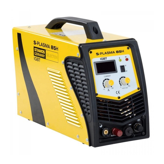
- Seite 5 LEGENDE: POWERSANZEIGE = Wenn man die Maschine einschaltet, geht dieses Licht an. An- / Ausschalter Stromregler: LED – Display: CURRENT = Hauptstrom einstellbar. Zeigt die aktuelle Amperestärke an. 5.+6. Überlastung / Störfall LED: Bei folgenden zwei Situationen geht die Lampe an: Anschlüsse für den Plasmabrenner: Die hohe Energiedichte des Plasmalichtbogens erlaubt eine hohe a) Wenn die Maschine eine Fehlfunktion hat und nicht betrieben...
- Seite 6 Erdung: 2T/4T = Auswahlschalter Hinter jedem Schweißgerät befindet sich eine Schraube und eine Markierung, um die erforderliche Erdung vorzunehmen. Vor Bedienung ist es notwendig die Schale des Schweißgerätes mittels eines Kabels, dessen POST FLOW = Mit diesen Knopf können Sie die Gasnachlaufzeit Einschnitt nicht kleiner sein darf als 6mm, mit der regeln.
- Seite 7 Anschlussschema S-Plasma 55H S-PLASMA 55 H VORDERANSICHT RÜCKANSICHT Stromkabel Luftkompressor Druckminderer an Kompressor Gehäuseabsicherung IGbT Ein Bipolartransistor mit isolierter Gate-Elektrode (english Insulated Gate Bipolar Transistor, kurz IGBT) Massekabel ist ein Halbleiterbauelement, das zunehmend in der Leistungselektronik verwendet wird, da es Vorteile des Bipolartransistors (z.B.
-
Seite 8: Zubehör Bei Plasmaschneidern
Zubehör bei Plasmaschneidern S-PLASMA 85H | S-PLASMA 85CNC VORDERANSICHT RÜCKANSICHT 1. Masseklemme 2. Plasmabrenner 20. Nur für das Modell S-PLASMA 85CNC NETZANSCHLUSS FÜR S-PLASMA 85H / S-PLASMA 85CNC Ein Bipolartransistor mit isolierter Gate-Elektrode IGbT (english Insulated Gate Bipolar Transistor, kurz IGBT) ist ein Halbleiterbauelement, das zunehmend in der STARKSTROM = Diese Geräte arbeiten mit einem Leistungselektronik verwendet wird, da es Vorteile des... -
Seite 9: Cnc Anschluss S-Plasma 85Cnc
Anschluss S-Plasma 85H + 125H / 85CNC + 125CNC Technische Details Netzanschlussplan S-Plasma S-Plasma 85H S-Plasma 125H Die gelb-grüne Ader ist für den Schutzlei- CNC ANSCHLUSS CNC CONNECTION PODŁĄCZENIE CNC teranschluss PE vorgesehen. Die drei Phasen S-Plasma 85CNC* S-Plasma 125CNC* (schwarz, braun und blau) können beliebig an Eingangsspannung 230V... -
Seite 10: Installation
Bedienung Installation Schalten Sie den Einschalter auf dem hinteren Paneelfeld ein, die Kontrollleuchte geht an und der aktuelle Strom wird angezeigt. 1.Jeder Plasmaschneider ist mit einem Stromkabel ausgestattet und entsprechend Stellen Sie den Gasdruck entsprechen den Anforderungen ein und öffnen Sie das der Eingangsspannung des Plasamschneiders, muss es mit der entsprechenden Kompressionsventil. - Seite 11 S-PLASMA 125H | S-PLASMA 125CNC INSTANDSETZUNG A. Entpackung Entpacken Sie alle Sachen aus der Verpackung und versichern Sie sich, dass Sie alle Ge- genstände, die auf der Verpackungsliste aufgelistet sind, erhalten haben. B. Arbeitsumgebung Stellen Sie sicher, dass der Arbeitsbereich gut belüftet ist. Das Gerät wird durch einen Axiallüfter gekühlt, der einen Luftfluss durch das hintere Bedienteil über der Elektronik bereitstellt.
-
Seite 12: Wartung
A. Vorgang des Pistolenlaufbaus 2. Wöchentliche Maßnahmen Stellen Sie die Pistole mit der Schutzkappe nach oben zeigend auf, und drehen Überprüfen Sie, ob die Lüftung einwandfrei funktioniert Blasen oder saugen Sie Staub Sie die Schutzkappe, von der Pistole ab. (Schutzkappe hält die Spitze, den Keramikdre- oder Dreck von der ganzen Maschine, inklusive des Luftfilter ab. - Seite 13 Ce mode d‘emploi comprend les descriptions, les instructions d‘emploi et les processus d‘entretien fondamentaux pour les découpeurs plasma S-Plasma 85H/125H Stamos Germany. Étudiez ces instructions d‘emploi en détail. Une compréhension complète des caractéristiques et des capacités de l‘appareil en garantit une application correcte.
- Seite 14 Ne découpez pas des récipients fermés tels que des réservoirs ou ou nettoyage de la torche. des fûts • Mettre l’appareil hors-tension avant de l’installer ou isolez-vous de la pièce d’ouvrage et du sol en utilisant un tapis d’isolation sec. Branchez le cordon d’alimentation dans une prise électrique à...
- Seite 15 Les PROJECTIONS peuvent engendrer des blessures graves. rayon du faisceau de plasma. Indication! Cette machine est conçue pour utiliser uniquement l‘air comprimé en tant Des étincelles et du métal incandescent sont projetées lors la soudure. que „gaz“. Les ÉTINCELLES peuvent entraîner des blessures. Régulation du courant •...
- Seite 16 Indicateur de surcharge / incident: GAZ/raccordement pour l’air L‘indicateur s‘allume dans les deux situations suivantes: a) Lorsque la machine est en panne. b) Lorsque l‘appareil dépasse la limite du facteur de marche, le mode de protection s‘active et la machine s‘arrête. C‘est-à-dire que l‘appareil n‘est plus en marche afin de rétablir le contrôle de la température après une surchauffe.
-
Seite 17: Face Avant
2T/4T = Interrupteur de sélection Connecteur pour CNC S-PLASMA 55 H POST FLOW = avec ce bouton, vous pouvez régler la durée du temps de post gaz. FACE AVANT FACE ARRIÈRE TEST GAZ = protéger. U.V LED = Under Voltage LED, sous tension. Si la tension tombe à moins de 330V, la LED s‘allume O.V LED = Over voltage LED, surtension. -
Seite 18: Face Avant Face Arrière
Accessoires pour découpeur plasma S-PLASMA 85H | S-PLASMA 85CNC FACE AVANT FACE ARRIÈRE 1. Câble de masse 2. Torche plasma 20. Pour le modèle S-PLASMA 85CNC RACCORDEMENT SECTEUR POUR S-PLASMA 85H / S-PLASMA Le transistor bipolaire à grille isolée (de l‘anglais Insulated IGbT 85CNC Gate Bipolar Transistor - IGBT) est un dispositif semi-... -
Seite 19: Détails Techniques
Détails techniques CNC ANSCHLUSS Raccordement S-Plasma 85H + 125H / 85CNC + 125CNC CNC CONNECTION PODŁĄCZENIE CNC S-Plasma 55H S-Plasma 85H S-Plasma 125H Plan de raccordement au secteur S-PLASMA 125CNC | Plasma Cutter CNC S-PLASMA 85CNC | Plasma Cutter CNC... - Seite 20 Installation Utilisation Actionnez l‘interrupteur sur le panneau arrière, la lumière de contrôle s‘allume et la 1. Chaque découpeur plasma est équipé d‘un câble électricité et doit être con- valeur du courant actuel est indiquée. necté à une alimentation en courant conforme à la tension d‘entrée de l‘appareil. Ajustez conformément la pression du gaz et ouvrez la valve de compression.
-
Seite 21: Mise En Fonctionnement
S-PLASMA 125H | S-PLASMA 125CNC MISE EN FONCTIONNEMENT A. Déballage Déballez chaque pièce de la boîte et assurez-vous que vous avez bien toutes les pièces présentes sur la liste d‘emballage. B. Espace de travail Assurez-vous que votre aire de travail soit bien ventilée. L‘appareil est refroidi grâce à... -
Seite 22: Entretien
A. Assemblage de la torche 2. Entretien hebdomadaire Inclinez la torche avec son capuchon de protection vers le haut et dévissez la buse Vérifiez que le flux d‘air fonctionne normalement. Aspirez toute saleté ou poussière de protectrice du pistolet. (Le capuchon de protection maintient la tuyère, le diffuseur la machine dans sa totalité... - Seite 23 Niniejsza instrukcja obsługi zawiera opisy, instrukcje obsługi i zasadnicze procedury konserwacyjne dotyczące przecinarki plazmowej S-Plasma 85H/125H firmy Stamos Germany. Należy w sposób wyczerpujący zapoznać się z niniejszą instrukcją obsługi. Całkowite zrozumienie właściwości i możliwości zastosowania urządzenia zapewnia prawidłowe jego zastosowanie.
- Seite 24 Nie należy ciąć zamkniętych pojemników takich jak np. zbiorniki lub powiednio od przedmiotu i / lub podłoża poprzez stosowanie suchych mat izola- naczynia cyjnych. • Należy sprawdzić i upewnić się, że drut uziemiający kabla zasilającego jest prawidło- Należy podłączyć kabel roboczy z gniazdkiem znajdującym się w pobliżu miejsca robo- wo połączony ze stykiem uziemienia lub wtyk kabla jest połączony z prawidłowo czego, tak aby uniknąć...
- Seite 25 EKSPLODUJĄCE CZĘSCI mogą prowadzić do okaleczeń. liwiają wyprowadzanie stałego przepływu gazu ochronnego. Ciśnienie tego przepływu Iskry oraz części metalowe odpryskują od powierzchni spawania. gazu umożliwia kontrolowanie promienia strumienia plazmy. Wskazówka! Maszyna przewidziana jest do tylko do zastosowania sprężonego powie- LATAJĄCE ISKRY mogą powodować okaleczenia. trza jako gazu.
- Seite 26 LEGENDA: WSKAŹNIK ZASILANIA = po włączeniu maszyny zapala się ta kontrolka. Włącznik/ wyłącznik Regulator prądu CURRENT = Możliwość regulacji prądu głównego Wyświetlacz LED = wyświetlą bieżącą wartość natężenia prądu. 5.+6. Przeciążenie / awaria = lampka zapala się w przypadku wystąpienia Przyłącze uchwytu (palnika) plazmowego: dwóch Wysoka gęstość...
- Seite 27 Uziemienie: 2T/4T przełącznik wyboru Z tyłu każdego urządzenia do spawania znajduje się śruba oraz informacja o konieczności zapewnienia odpowiedniego uziemienia. Przed rozpoczęciem obsługi konieczne jest uziemienie obudowy spawarki z użyciem kabla, którego POST FLOW = Za pomocą tego przycisku można regulować czas przekrój nie może być...
-
Seite 28: Widok Z Tyłu
SCHEMAT PODŁĄCZENIA S-Plasma 55H S-PLASMA 55 H WIDOK Z PRZODU WIDOK Z TYŁU Przewód zasilający Sprężarka powietrza Reduktor ciśnienia sprężarki Uziemienie obudowy IGbT Tranzystor bipolarny z izolowaną bramką elektrody (z ang. Insulated Gate Bipolar Transistor, w skrócie IGBT) Przewód masowy jest elementem półprzewodnikowym, który stosuje się... -
Seite 29: Widok Z Przodu
Akcesoria przecinarek plazmowych S-PLASMA 85H | S-PLASMA 85CNC WIDOK Z PRZODU WIDOK Z TYŁU 1. Zacisk masy 2. Palnik plazmy 20. Tylko dla modelu S-PLASMA 85CNC PRZYŁĄCZE SIECIOWE S-PLASMA 85H / S-PLASMA 85CNC Tranzystor bipolarny z izolowaną bramką elektrody (z IGbT ang. -
Seite 30: Cnc Anschluss Cnc Connection
Podłączenie S-Plasma 85H + 125H / 85CNC + 125CNC Szczegółowe dane techniczne CNC ANSCHLUSS CNC CONNECTION PODŁĄCZENIE CNC Podłączenie do sieci S-Plasma S-Plasma S-Plasma Żółto-zielona żyła jest przewidziana 85H oraz 125H oraz S-PLASMA 125CNC | Plasma Cutter CNC S-PLASMA 85CNC | Plasma Cutter CNC podłączenia przewodu ochronnego PE. - Seite 31 Instalacja Obsługa Należy włączyć włącznik na tylnym panelu, kontrolka się uruchamia i podawana jest aktualna wartość prądu. 1. Każda przecinarka plazmowa jest wyposażona w kabel zasilania i musi zostać Należy ustawić ciśnienie gazu zgodnie z wymogami i otworzyć zawór kompresyj- podłączona z odpowiednim źródłem zasilania zgodnie z napięciem wejściowym przecinarki plazmowej.
- Seite 32 S-PLASMA 125H | S-PLASMA 125CNC URUCHOMIENIE A. Rozpakowanie Należy wypakować wszystkie elementy z opakowania i upewnić się, że dostarczone zostały wszystkie przedmioty ujęte w liście dostawy. B. Otoczenie robocze Upewnić się, że obszar roboczy jest dobrze wietrzony. Urządzenie jest chłodzone z wykorzystaniem wentylatora osiowego, który dostarcza strumień...
- Seite 33 A. Montaż uchwytu plazmowego (palnika) 2. Czynności cotygodniowe Należy ustawić uchwyt plazmowy osłoną ochronną w górę i odkręcić ją. (Osłona utrzy- Należy sprawdzić, czy wentylacja prawidłowo funkcjonuje. Należy usunąć lub odkurzyć muje końcówkę, obrotowy pierścień ceramiczny oraz elektrodę). Usunąć końcówkę, pył...
-
Seite 34: Important Safety Information
CAUTION: used with the safety alert symbol, indicates a hazardous situation which, if not avoided, could result in minor or moderate injury. S-PLASMA 55H | S-PLASMA 85H S-PLASMA 125H | S-PLASMA 85CNC NOTICE: is used to address practices not related to personal injury. -
Seite 35: Personal Safety
• Double insulated tools are equipped with a polarized plug (one blade is wider • Disconnect the Power Cord Plug from the power source before making any adju- than the other). This plug will fit in a polarized outlet only one way. If the plug does stments, changing accessories, or storing the tool. - Seite 36 that can catch and hold molten metal or sparks. the operation and air quality and make recommendations for the specific welding • Keep clothing free of grease, oil, solvents, or any flammable substances. Wear dry, or cutting situation. insulating gloves and protective clothing. •...
- Seite 37 Heat protection The thermal protection circuit takes action when the device exceeds the duty cycle. POWER INDICATOR: This indicator lights up after turning the machine This means stopping the machine. Duty Cycle The duty cycle is the percentage of the operating time (measured in minutes) of a 10-minute period in which the machine is used continuously in normal temperature conditions.
- Seite 38 Grounding: At the back of each welder there is 4T/2T selection button a screw and a label to provide the necessary grounding. Before operating the unit it is necessary to ground the shell of the welding apparatus by means of a cable with not less than 6 mm diameter, in order to prevent potential POST FLOW = setting the time of the air flow after the cutting.
-
Seite 39: Rear View
General diagram of S-Plasma 55H connection S-PLASMA 55 H FRONT VIEW REAR VIEW Power supply cord Air compressor Pressure regulator Cover earthing IGbT IGBT: A bipolar transistor with insulated gate electrode (insulated Mass cable gate bipolar transistor, IGBT) is a semiconductor that is increasingly used in power electronics, as the bipolar transistors offer certain advantages (e.g. -
Seite 40: Front View
Plasma cutters accessories S-PLASMA 85H | S-PLASMA 85CNC FRONT VIEW REAR VIEW 1. Grounding clamp cable 2. Plasma torch with cable 20. Only for S-PLASMA 85CNC POWER SUPPLY FOR S-PLASMA 85H / S-PLASMA 85CNC A bipolar transistor with insulated gate electrode (insulated IGbT gate bipolar transistor, IGBT) is a semiconductor that is increasingly used in power electronics, as the bipolar... - Seite 41 S-Plasma 85H + 125H / 85CNC + 125CNC connection. Detailed technical parameters: Power supply. S-Plasma S-Plasma 85H S-Plasma 125H The yellow-green wire is used as a PE protec- CNC ANSCHLUSS CNC CONNECTION PODŁĄCZENIE CNC tive wire connector. The three phases (black, S-Plasma 85CNC* S-Plasma 125CNC* brown and blue) can be freely connected to L1,...
-
Seite 42: Cable Connections
Cable connections S-PLASMA 125H | S-PLASMA 125CNC 1. Each plasma cutter is equipped with a main power cable, which is responsible for providing current and voltage to the device and it must be connected to the suitable power source according to plasma cutter input voltage. 2. - Seite 43 INITIATING OPERATION INSTRUCTIONS FOR USE A. Unpacking A. The beginning Unpack all the items out of the box and make sure that you have received all items Turn the power switch to „ON“. Take up a position at the unit in which you can easily listed on the packing list.
-
Seite 44: Maintenance
MAINTENANCE Check the pistol for wear damage, cracks or exposed wire sections. Replace or repair any such defects before using the device. A heavily worn pistol tip/nozzle contributes to the reduction of speed, voltage drops and crooked cuts. An indication of a worn pistol tip/nozzle is an elongated or oversized nozzle opening. -
Seite 45: Umwelt- Und Entsorgungshinweise
Umwelt- und Entsorgungshinweise Hersteller an Verbraucher Sehr geehrte Damen und Herren, gebrauchte Elektro- und Elektronikgeräte dürfen gemäß europäischer Vorgaben [1] nicht zum unsortierten Siedlungsabfall gegeben werden, sondern müssen getrennt erfasst werden. Das Symbol der Abfalltonne auf Rädern weist auf die Notwendigkeit der getrennten Sammlung hin.