Inhaltsverzeichnis
Werbung
Verfügbare Sprachen
Verfügbare Sprachen
Quicklinks
SCOPO DEL MANUALE
Questo manuale è stato redatto dal costruttore ed è parte integrante del prodotto.
In esso sono contenute tutte le informazioni necessarie per:
• la corretta sensibilizzazione degli installatori alle problematiche della sicurezza;
• la corretta installazione del dispositivo;
• la conoscenza approfondita del suo funzionamento e dei suoi limiti;
• il corretto uso in condizioni di sicurezza;
La costante osservanza delle indicazioni fornite in questo manuale, garantisce la sicurezza dell'uomo, l'economia
di esercizio e una più lunga durata di funzionamento del prodotto.
Al fi ne di evitare manovre errate con il rischio di incidenti, è importante leggere attentamente questo manuale,
rispettando scrupolosamente le informazioni fornite.
Le istruzioni, i disegni, le fotografi e e la documentazione contenuti nel presente manuale sono di proprietà
APRIMATIC S.p.a. e non possono essere riprodotti in alcun modo, né integralmente, né parzialmente.
Il logo "APRIMATIC" è un marchio registrato di APRIMATIC S.p.a.
PURPOSE OF THE MANUAL
This manual was drawn up by the manufacturer and is an integral part of the product.
It contains all the necessary information:
• to draw the attention of the installers to safety related problems
• to install the device properly
• to understand how it works and its limits
• to use the device under safe conditions
Strict observance of the instructions in this manual guarantees safe conditions as well as efficient operation and
a long life for the product.
To prevent operations that may result in accidents, read this manual and strictly obey the
instructions provided.
Instructions, drawings, photos and literature contained herein are the exclusive property of the
manufacturer and may not be reproduced by any means.
The "Aprimatic" logo is a trademark registered by Aprimatic S.p.A.
BUT DU MANUEL
Ce manuel a été rédigé par le constructeur et fait partie intégrante du produit.
Il contient toutes les informations nécessaires pour :
• sensibiliser les installateurs aux problèmes liés à la sécurité ;
• installer le dispositif de manière correcte ;
• connaître le fonctionnement et les limites du dispositif ;
• utiliser correctement le dispositif dans des conditions de sécurité optimales ;
Le respect des indications fournies dans ce manuel garantit la sécurité personnelle, une économie de fonctionnement
et une longue durée de vie du produit.
Afi n d'éviter des opérations incorrectes et de ne pas risquer des accidents sérieux, lire attentivement ce manuel et
respecter scrupuleusement les informations fournies.
Les instructions, les dessins, les photos et la documentation contenus dans ce manuel sont la propriété d'APRIMATIC
S.p.A. et ne peuvent être reproduits sous aucune forme, ni intégralement, ni partiellement.
Le logo « Aprimatic » est une marque déposée par Aprimatic S.p.A.
ZWECK DES HANDBUCHS
Dieses Handbuch wurde vom Hersteller verfasst und ist ein ergänzender Bestandteil des Produkts.
Es enthält alle nötigen Informationen für:
• die Sensibilisierung der Monteure für Fragen der Sicherheit;
• die vorschriftsmäßige Installation der Vorrichtung;
• die umfassende Kenntnis ihrer Funktionsweise und ihrer Grenzen;
• die vorschriftsmäßige und sichere Benutzung.
Die Beachtung der in diesem Handbuch enthaltenen Anweisungen gewährleistet die Sicherheit der Personen, den
wirtschaftlichen Betrieb und eine lange Lebensdauer des Produkts.
Zur Vermeidung von Fehlbedienung und somit Unfallgefahr dieses Handbuch aufmerksam durchlesen und die
Anweisungen genau befolgen.
Die Anleitungen, Zeichnungen, Fotos und Dokumentationen in diesem Handbuch sind Eigentum von APRIMATIC
S.p.A. und dürfen in keiner Weise ganz oder teilweise reproduziert werden.
Das Logo „Aprimatic" ist ein eingetragenes Warenzeichen der Aprimatic S. p. A.
OBJETO DEL MANUAL
Este manual ha sido redactado por el constructor y forma parte integrante del producto.
El mismo contiene todas las informaciones necesarias para:
• la correcta sensibilización de los instaladores hacia los problemas de la seguridad
• la correcta instalación del dispositivo
• el conocimiento en profundidad de su funcionamiento y de sus límites
• el correcto uso en condiciones de seguridad
La constante observación de las indicaciones suministradas en este manual, garantiza la seguridad del hombre,
la economía del ejercicio y una mayor duración de funcionamiento del producto.
Con el fi n de evitar maniobras equivocadas con riesgo de accidente, es importante leer atentamente este manual,
respetando escrupulosamente las informaciones suministradas.
Las instrucciones, los dibujos, las fotografías y la documentación que contiene este manual son propiedad de
APRIMATIC S.p.a. y no pueden ser reproducidas en ninguna manera, ni integral ni parcialmente.
El logotipo "Aprimatic" es una marca registrada de Aprimatic S. p. A.
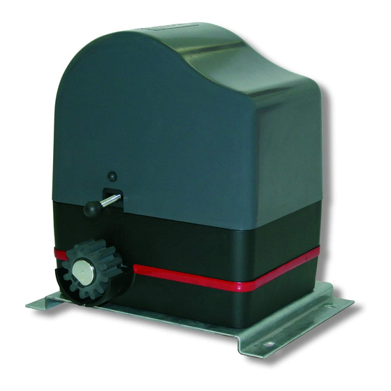
ONDA 624
Motoriduttore 24V per cancello scorrevole
Gearmotor 24V for sliding gate
Motoréducteur pour portail coulissant
Getriebemotor 24V für Schiebetor
Motorreductor 24V para cancela corredera
Istruzioni di installazione meccanica Uso e
Mechanical installation, Use and Mainte-
Notice d'installation mécanique, d'Utilisation
Anleitung für die mechanische Installation,
Instrucciones para la instalación mecánica,
el uso y el mantenimiento
Manutenzione
nance instructions
et d'Entretien
Gebrauch und Wartung
Werbung
Kapitel
Inhaltsverzeichnis
Fehlerbehebung

Verwandte Anleitungen für Aprimatic ONDA 624


Inhaltszusammenfassung für Aprimatic ONDA 624
- Seite 1 Afi n d’éviter des opérations incorrectes et de ne pas risquer des accidents sérieux, lire attentivement ce manuel et respecter scrupuleusement les informations fournies. Les instructions, les dessins, les photos et la documentation contenus dans ce manuel sont la propriété d’APRIMATIC S.p.A. et ne peuvent être reproduits sous aucune forme, ni intégralement, ni partiellement.
-
Seite 2: Inhaltsverzeichnis
CANCELLI AD ANTE SCORREVOLI ONDA 624 SOMMARIO NORME DI SICUREZZA E OBBLIGHI DELL’INSTALLATORE AVVERTENZE PER L’UTILIZZATORE TERMINOLOGIA E SIMBOLI ADOTTATI NEL MANUALE 1. Descrizione del prodotto Uso previsto e Campo d’impiego Rischi residui Dati tecnici Dimensioni d’ingombro 2. Operazioni preliminari Verifica della fornitura Controlli preliminari: struttura del Cancello;... -
Seite 3: Norme Di Sicurezza E Obblighi Dell'installatore
CANCELLI AD ANTE SCORREVOLI ONDA 624 NORME DI SICUREZZA E OBBLIGHI DELL’INSTALLATORE Per lavorare nel pieno rispetto delle norme di sicurezza occorre: • indossare indumenti di protezione a norma di legge (scarpe antinfortunistiche, occhiali di protezione, guanti ed elmetto); • non indossare articoli di abbigliamento che possano impigliarsi (cravatte, bracciali, collane, ecc.). -
Seite 4: Descrizione Del Prodotto
Cautela È vietato utilizzare il prodotto per scopi impropri o comunque diversi da quelli previsti. È vietato manomettere o modifi care il prodotto. Il prodotto deve essere installato solo con accessori APRIMATIC. Rischi residui Attenzione Durante l’apertura del cancello la zona in cui opera l’ingranaggio dell’attuatore è pericolosa per chiunque si avvicini incautamente con le mani o qualsiasi altra parte del corpo. -
Seite 5: Operazioni Preliminari
CANCELLI AD ANTE SCORREVOLI ONDA 624 Fig.5 Pos. Descrizione Q.tà Attuatore Piastra di fondazione Tirafondo + dadi + rosetta 4 + 8 + 4 Chiave di sblocco Blocchetto fi lettato + vite + rosetta 4 + 4 + 4 Piastrino fi necorsa + viti... -
Seite 6: Fissaggio Dell'attuatore
CANCELLI AD ANTE SCORREVOLI ONDA 624 FISSAGGIO DELL’ATTUATORE L’attuatore può essere fi ssato al suolo: A- tramite la piastra di fondazione con 4 tirafondi di ancoraggio, cementati (kit di fondazione). oppure: B- direttamente con tasselli a espansione o chimici se il suolo è... -
Seite 7: Fissaggio Mediante Tasselli A Espansione
CANCELLI AD ANTE SCORREVOLI ONDA 624 • Sbloccare l’attuatore (Fig.12). Fig.12 • Allentare la vite di fi ssaggio del carter di protezione dell’attuatore e rimuoverlo (Fig.13). • Posizionare l’attuatore sulla piastra di fi ssaggio e ancorarlo mediante le apposite viti e rosette (Fig.14-rif.A). -
Seite 8: Fissaggio Asta Cremagliera
La cremagliera adatta al motoriduttore ONDA 624 è in materiale termoplastico stampato e viene fornita da Aprimatic. Ha un’anima in acciaio e può spostare ante fi no a 500 kg. Si monta con facilità senza bisogno di saldature. Per ante oltre 500 kg utilizzare la cremagliera in acciaio. -
Seite 9: Cremagliera In Acciaio Zincato
CANCELLI AD ANTE SCORREVOLI ONDA 624 • Procedere poi con il fi ssaggio dei successivi componenti della cremagliera incastrandoli come indicato (Fig.23). Attenzione Verifi care sempre, con una dima (Fig.24 A) che il passo, nei punti di giunzione fra le aste, rimanga costante. -
Seite 10: Fissaggio Piastrini Finecorsa
CANCELLI AD ANTE SCORREVOLI ONDA 624 Fissaggio piastrini fi necorsa L’attuatore è dotato di un fi necorsa elettromeccanico con asta a molla, il cui azionamento è determinato da due piastrini metallici da montare sulla cremagliera in modo da impegnare l’asta del finecorsa in prossimità delle... -
Seite 11: Note Per L'utente
CANCELLI AD ANTE SCORREVOLI ONDA 624 NOTE PER L'UTENTE Fig.32 Manovra di emergenza (sblocco) In caso di mancanza di corrente, sbloccare l’attuatore girando la chiave in senso orario e aprire la leva (Fig.32) per aprire il cancello manualmente. Al termine dell’operazione ribloccare l’attuatore, quindi far scorrere leggermente il cancello in un... - Seite 12 Index INDEX SAFETY STANDARDS AND INSTALLER OBLIGATIONS NOTES FOR USERS TERMINOLOGY AND SYMBOLS USED IN THIS MANUAL 1. Product technical features Destined use and Working range Residual risks Technical data Overall dimensions 2. Preliminary operations Supply inspection Preliminary checks: gate structure; guides; rails and sliding wheels 3.
-
Seite 13: Safety Standards And Installer Obligations
Premises / Safety rules SAFETY STANDARDS AND INSTALLER OBLIGATIONS Installers must proceed as follows to conform with safety standards: • wear protective clothing (accident-prevention footwear, goggles, gloves and helmet); • do NOT wear clothing or jewellery that may become trapped (ties, bracelets, necklaces, etc.). A motorised gate is a machine and as such must be installed in accordance with health and safety standards and legislation. -
Seite 14: Product Technical Features
ONDA624 operator is designed to automate the movement of max. 600 Kg sliding gates for residential-use, or of max. 400 kg for condominium-use. Any other use whatsoever is not authorised by Aprimatic. Caution It is forbidden to use the product improperly or for different aims than those intended. -
Seite 15: Preliminary Operations
Preliminary operations Fig.5 Pos. Description Q.ty Operator Foundation plate Log bolts + nuts + washer 4 + 8 + 4 Release key Threaded block + screw + washer 4 + 4 + 4 Limit switch plate + screws 2 + 4 PRELIMINARY OPERATIONS Supply inspection Ensure that the package contains all the components listed... -
Seite 16: Installation
Installation FITTING THE OPERATOR Two methods for fi xing the operator to the ground: A- by means of the foundation slab with 4 anchor log bolts, sunk in cement (the foundation kit). B- directly fi xed to the terrain using screws or chemical anchors. -
Seite 17: Fixing With Screw Anchors
Installation • Release the operator (Fig.12). Fig.12 • Loosen the fi xing screws of the protective casing of the operator and remove the casing (Fig.13). • Position the operator on the fi xing slab and anchor in place using the supplied screws and washers (Fig.14-Ref.A). •... -
Seite 18: Fixing The Bar Rack
Installation Fixing the bar rack The rack for the ONDA 624 gearmotor is a moulded thermoplastic material supplied by Aprimatic. The rack has a steel core and can move gates of up to 500 kg. It can be easily mounted without the need for any soldering or welding. - Seite 19 Installation • Proceed by fi xing the other components of the rack as shown (Fig.23). Warning Always check with a template (Fig.24 A) that the pitch between the bar linkages is kept even. If the fi t is imperfect and it is impossible to maintain the correct pitch, then you need to adjust them.
-
Seite 20: Fixing The Limit Switch Plates
Installation FixIng the limit switch plates The actuator has an electromechanical limit switch with a spring rod. The limit switch is tripped by two metal plates that must be fi tted on the rack in such a way as to engage the limit switch rod when the gate is near the fully open and fully closed positions. -
Seite 21: Notes For Users
PLEASE GIVE A COPY OF THIS PAGE TO THE USER Aprimatic S.p.A. via Leonardo da Vinci, 414 40059 Villa Fontana di Medicina - Bologna - Italia Telf. +39 051 6960711 - fax +39 051 6960722 info@aprimatic.com - www.aprimatic.com - 21 -... - Seite 22 Table des matières TABLE DES MATIÈRES NORMES DE SÉCURITÉ ET OBLIGATIONS DE L’INSTALLATEUR MISE EN GARDE POUR L’UTILISATEUR TERMINOLOGIE ET SYMBOLES UTILISÉS DANS LE MANUEL 1. Caractéristiques du produit Utilisation prévue et Secteur d’emploi Risques résiduels Données techniques Dimensions d’ encombrement 2.
-
Seite 23: Mises En Garde Pour L'utilisateur
Avant propose / Normes de sécurité • Les emballages ne doivent pas être jetés dans la nature, mais doivent être éliminés en conformité avec les normes et les règlementations en vigueur. • Avant de commencer l’installation, vérifi er que le produit et l’emballage ne sont pas endommagés. •... -
Seite 24: Caractéristiques Du Produit
• Il est interdit d’utiliser le produit pour des buts différents de ceux prévus ou abusifs. • Le produit doit être installé seulement avec des accessoires APRIMATIC. Risques résiduels Attention Pendant l’ouverture du portail la zone où l’engrenage de l’actionneur travaille est dangereuse pour n’importe qui approche imprudemment ses mains ou une partie quiconque de son corps. -
Seite 25: Opérations Préliminaires
Opérations préliminaires Fig.5 Pos. Descriptione Q.té Actionneur Plaque de fondation Tire-fonds + ecrous + rondelle 4 + 8 + 4 Clé de dévérrouillage Bloc fi leté + vis + rondelle 4 + 4 + 4 Plaque de fi n de course + vis 2 + 4 OPÉRATIONS PRÉLIMINAIRES Vérifi... -
Seite 26: Fixation De L'actionneur
Montage FIXATION DE L’ACTIONNEUR On peut fi xer l’actionneur au sol de deux façons: A- par la plaque de fondation avec 4 tire-fonds d’ancrage, immergé dans le béton (kit de fondation). ou bien: B- directement par des chevilles expansibles ou chimiques si le sol est assez consistant et plat. -
Seite 27: Fixation Par Des Chevilles Expansibles
Montage • Déverrouiller l’actionneur (Fig.12). Fig.12 • Desserrer la vis de fi xation du carter de protection de l’actionneur et enlever-le (Fig.13). • Positionner l’actionneur sur la plaque de fi xation et le fi xer par les vis et les rondelles fournies (Fig.14-réf.A). •... -
Seite 28: Fixation De La Tige De La Cremaillere
Montage Fixation de la tige de la cremaillere La crémaillère indiquée pour le motoréducteur ONDA 624 est en matériau thermoplastique moulé et elle est fournie par Aprimatic. Elle possède une âme en acier et peut déplacer des vantaux jusqu’à 500 kg. On la monte facilement sans besoin de soudures. - Seite 29 Montage • Puis fi xer les composants successifs de la crémaillère en les encastrant comme il est indiqué (Fig.23). Attention Vérifi er toujours, par un gabarit (Fig.24 A), que le pas, dans les points de jonction entre les tiges, reste constant. •...
-
Seite 30: Fixation Des Plaques De Fin De Course
Montage FIxation des plaques de fi n de course L’opérateur est équipé d’un fi n de course électromécanique avec tige à ressort dont l’actionnement dépend de deux plaques métalliques montées sur la crémaillère de façon à engager la tige du fi n de course à proximité des positions d’ouverture complète et de fermeture complète du portail. -
Seite 31: Remarques Pour L'utilisateur
VEUILLEZ DONNER UNE COPIE DE CETTE PAGE À L’UTILISATEUR Aprimatic S.p.A. via Leonardo da Vinci, 414 40059 Villa Fontana di Medicina - Bologna - Italia Telf. +39 051 6960711 - fax +39 051 6960722 info@aprimatic.com - www.aprimatic.com - 31 -... -
Seite 32: Sicherheitsvorschriften Und Pflichten Des Installateurs
Inhaltsverzeichnis INHALTSVERZEICHNIS SICHERHEITSVORSCHRIFTEN UND PFLICHTEN DES INSTALLATEURS HINWEISE FÜR DEN BENUTZER IM TEXT VERWENDETE BEGRIFFE UND SYMBOLE 1. Beschreibung des Antriebs Vorgesehene Verwendung und Einsatzbereich Restrisiken Technische Daten Abmessungen 2. Vorbereitung für die Installation Überprüfung der Transportverpackung Betriebsvorbereitende Kontrollen: Torkonstruktion; Führungsleiste und Rollen 3. -
Seite 33: Hinweise Für Den Benutzer
Einleitung / Sicherheitsvorschriften • Lesen Sie diese Anleitung aufmerksam durch, bevor Sie mit der Installation des Produkts beginnen. • Eine nicht korrekte Installation kann eine Gefahrenquelle darstellen. • Die Verpackungen dürfen nicht einfach weggeworfen, sondern müssen gemäß den geltenden Gesetzen und Vorschriften entsorgt werden. -
Seite 34: Technische Eigenschaften / Betriebsvorbereitende Arbeitsvorgänge
Der Antrieb ONDA624 wurde für die Automatisierung von Schiebetoren mit max. Gewicht 600 kg für residentiellen Einsatz entwickelt. Der Einsatzbereich ist auf Tore für Wohnanlagen bis 400Kg beschränkt. Jeder andere Einsatz ist nicht von Aprimatic S.p.A. genehmigt. Vorsicht Der Einsatz des Produktes für andere als die vorgesehenen oder für unsachgemäße Zwecke ist untersagt. -
Seite 35: Betriebsvorbereitende Arbeitsvorgänge
Betriebsvorbereitende Arbeitsvorgänge BETRIEB SVORBEREITENDE Abb.5 Fig.5 ARBEITSVORGÄNGE Überprüfung der Transportverpackung Überprüfen Sie, ob die Originalverpackung alle in Abb.5 angeführten Bauteile enthält und kontrollieren Sie, ob diese unbeschädigt sind. Überprüfen Sie ferner, ob die Modellbezeichnung des Antriebs auf der Verpackung der auf dem Schild des Getriebemotors entspricht (Abb.4). -
Seite 36: Installation
Installation BEFESTIGUNG DES ANTRIEBS Der Antrieb kann auf folgende Weise am Boden befestigt werden: A- mit der Fundamentschablone und 4 Ankerbolzen, die in Zement gebettet sind (Fundamentsatz); oder: B- mit chemischen oder mit Spreizdübeln, soweit die Konsistenz und die Ebenheit des Bodens dies zulassen. Achtung Andere Montagearten, bei denen die Basis des Motor sich nicht in horizontaler Lage befi... -
Seite 37: Befestigung Mit Spreizdübel
Installation • Den Antrieb entriegeln (Abb.12). Abb.12 • Die Befestigungsschraube der Schutzabdeckung des Antriebs lockern und die Abdeckung abnehmen (Abb.13). • Den Antrieb auf der Befestigungsplatte positionieren und mit den mitgelieferten Muttern und Unterlegscheiben auf der Platte verankern (Abb.14-Pos.A). • Die Höheneinstellung gegenüber dem Boden vornehmen. •... -
Seite 38: Befestigung Regelstange
Installation BEFESTIGUNG REGELSTANGE Abb.18 Die für den Getriebemotor ONDA 624 geeignete Zahnstange besteht aus formgepresstem thermoplastischen Material und wird von Aprimatic geliefert. Sie ist mit einem Stahlkern ausgestattet und kann Torfl ügel bis 500 kg bewegen. Die Zahnstange kann einfach ohne Schweißungen montiert werden. - Seite 39 Installation Verpackung befinden, befestigen. Dabei ist darauf zu Abb.23 achten, diese nicht vollständig anzuziehen und während des Anzugs stets die horizontale Ausrichtung der Stange mit einer Wasserwaage zu kontrollieren. • Dann die Befestigung der nachfolgenden Bestandteile der Zahnstange vornehmen, indem diese wie angegeben eingesetzt werden (Abb.23).
-
Seite 40: Befestigung Der Anschlagplatten
Installation Befestigung der Anschlagplatten Abb.29 Der Antrieb besitzt einen elektromechanischen Endschalter mit Federstange, der von zwei Metallplatten betrieben wird, die auf die Zahnstange montiert werden und die Endschalterstange bei Annäherung an die Torpositionen “Vollständig geöffnet” und Vollständig geschlossen” auslösen. STOP Achtung Um jegliche Quetschgefahr zu vermeiden, nicht die mechanischen Anschläge des Tores als Endanschläge... -
Seite 41: Hinweise Für Den Benutzer
BITTE ÜBERGEBEN SIE DEM BENUTZER EINE KOPIE DIESER SEITE. Aprimatic S.p.A. via Leonardo da Vinci, 414 40059 Villa Fontana di Medicina - Bologna - Italia Telf. +39 051 6960711 - fax +39 051 6960722 info@aprimatic.com - www.aprimatic.com - 41 -... -
Seite 42: Normas De Seguridad Y Obligaciones Del Instalador
Índice ÍNDICE NORMAS DE SEGURIDAD Y OBLIGACIONES DEL INSTALADOR ADVERTENCIA PARA EL USUARIO TÉRMINOS Y SÍMBOLOS UTILIZADOS EN EL MANUAL 1. Características técnicas Uso previsto y Campo de aplicación Peligros residuos Datos técnicos Dimensiones 2. Operaciones preliminares Comprobación embalaje Comprobación preliminares: estructura de la cancela; guías y ruedas 3. -
Seite 43: Términos Y Símbolos Utilizados En El Manual
Prólogo / Normas de seguridad • Una instalación incorrecta puede ser fuente de peligros. • No abandonar los embalajes en el ambiente, eliminarlos según las leyes y los reglamentos en vigor. • Antes de iniciar la instalación comprobar que el producto y el embalaje no están dañados. •... -
Seite 44: Características Técnicas
Precaución Queda prohibido utilizar el producto para fi nes inadecuados o distintos de los previstos. Queda prohibido manipular o modifi car el producto. El producto se debe instalar únicamente con accesorios APRIMATIC. Peligros residuos Atención Durante la apertura de la cancela, la zona en la que funciona el engranaje del actuador es peligrosa para todo aquel que se acerque sin tomar precaución, con las manos o con cualquier otra parte del cuerpo. -
Seite 45: Operaciones Preliminares
Operaciones preliminares Fig.5 Pos. Descripción Ctdad Actuador Placa de cimentación Tirafondo + tuercas + arandela 4 + 8 + 4 Llave de desbloqueo Bloque roscado + tornillo + arandela 4 + 4 + 4 Placa de fi nal de carrera + tornillos 2 + 4 OPERACIONES PRELIMINARES Comprobación embalaje... -
Seite 46: Installación
Installación FIJACIÓN DEL ACTUADOR El actuador se puede fi jar al suelo de dos formas: A- a través de la placa de cimentación y de 4 tirafondos de anclaje, hundidos en el cemento (kit de cimentación). o bien: B- a través de tacos químicos o de expansión si el suelo es lo sufi... -
Seite 47: Fijación Mediante Tacos De Expansión
Installación • Desbloquear el actuador (Fig.12). Fig.12 • Afl ojar el tornillo de fi jación de la cubierta de protección del actuador (Fig.13) y retirar la cubierta. • Colocar el actuador sobre la placa de fi jación y fi jarlo a la placa mediante los tornillos y las arandelas proporcionadas (Fig.14-ref.A). -
Seite 48: Montaje De La Cremallera
Installación Montaje de la barra de la cremallera La cremallera adecuada para el motorreductor ONDA 624 está fabricada en material termoplástico moldeado y es suministrada por Aprimatic. Está provista de un alma de acero y puede mover hojas de hasta 500 kg. Se monta fácilmente sin necesidad de soldadura alguna. -
Seite 49: Cremallera En Acero Galvanizado
Installación siempre la horizontalidad de la barra con un nivelador. • Proceder a continuación a fi jar las demás piezas de la cremallera insertándolas de la forma indicada (Fig.23). Atención Comprobar siempre con una plantilla (Fig.24 A), que el paso es constante en los puntos de acoplamiento entre las barras. -
Seite 50: Fijación De Las Placas Final Carrera
Installación Fijación de las placas fi nal carrera El actuador está provisto de un fi nal de carrera electromecánico con varilla de muelle. Su accionamiento está determinado por dos placas metálicas que se montan sobre la cremallera y que accionan la varilla del fi nal de carrera, cuando se acercan a las posiciones de completamente abierta y STOP completamente cerrada de la cancela. -
Seite 51: Notas Para El Usuario
SE RUEGA ENTREGAR UNA COPIA DE ESTA PÁGINA AL USUARIO Aprimatic S.p.A. via Leonardo da Vinci, 414 40059 Villa Fontana di Medicina - Bologna - Italia Telf. +39 051 6960711 - fax +39 051 6960722 info@aprimatic.com - www.aprimatic.com - 51 -... - Seite 52 Aprimatic S.p.A. via Leonardo da Vinci, 414 40059 Villa Fontana di Medicina - Bologna - Italy tel. +39 051 6960711 - fax +39 051 6960722 info@aprimatic.com - www.aprimatic.com...