
Verwandte Anleitungen für Sentiotec MiniMy


Inhaltszusammenfassung für Sentiotec MiniMy
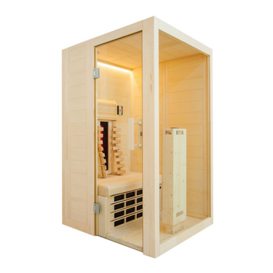
- Seite 1 Infrarotkabine MiniMy 120 x 130 x 202 cm MONTAGE- UND GEBRAUCHSANWEISUNG Deutsch Version 01/18 Ident-Nr. 1-045-570...
-
Seite 2: Inhaltsverzeichnis
2. Wichtige Hinweise zu Ihrer Sicherheit 2.1. Bestimmungsgemäßer Gebrauch 2.2. Sicherheitshinweise 3. Produktbeschreibung 3.1. Lieferumfang MiniMy 3.2. Produktfunktionen 4. Montage der Infrarotkabine MiniMy 4.1. Benötigtes Werkzeug 4.2. Stückliste Infrarotkabine MiniMy 4.3. Montage der Kabine 4.4. Montage der Inneneinrichtung 4.5. Montage Infrarot-Strahler und Wärmeplatte 4.6. -
Seite 3: Zu Dieser Anleitung
Sie sie in der Nähe der Infrarotkabine auf. So können Sie jederzeit Informationen zu Ihrer Sicherheit und zur Bedienung nachlesen. Sie finden diese Montage- und Gebrauchsanweisung auch im Download- bereich unserer Webseite auf www.sentiotec.com/downloads. Symbole in Warnhinweisen In dieser Montage- und Gebrauchsanweisung ist vor Tätigkeiten, von denen eine Gefahr ausgeht, ein Warnhinweis angebracht. -
Seite 4: Wichtige Hinweise Zu Ihrer Sicherheit
Montage- und Gebrauchsanweisung S. 4/40 2. Wichtige Hinweise zu Ihrer Sicherheit Die Infrarotkabine ist nach anerkannten sicherheitstechnischen Regeln gebaut. Dennoch können bei der Verwendung Gefahren entstehen. Befolgen Sie deshalb die folgenden Sicherheitshinweise und die speziellen Warnhinweise in den einzelnen Kapiteln. 2.1. - Seite 5 Montage- und Gebrauchsanweisung S. 5/40 ● Die Kabine darf nicht von Kindern unter 8 Jahren verwendet werden. ● Die Kabine darf von Kindern über 8 Jahren, von Personen mit verringerten psychischen, sensorischen oder mentalen Fähig- keiten und von Personen mit Mangel an Erfahrung und Wissen unter folgenden Bedingungen verwendet werden: –...
-
Seite 6: Produktbeschreibung
Montage- und Gebrauchsanweisung S. 6/40 3. Produktbeschreibung 3.1. Lieferumfang MiniMy ● 1x 1-045-570 / Infrarotkabine MiniMy ● 1x 1-037-357 / Leistungsteil wave.com4 Infra ● 1x 1-012-222 / Bedienteil wave.com4 Infra ● 1x 1-009-265 / Netzanschlussleitung Infrarot 2,5m ● 1x 1-027-788 / Infrarotstrahler ECO 500 - dunkel (vormontiert)-Frontstrahler ●... -
Seite 7: Produktfunktionen
Montage- und Gebrauchsanweisung S. 7/40 3.2. Produktfunktionen Infrarotkabine Massivkabine aus Fichtenholz für die Infrarotbestrahlung von 1 Person. Harzgallen sind kein Reklamationsgrund. Da in Fichtenholz immer wieder Harzgallen vorkommen und man beim Aussortieren nicht erkennen kann in welcher Tiefe diese sich befinden. Wenn diese knapp unter der Oberfläche sind brechen sie bei Hitzeent- wicklung auf und „bluten“... -
Seite 8: Montage Der Infrarotkabine Minimy
Montage- und Gebrauchsanweisung S. 8/40 4. Montage der Infrarotkabine MiniMy Kontrollieren Sie, bevor Sie mit der Arbeit beginnen, anhand der Stückliste, ob alle Einzelteile auch tatsächlich mitgeliefert wurden. Sollten Einzelteile aus- nahmsweise fehlen, benachrichtigen Sie spätestens 14 Tage nach Erhalt der Kabine Ihren Händler. -
Seite 9: Stückliste Infrarotkabine Minimy
Montage- und Gebrauchsanweisung S. 9/40 4.2. Stückliste Infrarotkabine MiniMy Bezeichnung Maß Bodenrahmen 1 Bodenrahmen hinten 103 x 9 x 4 cm 1 Bodenrahmen rechts 114 x 9 x 4 cm 1 Bodenrahmen links 42 x 9 x 4 cm Wandelemente... - Seite 10 Montage- und Gebrauchsanweisung S. 10/40 Bezeichnung Maß Inneneinrichtung 1 Strahlerkasten Fichte 105 x 23 x 12 cm 1 IR-Wärmeplatte inkl. Gitter 79,8 x 42 x 4,5 cm 1 Bank 94,5 x 56 x 10 cm 2 Ergo-Rückenlehne 70 x 18 x 10,5 cm 1 Kopfstütze VitaMy 35 x 27,5 x 8 cm 1 Rahmen für Strahler 350W Linde...
-
Seite 11: Montage Der Kabine
Montage- und Gebrauchsanweisung S. 11/40 4.3. Montage der Kabine Die Kabine kann „Tür links“ oder „Tür rechts“ aufgebaut werden, beachten Sie dazu die Grundrisspläne auf Seite 36 und Seite 37. Montage des Bodenrahmens Abb. 1: Auflegen der drei Bodenrahmen-Elemente Grundriss „Tür links“ Grundriss „Tür rechts“... - Seite 12 Montage- und Gebrauchsanweisung S. 12/40 Abb. 2: Bodenrahmen verbinden Schlagen Sie die Kunstoffschwalben vorsichtig mit einem Hammer, an den beiden Ecken des Bodenrahmens ein, bis diese bündig mit der Nut des Elements sind. Verwenden Sie einen Durchschlag oder ein Holzklötzchen, damit die Kunststoff- schwalbe gut versenkbar ist.
- Seite 13 Montage- und Gebrauchsanweisung S. 13/40 Achtung! In weiterer Folge wird die Montage für Grundriss „Tür links“ beschrieben. Änderungen betreffend Montage für Grundriss „Tür rechts“ - siehe Seite 37. A bezeichnet immer die Sichtseite, dies ist auf der Oberseite der Wand- elemente gekennzeichnet.
- Seite 14 Montage- und Gebrauchsanweisung S. 14/40 Abb. 4: Wandelemente mit Ecksteher verbinden Stecken Sie den Ecksteher von oben nach unten auf die Wandelemente. Ach- ten Sie dabei auf die korrekte Ausrichtung der „Multiclips“ (siehe Abb. 4). Der Ecksteher muss bündig mit den Wandelementen sein. Abb.
- Seite 15 Montage- und Gebrauchsanweisung S. 15/40 Abb. 6: Wandelement mit Ausschnitt einsetzen Nachdem Sie das Strahlerelement eingesetzt haben, fahren Sie mit der zweiten Ecke fort. Abb. 7: Fertig montierte Wandelemente...
- Seite 16 Montage- und Gebrauchsanweisung S. 16/40 Abb. 8: Verschrauben der Wandelemente Überprüfen Sie die rechten Winkel, bevor Sie die Wandelemente verschrauben. Beachten Sie den Tipp auf Seite 8. Bohrer 3 mm, 2 Stk. Schrauben 4 x 70 mm...
- Seite 17 Montage- und Gebrauchsanweisung S. 17/40 Abb. 9: Montage des Glaselements Abb. 10: Montage des Türrahmen...
- Seite 18 Montage- und Gebrauchsanweisung S. 18/40 Montage der Dachelemente Überprüfen Sie die rechten Winkel, bevor Sie die Wandelemente verschrauben. Beachten Sie den Tipp auf Seite 8. Abb. 11: Montage Dachauflageleisten Schrauben Sie die Dachauflageleisten wie in Abb. 11 an allen Wänden der Ka- bine fest.
- Seite 19 Montage- und Gebrauchsanweisung S. 19/40 Abb. 13: Einlegen Dachelement hinten mit Lüfterausschnitt Abb. 14: Einlegen Dachelemente vorne Abb. 15: Befestigen der Dachelemente 12 Stk Schrauben: 3,5 x 35 mm...
- Seite 20 Montage- und Gebrauchsanweisung S. 20/40 Abb. 16: Montage Abstandsleisten Rückwand Schrauben Sie die Abstandleisten an der Rückwand fest, wahlweise bündig oder bis zu 10 cm nach innen versetzt. Schrauben 4 Stk: 4 x 70...
- Seite 21 Montage- und Gebrauchsanweisung S. 21/40 Montage der Entlüftung Abb. 17: Montage der Entlüftung Schrauben Sie das Basiselement der Entlüftung mit den 3 beiliegenden Schrau- ben fest. Schrauben Sie anschließend das Holzteller ein und sichern Sie die Schraube von außen mit der Kunststoffkappe.
-
Seite 22: Montage Der Inneneinrichtung
Montage- und Gebrauchsanweisung S. 22/40 4.4. Montage der Inneneinrichtung Abb. 18: Bankauflagen montieren 4 Stk Schrauben: 4 x 70 mm 4 Stk Schrauben: 4 x 70 mm Abb. 19: Fußboden einlegen... -
Seite 23: Montage Infrarot-Strahler Und Wärmeplatte
Montage- und Gebrauchsanweisung S. 23/40 4.5. Montage Infrarot-Strahler und Wärmeplatte Abb. 20: Frontstrahler fixieren Achten Sie darauf, dass die Kabel der Frontstrahler frei am Boden liegen und nicht durch den Kabinenboden eingeklemmt oder beschädigt werden. Nachdem der Strahler am Boden eingerastet ist, fixieren Sie diesen mit einer Drehung um 90°... - Seite 24 Montage- und Gebrauchsanweisung S. 24/40 Abb. 22: Einlegen der Specksteinschale Abb. 21: Rückenstrahler (Infrarot-Strahler ECO 350) montieren VORSICHT! Achten Sie darauf, dass der Anschlusskasten der Strahler auf der Oberseite ist! Schrauben 4 Stk: 3 x 18 mm Setzten Sie den Strahler von innen in den Ausschnitt ein. Schrauben Sie den Strahler mit 4 Schrauben fest.
-
Seite 25: Montage Der Led-Leiste
Montage- und Gebrauchsanweisung S. 25/40 Abb. 23: Einsetzen der IR-Wärmeplatte Achten Sie beim Einsetzen der IR-Wärmeplatte auf die Kabel der Schalter, diese dürfen nicht eingeklemmt oder beschädigt werden. Setzen Sie die IR-Wärmeplatte in die U-Leisten ein. Die Ausnehmung dient zur Durchführung der Leitung des Frontstrahles. - Seite 26 Montage- und Gebrauchsanweisung S. 26/40 Anschluss des LED Stripes Abb. 25: Verbinden des LED Stripes mit der Steuerung Achten Sie beim Anschluss des LED Stripes auf den Pfeil am Stecker. Dieser muss beim Stripe an der Seite mit dem Aufdruck „+12V“ sein. Der Netzstecker der LED Beleuchtung muss sich außerhalb der Kabine befinden.
-
Seite 27: Installation Der Infrarot-Steuerung
Montage- und Gebrauchsanweisung S. 27/40 4.7. Installation der Infrarot-Steuerung Beachten Sie für die Montage, Inbetriebnahme und Bedienung die An- leitung, welche der Steuerung beiliegt.Von der beiliegenden Steuerung wird lediglich die Betreibsart „Intensitätsregelung“ unterstützt. Anschluss des Leistungsteils Das Leistungsteil der Steuerung wird unter der Bank der Kabine platziert. Füh- ren Sie den Netzstecker durch die Öffnung in der Rückwand nach außen und schließen Sie die Leitungen wie folgt an. -
Seite 28: Beschreibung
Montage- und Gebrauchsanweisung S. 28/40 Abb. 27: Anschlüsse Leistungsteil Stecker Beschreibung wave.com4 Infra Bedienteil IR-Heizgruppe 1 IR-Heizgruppe 2 Netzanschluss Lüfteranschluss (schwarz) - optional Lichtanschluss (grün) -
Seite 29: Montage Der Bank
Montage- und Gebrauchsanweisung S. 29/40 4.8. Montage der Bank Nachdem die Steuerung fertig angeschlossen ist, kann die Bank fertig montiert werden. Abb. 28: Fixieren der Sitzbank 2 Stk Schrauben: 4 x 70 mm Legen Sie die Bank auf die Auflageleisten. Schieben Sie die Sitzflächen nach vorne. -
Seite 30: Montage Der Rückenlehnen Und Kopfstützen
Montage- und Gebrauchsanweisung S. 30/40 4.9. Montage der Rückenlehnen und Kopfstützen Die Montage des Rahmens für den Strahler erfolgt von der Rückseite (vorge- bohrt) mit 4 Stk. Schrauben 3,5 x 50 mm. Sollte dies nicht möglich sein, be- festigen Sie diesen mit den Schrauben von vorne (siehe Bild rechts). Schrauben Sie die Multiclips mit Hilfe der Montageschablone mit den 8 Stk. - Seite 31 Montage- und Gebrauchsanweisung S. 31/40 Abb. 30: Montage Kopfstützen 4 Stk Schrauben: 3,5 x 35 mm Schrauben Sie die Halterungen seitlich bündig mit den Rückenlehnen fest. Die Höhe kann je nach Wunsch variiert werden. Stecken Sie anschließend die Kopf- stütze an die gewünschte Position.
-
Seite 32: Montage Der Türe
Montage- und Gebrauchsanweisung S. 32/40 4.10. Montage der Türe Abb. 31: Montage Türbeschläge 1 Schrauben Sie die beiden Türbeschläge an der Glastür fest, achten sie dabei auf die gerade Ausrichtung der Beschläge und darauf, dass die Öffnung der Türe nach außen erfolgt. Die Ausrichtung der Beschläge wird durch die Justierung / Drehung der beiden Kunstoffringe vorgenommen. - Seite 33 Montage- und Gebrauchsanweisung S. 33/40 Abb. 33: Montage Türgriff Setzen Sie zuerst die beiden Silikoneinlagen in die Bohrungen für den Türgriff am Glaselement ein. Danach verschrauben Sie die beiden Griffe vorsichtig miteinander. 2 Stk Schrauben: 5 x 100 mm Die untere Bohrung des Türgriffs ist in 92,5 cm Höhe. Die Türgriffe werden von innen miteinander verschraubt.
- Seite 34 Montage- und Gebrauchsanweisung S. 34/40 Abb. 34: Montage Türmagnet Abb. 35: Montage Überschub-Blech...
-
Seite 35: Reinigung Und Wartung
Wasser. ● Reinigen Sie die Kabine und die elektronischen Komponenten nicht zu feucht. 5.2. Wartung Die Infrarotkabine MiniMy ist wartungsfrei. 6. Problemlösung ● Bei Problemen, die in den Montageanweisungen nicht ausführlich genug behandelt werden, wenden Sie sich zu Ihrer eigenen Sicherheit an Ihren Lieferanten. -
Seite 36: Technische Daten
Gebrauchsanweisung für den Anwender S. 36/40 8. Technische Daten Umgebungsbedingungen Lagertemperatur: - 25 °C bis + 70 °C Umgebungstemperatur: 20 °C bis + 30 °C Luftfeuchtigkeit: max. 95% 9. Grundriss Da Holz ein Naturprodukt ist, sind geringfügige Maßabweichungen möglich. 9.1. Grundriss „Tür links“... -
Seite 37: Grundriss „Tür Rechts
Gebrauchsanweisung für den Anwender S. 37/40 9.2. Grundriss „Tür rechts“... -
Seite 38: Änderungen Bei Montage Grundriss „Tür Rechts
Gebrauchsanweisung für den Anwender S. 38/40 9.3. Änderungen bei Montage Grundriss „Tür rechts“ Für die Montage des Glaselementes (Seite 17) Entfernen Sie die Multiclips beim Glaselement und montieren Sie diese mit Hilfe der beiliegenden Schablonen an gekennzeichneter Position. - Seite 39 NOTIZEN / APPUNTI / NOTES / NOTE / NOTITIES ………………………………………………….....………………………………………………………………... ……………………………………………………………..……………………………………………………………... …………………………………………………………….....………………………………………………………... …………………………………………………….....………………………………………………………………... ……………………………………………………………..……………………………………………………………... ……………………………………………………………..……………………………………………………………... ……………………………………………………………..…………………………………………………………... …………………………………………………………….....………………………………………………………... …………………………………………………………….....………………………………………………………... …………………………………………………………….....………………………………………………………... …………………………………………………………….....………………………………………………………... …………………………………………………………….....………………………………………………………..…………………………………………………………….....………………………………………………………... …………………………………………………………….....………………………………………………………... …………………………………………………………….....………………………………………………………... …………………………………………………………….....………………………………………………………... …………………………………………………………….....………………………………………………………... …………………………………………………………….....………………………………………………………... …………………………………………………………….....………………………………………………………...
- Seite 40 GmbH | Division of Harvia Group | Oberregauer Straße 48, A-4844 Regau T +43 (0) 7672/277 20-567 | F -801 | info@sentiotec.com | www.sentiotec.com...
- Seite 41 Infrared cabin MiniMy 120 x 130 x 202 cm INSTRUCTIONS FOR INSTALLATION AND USE English Version 01/18 ID no. 1-045-570...
- Seite 42 2.1. Intended use 2.2. Safety information 3. Product description 3.1. MiniMy scope of delivery 3.2. Product features 4. Installation of the MiniMy infrared cabin 4.1. Tools required 4.2. Parts list for MiniMy infrared cabin 4.3. Cabin installation 4.4. Installing the interior fittings 4.5.
-
Seite 43: About This Instruction Manual
These installation and operating instructions can also be found in the downloads section of our website: www.sentiotec.com/downloads. Symbols used for warning notices In these instructions for installation and use, a warning notice located next to an activity indicates that this activity poses a risk. -
Seite 44: Important Information For Your Safety
Instructions for installation and use p. 4/40 2. Important information for your safety The infrared cabin has been produced in accordance with the appli- cable safety regulations for technical units. However, hazards may occur during use. Therefore adhere to the following safety infor- mation and the specific warning notices in the individual chapters. - Seite 45 Instructions for installation and use p. 5/40 ● The cabin may not be used by children under 8 years old. ● The cabin may be used by children over 8 years old, by persons with limited psychological, sensory or mental capabilities or by persons with lack of experience/knowledge only under the fol- lowing conditions: –...
-
Seite 46: Product Description
6/40 3. Product description 3.1. MiniMy scope of delivery ● 1x 1-045-570 / MiniMy infrared cabin ● 1x 1-037-357 / Power supply unit wave.com4 Infra ● 1x 1-012-222 / Operating unit wave.com4 Infra ● 1x 1-009-265 / Infrared mains connection cable, 2.5 m ●... -
Seite 47: Product Features
Instructions for installation and use p. 7/40 3.2. Product features Infrared cabin Cabin made of solid spruce wood for the infrared radiation of one person. Pitch pockets are not grounds for return, since they can always appear in spruce wood and the depth at which they lie cannot be detected during the sorting-out process. -
Seite 48: Installation Of The Minimy Infrared Cabin
Instructions for installation and use p. 8/40 4. Installation of the MiniMy infrared cabin Before you begin work, check the parts list to ensure that all the individual parts have been delivered. If you discover any missing parts, notify your dealer within 14 days of receiving the sauna cabin. -
Seite 49: Parts List For Minimy Infrared Cabin
Instructions for installation and use p. 9/40 4.2. Parts list for MiniMy infrared cabin No. of Name Dimensions items Base frame 1 Base frame, rear 103 x 9 x 4 cm 1 Base frame, right 114 x 9 x 4 cm... - Seite 50 Instructions for installation and use p. 10/40 No. of Name Dimensions items Interior fittings 1 Spruce heater box 105 x 23 x 12 cm 1 IR heat panel incl. lattice 79.8 x 42 x 4.5 cm 1 Bench 94.5 x 56 x 10 cm 2 Ergonomic backrest 70 x 18 x 10.5 cm 1 VitaMy headrest...
-
Seite 51: Cabin Installation
Instructions for installation and use p. 11/40 4.3. Cabin installation The cabin can have a “left-hand door” or “right-hand door” set-up; please note the corresponding floor plans on Page 36 and Page 37. Base frame installation Fig. 1: Laying the three base frame elements “Left-hand door”... - Seite 52 Instructions for installation and use p. 12/40 Fig. 2: Connecting the base frame With a hammer, carefully drive in the plastic dovetail keys on both corners of the base frame until they are flush with the groove of the element. Use a punch or a wooden block so that the plastic dovetail key is adequately sunk.
- Seite 53 Instructions for installation and use p. 13/40 Attention! The installation subsequently described is for the “left-hand door” floor plan. For changes affecting the installation for the “right-hand door” floor plan - see Page 37. A always refers to the visible side. This is labelled on the top side of the wall elements.
- Seite 54 Instructions for installation and use p. 14/40 Fig. 4: Connecting wall elements with corner post Insert the corner post from above down onto the wall elements. When doing this, ensure that the Multiclips are correctly aligned (see Fig. 44). The corner post must be flush with the wall elements.
- Seite 55 Instructions for installation and use p. 15/40 Fig. 6: Inserting wall element with recess After you have inserted the heater element, proceed with the second corner. Fig. 7: Pre-assembled wall elements...
- Seite 56 Instructions for installation and use p. 16/40 Fig. 8: Screwing wall elements together Check the right angle before screwing the wall elements together. Observe the tip on Page 8. 3 mm drill bit, 2 screws 4 x 70 mm...
- Seite 57 Instructions for installation and use p. 17/40 Fig. 9: Installing the glass element Fig. 10: Installing the door frame...
- Seite 58 Instructions for installation and use p. 18/40 Installing the roof elements Check the right angle before screwing the wall elements together. Observe the tip on Page 8. Fig. 11: Installing the roof support slats Screw the roof support slats tight on all cabin walls as shown in Fig. 11. When doing this, ensure that the wall elements form a flush edge with the roof support slats.
- Seite 59 Instructions for installation and use p. 19/40 Fig. 13: Inserting rear ceiling element with fan recess Fig. 14: Inserting front ceiling element Fig. 15: Fastening the ceiling elements 12 screws: 3.5 x 35 mm...
- Seite 60 Instructions for installation and use p. 20/40 Fig. 16: Installing rear wall cover strips Screw the cover strips tight on the rear wall, either flush or offset up to 10 cm towards the inside. 4 screws: 4 x 70...
- Seite 61 Instructions for installation and use p. 21/40 Installing the vent Fig. 17: Installing the vent Screw the basic vent element tight with the three supplied screws. Next, screw in the wood plate and secure the screw from the outside with the plastic cap.
-
Seite 62: Installing The Interior Fittings
Instructions for installation and use p. 22/40 4.4. Installing the interior fittings Fig. 18: Installing the bench supports 4 screws: 4 x 70 mm 4 screws: 4 x 70 mm Fig. 19: Laying the floor... -
Seite 63: Installing The Infrared Heater And Heat Panel
Instructions for installation and use p. 23/40 4.5. Installing the infrared heater and heat panel Fig. 20: Attaching the front heater Ensure that the front heater cables lie free on the floor and are not pinched by the cabin flooring or otherwise damaged. Once the heater is fitted into the recess on the floor, fasten it by turning the Allen screws clockwise 90°... - Seite 64 Instructions for installation and use p. 24/40 Fig. 22: Inserting the soapstone bowl Fig. 21: Installing the back heater (ECO 350 infrared heater) CAUTION! Make sure that the connection box of the heater is on the top side! 4 screws: 3 x 18 mm Insert the heater from the inside into the recess.
-
Seite 65: Installing The Led Strip
Instructions for installation and use p. 25/40 Fig. 23: Inserting the IR heat panel Pay attention to the switch cables when inserting the IR heat panel, and ensure that they are not pinched or damaged. Insert the IR heat panel into the U-rails. The recess provides the duct for the front heater cable. - Seite 66 Instructions for installation and use p. 26/40 Connecting the LED strip Fig. 25: Connecting the LED strip to the control unit When connecting the LED strip, note the arrow on the connector. This must be on the side of the strip imprinted with “+12 V”. The mains plug of the LED lighting must be located outside the cabin.
-
Seite 67: Installing The Infrared Control Unit
Instructions for installation and use p. 27/40 4.7. Installing the infrared control unit For installation, commissioning and operation, observe the manual which is included with the control unit. The supplied control unit only supports the “intensity regulation” operating mode. Connecting the power supply unit The power supply unit of the control unit is placed under the cabin bench. - Seite 68 Instructions for installation and use p. 28/40 Fig. 27: Connections for power supply unit Plug Description wave.com4 infrared operating unit IR heating group 1 IR heating group 2 Mains connection Fan connection (black) - optional Light connection (green)
-
Seite 69: Installing The Bench
Instructions for installation and use p. 29/40 4.8. Installing the bench Once the installation of the control unit is completed, the bench can be installed. Fig. 28: Attaching the bench 2 screws: 4 x 70 mm Lay the bench on the support slats. Push the seat surface forward. CAUTION! Secure the bench against sliding with the lock screws diagonally to the rear wall. -
Seite 70: Installing The Backrests And Headrests
Instructions for installation and use p. 30/40 4.9. Installing the backrests and headrests The frame for the heater is assembled on the back side (pre-drilled) with four 3.5 x 50 mm screws. If this is not possible, fasten with the screws from the front (see image on right). - Seite 71 Instructions for installation and use p. 31/40 Fig. 30: Installing headrests 4 screws: 3.5 x 35 mm Screw the brackets tight so they are laterally flush with the backrests. The height can be varied as required. Then insert the headrest into the preferred position.
-
Seite 72: Installing The Doors
Instructions for installation and use p. 32/40 4.10. Installing the doors Fig. 31: Installing door fittings 1 Screw the two door fittings tight on the glass door while checking that the align- ment of the fittings are straight and that the doors are opened outward. The alignment of the fittings is achieved by adjusting/rotating the two plastic rings. - Seite 73 Instructions for installation and use p. 33/40 Fig. 33: Installing door handle First, place the two silicone inserts in the drill holes for the door handle on the glass element. Afterwards, carefully screw the two handles together. 2 screws: 50 x 100 mm The bottom drill hole of the door handle is 92.5 cm high.
- Seite 74 Instructions for installation and use p. 34/40 Fig. 34: Assembly of door magnet Fig. 35: Assembly of sleeve plate...
-
Seite 75: Cleaning And Maintenance
● Never pour water on the cabin or the electrical components. ● Do not clean the cabin or the electrical components with too much moisture. 5.2. Maintenance The MiniMy infrared cabin is maintenance-free. 6. Troubleshooting ● For your own safety, consult your supplier in the event of problems that are not explained in sufficient detail in the installation instructions. -
Seite 76: Technical Data
Instructions for use for the user p. 36/40 8. Technical data Ambient conditions Storage temperature: - 25 °C to + 70 °C Ambient temperature: 20 °C to + 30 °C Relative humidity: max. 95% 9. Floor plan Since wood is a natural product, minor deviations in the dimensions can occur. 9.1. -
Seite 77: Right-Hand Door" Floor Plan
Instructions for use for the user p. 37/40 9.2. “Right-hand door” floor plan... -
Seite 78: Changes For Installation With "Right-Hand Door" Floor Plan
Instructions for use for the user p. 38/40 9.3. Changes for installation with “right-hand door” floor plan For the installation of the glass element (Page 17) Remove the Multiclips on the glass element and assemble them with the aid of the supplied template at the position indicated. - Seite 79 NOTIZEN / APPUNTI / NOTES / NOTE / NOTITIES ………………………………………………….....………………………………………………………………... ……………………………………………………………..……………………………………………………………... …………………………………………………………….....………………………………………………………... …………………………………………………….....………………………………………………………………... ……………………………………………………………..……………………………………………………………... ……………………………………………………………..……………………………………………………………... ……………………………………………………………..…………………………………………………………... …………………………………………………………….....………………………………………………………... …………………………………………………………….....………………………………………………………... …………………………………………………………….....………………………………………………………... …………………………………………………………….....………………………………………………………... …………………………………………………………….....………………………………………………………..…………………………………………………………….....………………………………………………………... …………………………………………………………….....………………………………………………………... …………………………………………………………….....………………………………………………………... …………………………………………………………….....………………………………………………………... …………………………………………………………….....………………………………………………………... …………………………………………………………….....………………………………………………………... …………………………………………………………….....………………………………………………………...
- Seite 80 GmbH | Division of Harvia Group | Oberregauer Straße 48, A-4844 Regau Phone +43 (0) 7672/277 20-567 | Fax -801 | info@sentiotec.com | www.sentiotec.com...