
Verwandte Anleitungen für Multiplex Mini Mag


Inhaltszusammenfassung für Multiplex Mini Mag
- Seite 1 Kit MiniMag # 21 4211 Bauanleitung 3-11 Notice de construction 12-20 Building instructions 21-37 Instruzioni di montaggio 38-46 Instrucciones de montaje 47-55 © Copyright by MULTIPLEX 2006 Version 02...
-
Seite 2: Sicherheitshinweise
Sicherheitshinweise Prüfen Sie vor jedem Start den festen Sitz des Motors und der Luftschraube - insbesondere nach dem Transport, härteren Landungen sowie Abstürzen. Prüfen Sie ebenfalls vor jedem Start den festen Sitz und die richtige Position der Tragflächen auf dem Rumpf. Akku erst einstecken, wenn Ihr Sender eingeschaltet ist und Sie sicher sind, daß... - Seite 3 # 21 4211 Machen Sie sich mit dem Bausatz vertraut! MULTIPLEX – Modellbaukästen unterliegen während der Produktion einer ständigen Materialkontrolle. Wir hoffen, dass Sie mit dem Baukasteninhalt zufrieden sind. Wir bitten Sie jedoch, alle Teile (nach Stückliste) vor Verwendung zu prüfen, da bearbeitete Teile vom Umtausch ausgeschlossen sind.
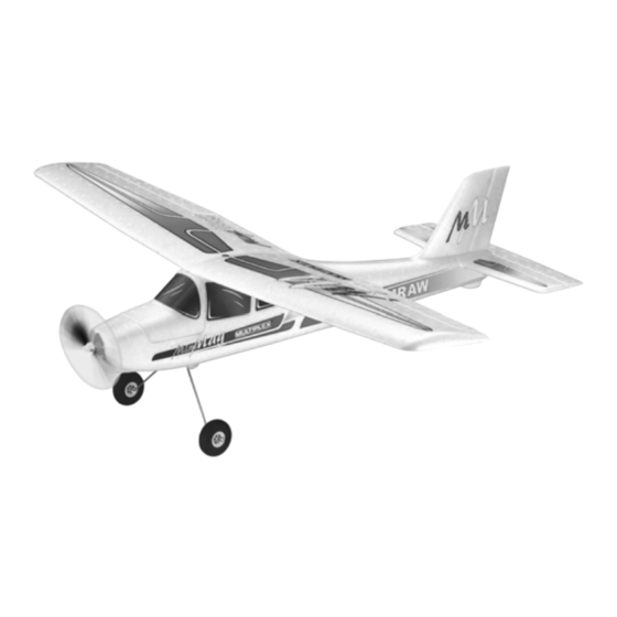
- Seite 4 Technische Daten: Spannweite 1010 mm Rumpflänge ü. a. 820 mm Fluggewicht ab 580 g Flächenbelastung (FAI) ab 26 g/dm² Antrieb ab Permax 400 6 V RC-Funktionen Höhen-, Seiten- und Motorsteuerung Option Querruder Wichtiger Hinweis Dieses Modell ist nicht aus Styropor ™! Daher sind Verklebungen mit Weißleim oder Epoxy nicht möglich. Verwenden Sie nur Cyanacrylatkleber, vorzugsweise in Verbindung mit Aktivator (Kicker).
- Seite 5 Servo einbauen Abb. 19 bzw 21, ggf. nacharbeiten. Motorhalter mit CA Stellen Sie das Servo mit der Fernsteuerung auf „Neutral“ Kleber flächig bestreichen und sorgfältig einkleben und montieren Sie die Servohebel so auf das Servo, dass Abb. 18. die Hebel in Neutralstellung 90° seitlich überstehen. Die Z-Biegung vom Seitenruderdraht in den Servohebel in das 12.
- Seite 6 dem Rumpf und H-Leitwerk positionieren und die Pass- 22. Querruderservokabel verlegen genauigkeit überprüfen. Achten Sie hier besonders dar- Das Servokabel in Richtung Tragflächenmitte verlegen. Das auf, dass das Seitenleitwerk 8 spaltfrei aufliegt und 90° Kabel nun geradlinig und hochkant stehend an der Vorder- zur Tragflächenauflage und Höhenleitwerk ist.
- Seite 7 Propeller montieren Die Servos und somit die Ruderausschläge werden mit Vor dem ersten Probelauf muß noch der Propeller mon- der richtigen Ausschlaggrösse angesteuert. Die Mitnahnme tiert werden. Je nach Antriebssatz kann dieses ggf. ab- von Seitenruder ins Querruder („Combi-Switch“) und die weichen.
- Seite 8 Motor wiederholt werden. Dabei darf sich die Reichweite nur unwesentlich verkürzen. Wir, das MULTIPLEX -Team, wünschen Ihnen beim Bauen und später beim Fliegen viel Freude und Erfolg. Falls etwas unklar ist, sollte auf keinen Fall ein Start er- folgen.
- Seite 9 Stückliste BK MiniMag # 21 4211 Lfd. Stück Bezeichnung Material Abmessungen Bauanleitung Papier DIN-A4 Dekorbogen bedruckte Klebefolie 400 x 700mm Rumpfhälfte links Elapor geschäumt Fertigteil Rumpfhälfte rechts Elapor geschäumt Fertigteil Kabinenhaube Elapor geschäumt Fertigteil Tragfläche Elapor geschäumt Fertigteil Höhenleitwerk Elapor geschäumt Fertigteil Seitenleitwerk Elapor geschäumt...
- Seite 10 Grundlagen am Beispiel eines Flugmodells Ein Flugzeug bzw. Flugmodell läßt sich mit den Rudern um folgende 3-Achsen steuern - Hochachse, Querachse und Längs- achse. Die Betätigung des Höhenruders ergibt eine Veränderung der Fluglage um die Querachse. Bei Seitenruderausschlag dreht das Modell um die Hochachse. Wird Querruder gesteuert, so rollt das Modell um die Längsachse. Da unser EasyStar V- Stellung im Tragflügel hat, kann hier auf Querruder verzichtet werden.
-
Seite 11: Auftriebskraft
Auftriebskraft α... - Seite 12 Familiarisez vous avec le kit d’assemblage! Le matériel utilisé pour la réalisation des pièces des kits MULTIPLEX est perpétuellement soumis à des contrôles pendant la phase de production. Nous espérons que vous êtes pleinement satisfait du contenu de ceux-ci. Néanmoins, nous vous demandons de bien vouloir vérifier chaque pièce (en fonction de la liste jointe) avant de vous lancer dans la...
- Seite 13 Données techniques: Envergure 1010 mm Longueur totale 820 mm Poids en vol à partir de 580 g Charge alaire (FAI) à partir de 26 g/dm² Propulsion à partir de Permax 400 6 V Fonctions RC Profondeur, direction et commande moteur, ailerons en option Information importante Ce modèle n’est pas en polystyrène™!De ce fait, un collage avec de la colle blanche ou époxy n’est pas possible.
- Seite 14 la tige de fixation dans les deux moitiés de fuselage, percez Unité de propulsion du Easy Glider E le stabilisateur de profondeur fig.11. Si vous optez pour (réducteur 3:1 avec Permax 400) # 33 2688 cette option, il faudra coupé la partie arrière du fuselage Avec l’entraînement Ø...
- Seite 15 15. Déblocage des gouvernes de profondeur et de ............direction En faisant bouger d’un côté puis de l’autre côté les Si vous souhaitez voler avec les ailerons (trois axes), gouvernes, vous les débloquez et les rendez plus souples poursuivez ici. –...
- Seite 16 Le moteur disponible dans le kit est déjà filtré en interne. Ce filtrage est suffisant si vous utilisez un régulateur MINI MAG système de radiocommande 3 canaux MULTIcont X-16 # 7 2271. Sans le MagicMixer #1 il faudrait utiliser au minimum une Dans le cas ou vous utilisez un autre régulateur, renforcez...
- Seite 17 Afin d’obtenir des caractéristiques de vol stables, vous vol régulier et droit du modèle. devez ajuster le centre de gravité de votre Mini Mag, comme tout autre modèle, afin que celui-ci se situe à un Familiarisez vous avec le modèle à une altitude suffisante, certain emplacement sur votre avion.
- Seite 18 Nous, le Team MULTIPLEX, vous souhaitons beaucoup de général MULTIPLEX. Les produits ont été testés par de plaisir et de succès pendant la construction et le pilotage. nombreux pilotes chevronnés et sont constamment améliorés pour eux.
- Seite 19 Nr. Nbr. Désignation Matière Dimensions Kit de propulsion 60-63 1 Support moteur Permax 400 (1pc) voir ci-dessous! 50 1 Moteur de propulsion Permax 400 6V Complet 52 1 Hélice Plastique 125 x 110mm Support moteur Permax 400 (1x) en 2 pièces avec vis 60 1 Face avant pour moteur Plastique injecté...
- Seite 20 Bases du pilotage d’un modèle réduit Un avion, comme un modèle réduit se pilote avec les gouvernes suivant 3 axes - l’axe vertiical, l’axe longitudinal et l’axe latéral. Une action sur la commande de profondeur conduit à une modification de la position de vol autour de l’axe latéral. Une action sur la gouverne de direction conduit à...
- Seite 21 Examine your kit carefully! MULTIPLEX model kits are subject to constant quality checks throughout the production process, and we sincerely hope that you are happy with the contents of your kit. However, we would ask you to check all the parts before you start construction, as we cannot exchange components which you have already worked on.
- Seite 22 Specification: output lever. Slip the inner tube 45 over the steel pushrod, Wingspan 1010 mm and slide both into the outer sleeve 43 from the servo end. Fuselage length overall 820 mm Fig. 05 All-up weight min. 580 g Wing loading (FAI) min. 26 g/dm²...
- Seite 23 Check that the parts fit together snugly, and carry out any Fit the canopy on the fuselage again, and check that it fits minor trimming required before reaching for the glue bottle. neatly. Fig. 23 Glue the wing bolt support assembly 33 / 34 in one fuselage shell.
- Seite 24 18. Installing the undercarriage smoothly, but without slop, then apply a tiny drop of cyano Fit the wheels 71 on the main undercarriage unit 70, using to the outside of the nuts on the point of a pin. Fit the two collets 72 to retain each one.
- Seite 25 2 x 40 Abb. 01 2 x 20 4 x 24 2 x 21 2 x 23 2 x 71 2 x 30 2 x 22 4 x 73 4 x 72 2 x 62 4 x 63 Abb. 02...
- Seite 26 Abb03 Abb. 04 glue glue Abb. 05 Abb. 06 Abb. 07 Abb. 08 Ø 26 Depron # 73 3199 Heckrad=Option. Die Teile liegen dem BK nicht bei! Abb.10 Tailwheel = option. Parts not Abb.09 included in the kit...
- Seite 27 Rest von Teil 44 PVC Rohr 2/3 mm Remainder of part 44; 2/3 mm Ø PVC tube Stahl/Steel Ø 1,3 mm Abb. 11 M 1:1 Stahl/Steel Ø 1,3 mm Das Teil liegt dem BK nicht bei! This part not included in the kit Abb.
- Seite 28 Abb. 15 Abb.16 MPX-Prop. 2 x 62 Abb. 17 Abb. 18 4 x 63 Mitnehmer für Ø 3,5 mm / 3.5 mm Ø driver # 33 2310 passende Luft- schraube / propeller 8 x 3,8“ # 73 3139 Abb. 19 Abb.
- Seite 29 Abb. 23 Abb.24 gängig machen! Abb. 26 Move to and fro to ease hinge Abb. 25 gängig machen! Abb. 27 Abb. 28 Move to and fro to ease hinge Abb.29 Abb.30...
- Seite 30 Abb. 32 Abb. 31 Abb. 34 Abb. 33 Abb. 36 Abb. 35 glue Abb. 38 Abb.37...
- Seite 31 Abb.40 Abb. 39 # 73 3069 Abb. 41 Abb. 42 Schwimmerbausatz/Float kit Abb.43...
- Seite 32 Ersatzteile (bitte bei Ihrem Fachhändler bestellen) Replacement parts (please order from your model shop) Pièces de rechanges (S.V.P. à ne commander que chez votre revendeur) Parti di ricambio (da ordinare presso il rivenditore) Repuestos (por favor, diríjase a su distribuidor) # 22 4177 # 22 4176 # 22 4175...
- Seite 33 - Servo travel adjustment - Optional combi-switch (coupled rudder / ailerons) Using this module the Mini Mag can be flown even with a transmitter such as the Ranger III, as supplied with the Note: when you apply a right-aileron command at the EasyStar and SpaceScooter RTF models.
- Seite 34 29. Balancing Don’t attempt tightly banked turns close to the ground at If your Mini Mag is to fly safely and stably it must balance first, and especially not on the landing approach. at the correct point - just like every other aircraft. Assemble...
- Seite 35 Parts List Mini Mag kit # 21 4211 Part No. off Description Material Dimensions Building instructions Paper Decal sheet Printed adhesive film 400 x 700 mm Left-hand fuselage shell Moulded Elapor foam Ready made Right-hand fuselage shell Moulded Elapor foam...
- Seite 36 Basic information relating to model aircraft Any aircraft, whether full-size or model, can be controlled around the three primary axes: vertical (yaw), lateral (pitch) and longitudinal (roll). When you operate the elevator, the model’s attitude alters around the lateral axis. If you apply a rudder command, the model swings around the vertical axis.
-
Seite 37: Auftriebskraft
Auftriebskraft α... - Seite 38 Prenda confidenza con il contenuto della scatola di montaggio! Le scatole di montaggio MULTIPLEX sono soggette, durante la produzione, ad un continuo controllo della qualità e siamo pertanto certi che Lei sarà soddisfatto con la scatola di montaggio. La preghiamo tuttavia, di controllare tutte le parti prima del loro utilizzo (consultando la lista materiale), poiché...
- Seite 39 Dati tecnici: foro dall’interno della squadretta del servo. Infilare quindi il Apertura alare 1010 mm tondino nella guaina 43, incollata in precedenza nella Lunghezza fusoliera sopra tutto 820 mm fusoliera. Fig. 05 Peso in ordine di volo da 580 g Carico alare (FAI) da 26 g/dm²...
- Seite 40 Incollare il gancio di chiusura capottina. Fig. 08 infine aprire attentamente. Spruzzare dell’attivatore sui punti d’incollaggio delle linguette. Fig. 22+23 7. Unire i semigusci fusoliera Per l’incollaggio usare colla ciano densa o di media 13. Fissare la squadretta sull’elevatore viscosità. Inserire il raccordo 25, verso l’esterno, nel foro più...
- Seite 41 18. Montare il carrello Con colla ciano, incollare le squadrette 24, con i fori rivolti Montare rispettivamente una ruota 71 con 2 collari 72 sul verso la ”cerniera”, nelle rispettive aperture. Spruzzare pri- carrello principiale 70. Fig. 33. Premere leggermente il ma sulle aperture l’attivatore.
- Seite 42 29. Bilanciare il modello modello attorno all’asse verticale. Il Suo Mini Mag, come ogni altro aereo, deve anche essere Con il MagicMixer #1 sono necessari almeno i seguenti bilanciato su un punto prestabilito, per ottenere delle doti canali: di volo stabili.
- Seite 43 Non decollare assolutamente se dovessero sorgere dei problemi. In questo caso fare controllare la radio (con Noi, il Suo team MULTIPLEX , Le auguriamo tanta batterie, interruttore, servi) dalla ditta produttrice. soddisfazione e successo nella costruzione e più tardi nel far volare questo straordinario modello.
- Seite 44 Lista materiale BK MiniMag # 21 4211 Pos.Pz. Descrizione Materiale Dimensioni Istruzioni di montaggio Carta DIN-A4 Decals Foglio adesivo stampato 400 x 700mm Semiguscio fusoliera sinistro Elapor espanso Finito Semiguscio fusoliera destro Elapor espanso Finito Capottina Elapor espanso Finito Elapor espanso Finito Piano di quota Elapor espanso...
- Seite 45 Nozioni fondamentali Come ogni aereo, anche gli aeromodelli, possono muoversi, grazie ai timoni, intorno ai seguenti 3 assi – d’imbardata, di beccheggio e di rollio. Il movimento dell’elevatore fa variare la direzione di volo attorno all’asse di beccheggio. Muovendo il direzionale, il modello gira sull’asse d’imbardata.
- Seite 46 Auftriebskraft α...
- Seite 47 ¡Familiarícese con el kit! Los kits de montaje de modelos MULTIPLEX siguen un estricto control de los materiales durante su fabricación. Esperamos que este kit de montaje sea de su agrado. Le rogamos, no obstante, que antes de trabajar con su modelo, se asegure de que todas las piezas (según la lista de componentes) están incluidas, ya que cualquier pieza que...
- Seite 48 Características técnicas: Envergadura 1010 mm Longitud (total) 820 mm Peso a partir de 580 g Carga alar desde (FAI) 26 g/dm² Motorización a partir de Permax 400 6 V Funciones RC T. de dirección y profundidad y control de motor. Opcional: Alerones Aviso importante ¡Este modelo no está...
- Seite 49 Coloque la funda de transmisión externa 44 en la parte Instale el motor 50 con la bancada 60+61. Si usa reductora, delantera del fuselaje como se le indica en la Img.06. recorte la bancada 61 a 25 mm Img. 20 Ponga por la parte plana la mitad del fuselaje sobre la mesa y pegue con cianocrilato la funda exterior de la 10.
- Seite 50 él depende que pueda aprovechar todas las cualidades largueros. El cable debe sobresalir unos 120 mm de la de vuelo del Mini Mag raíz de las alas, para que al instalar el receptor no se Img. 30 presente ningún tipo de problema.
- Seite 51 ¡Al usar este tipo de emisoras, no necesitará ni el sin capacidades de mezcla. Es suficiente para: MagicMixer #1 ni el cable en “V”! MINI MAG Emisoras de 3 canales La emisora debe tener: Sin el MagicMixer #1 será imprescindible de que disponga...
- Seite 52 Para conseguir un comportamiento noble durante el vuelo, el aterrizaje, no realizar „movimientos bruscos“ a poca su Mini Mag, al igual que cualquier otro avión, debe tener altura del suelo. Es preferible aterrizar de forma segura y su centro de gravedad en un punto determinado. Termine caminar unos pasos, a poner en peligro la integridad del de montar su modelo y coloque la batería.
- Seite 53 Lista de partes Kit MiniMag # 21 4211 Nº. Uds. Descripción Material Dimensiones Manual de instrucciones Papel DIN-A4 Lámina decorativa Lámina impresa 400 x 700mm Fuselaje (mitad izquierda) Elapor Pieza prefabricada Fuselaje (mitad derecha) Elapor Pieza prefabricada Cabina Elapor Pieza prefabricada Alas Elapor Pieza prefabricada...
- Seite 54 Principios básicos tomando como ejemplo un avión Un avión, o mejor dicho, un avión de radiocontrol, se manda con los timones por los siguientes 3 ejes: eje vertical, eje transversal y eje longitudinal. El accionamiento del timón de profundidad supone una modificación de la posición de vuelo en el eje transversal. En el caso de las desviaciones del timón de dirección, el modelo gira por el eje vertical.
- Seite 55 Auftriebskraft α...
- Seite 56 MULTIPLEX Modellsport GmbH & Co.KG Neuer Weg 2 D-75223 Niefern-Öschelbronn www.multiplex-rc.de...