Werbung
Quicklinks
FTR 101. ...
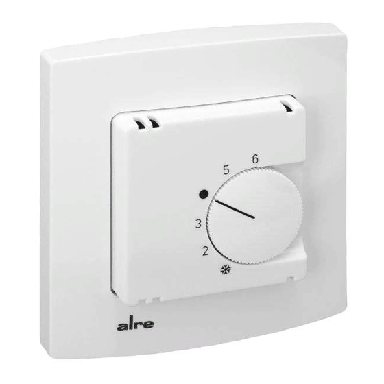
Elektromechanischer Raumtemperaturregler im Flächenschalterrahmen
Achtung!
Dieses Gerät darf nur durch einen Elektrofachmann geöffnet und gem. dem ent-
sprechenden Schaltbild in der Bedienungsanleitung installiert werden. Dabei
sind die bestehenden Sicherheitsvorschriften zu beachten.
1. Anwendung
Temperaturregelung in geschlossenen, trockenen Wohn- und Geschäftsräumen
bei üblichen Umgebungsbedingungen.
2. Funktion
Wird die eingestellte Temperatur unterschritten, schließt der Bimetallkontakt den
Heizkreis und es wird Wärme angefordert.
3. Einbaubedingungen
Zum Anschluss des Reglers ist kein Schutzleiter erforderlich, da das Gerät
schutzisoliert ist.
Tragring (6) mit Regler (7) immer auf Tapete montieren. BEI
MEHRFACHRAHMEN DEN REGLER AN DER UNTERSTEN STELLE POSI-
TIONIEREN. Ist als eigenständiges Gerät lieferbar oder mittels Zwischenrahmen
gemäß DIN 49075 in nahezu alle Flächenschaltersysteme adaptierbar.
Öffnen des Reglers
Knopf (1) mit Schraubendreher abhebeln; Schraube (2) lösen; Gehäusedeckel
(3) abziehen; (Zwischenrähmchen (4) - Bild 2) und Schalterrahmen (5) abneh-
men.
Gerät schließen
Gehäuse in umgekehrter Reihenfolge schließen.
Begrenzung des Einstellbereiches
Knopf (1) mit Schraubendreher abhebeln; Stift (8) abziehen; Anschlag rot (9) für
Maximaltemperatur und Anschlag blau (10) für Minimaltemperatur verdrehen;
Arretierungsstift (8) wieder einstecken. Knopf aufsetzen.
Bild 1
Montage des Reglers
ALRE - Standardversion
7
6
5
Begrenzung des Einstellbereichs
Limitation of the setting range
Flush framed electromechanical room controller
Figure 1
Installation of the controller
ALRE Standard-version
2
1
3
9
10
Caution!
D
A licensed electrician only is permitted to open this device and to install it accor-
ding to the circuit diagram in the casing lid / mounting instruction. The relevant
safety instructions have to be observed hereby.
1. Application!
This device has been specially designed for the control of temperatures in hou-
sing spaces and office rooms at usual ambient conditions.
2. Functioning
If the actual temperature falls below the adjusted temperature value, the bimetal
contact closes the heating circuit and heat supply is being requested.
3. Installation conditions
As the device is all insulated, no protective conductor is required to connect the
controller.
Install the controller (7) by fixing the support collar (6) on the wall surface.
WHEN USING MULTIPLE FRAMES, ALWAYS MAKE SURE TO MOUNT THE
CONTROLLER AT BOTTOM POSITION.
Can either be mounted as independent device or be mounted flush using DIN
49075 compliant intermediate frames which allow adaptation to almost all flush
switch frames currently available on the market.
How to open the controller housing
Remove knob (1) using a screw driver; loosen screw (2); remove the housing
cover (3) by pulling it off; remove both (the intermediate frame (4) - figure 2) and
the switch frame (5).
Closing the controller housing
Proceed in inverse order to close the controller housing again.
Limitation of the setting range
Remove knob (1) by levering it off using a screw driver; remove pin (8); turn red
stop (9) for maximum temperature and blue stop for minimum temperature; plug
the pin (8) in and put the knob on again.
Bild 2
Montage mit Zwischenrahmen
7
6
5
8
Figure 2
Installation with intermediate frame
2
3
4
1
GB
4 12 498 03
Werbung

Verwandte Anleitungen für Alre FTR 101.000


Inhaltszusammenfassung für Alre FTR 101.000
- Seite 1 (8) in and put the knob on again. Bild 1 Figure 1 Bild 2 Figure 2 Montage des Reglers Installation of the controller Montage mit Zwischenrahmen Installation with intermediate frame ALRE - Standardversion ALRE Standard-version Begrenzung des Einstellbereichs Limitation of the setting range 4 12 498 03...
- Seite 2 5. Maßzeichnung und Anschluss-Schaltbilder 5. Dimensional drawing and connection schemes Technische Änderungen vorbehalten - Subject to technical changes ALRE-IT Regeltechnik GmbH - Richard-Tauber-Damm 10 - D-12277 Berlin - Tel.: +49 (0)30 39984-0 - Fax: +49 (0)30 3917005 mail@alre.de - www.alre.de...