Inhaltsverzeichnis
Werbung
Verfügbare Sprachen
Verfügbare Sprachen
Quick Start
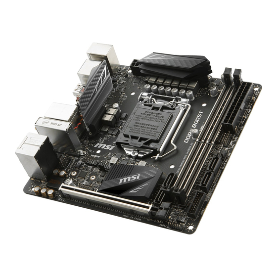
Thank you for purchasing the MSI
®
Z370I GAMING PRO CARBON
AC
motherboard. This Quick Start section provides demonstration
diagrams about how to install your computer. Some of the
installations also provide video demonstrations. Please link to the
URL to watch it with the web browser on your phone or tablet. You
may have even link to the URL by scanning the QR code.
Kurzanleitung
®
Danke, dass Sie das MSI
Z370I GAMING PRO CARBON AC
Motherboard gewählt haben. Dieser Abschnitt der Kurzanleitung
bietet eine Demo zur Installation Ihres Computers. Manche
Installationen bieten auch die Videodemonstrationen. Klicken Sie
auf die URL, um diese Videoanleitung mit Ihrem Browser auf Ihrem
Handy oder Table anzusehen. Oder scannen Sie auch den QR Code
mit Ihrem Handy, um die URL zu öffnen.
Présentation rapide
Merci d avoir choisi la carte mère MSI
®
Z370I GAMING PRO CARBON
AC. Ce manuel fournit une rapide présentation avec des illustrations
explicatives qui vous aideront à assembler votre ordinateur. Des
tutoriels vidéo sont disponibles pour certaines étapes. Cliquez sur
le lien fourni pour regarder la vidéo sur votre téléphone ou votre
tablette. Vous pouvez également accéder au lien en scannant le QR
code qui lui est associé.
MSI
®
Z370I
GAMING PRO CARBON
AC.
,
.
.
,
-
.
,
QR-
.
I
Quick Start
Werbung
Kapitel
Inhaltsverzeichnis

Verwandte Anleitungen für MSI Z370I GAMING PRO CARBON AC


Inhaltszusammenfassung für MSI Z370I GAMING PRO CARBON AC
- Seite 1 Handy oder Table anzusehen. Oder scannen Sie auch den QR Code mit Ihrem Handy, um die URL zu öffnen. Présentation rapide Merci d avoir choisi la carte mère MSI ® Z370I GAMING PRO CARBON AC. Ce manuel fournit une rapide présentation avec des illustrations explicatives qui vous aideront à...
- Seite 2 Installing a Processor/ Installation des Prozessors/ Installer un processeur/ http://youtu.be/bf5La099urI Quick Start...
- Seite 3 Installing DDR4 memory/ Installation des DDR4-Speichers/ Installer une mémoire DDR4/ DDR4 http://youtu.be/T03aDrJPyQs Quick Start...
- Seite 4 Connecting the Front Panel Header/ Anschließen der Frontpanel-Stiftleiste/ Connecter un connecteur du panneau avant/ http://youtu.be/DPELIdVNZUI HDD LED + Power LED + HDD LED - Power LED - Reset Switch Power Switch Reset Switch Power Switch JFP1 Reserved No Pin JFP1 HDD LED - HDD LED HDD LED +...
- Seite 5 Installing the Motherboard/ Installation des Motherboards/ Installer la carte mère/ Quick Start...
- Seite 6 Installing SATA Drives/ Installation der SATA-Laufwerke/ Installer le disque dur SATA/ SATA http://youtu.be/RZsMpqxythc Quick Start...
- Seite 7 Installing a Graphics Card/ Einbau der Grafikkarte/ Installer une carte graphique/ http://youtu.be/mG0GZpr9w_A Quick Start...
- Seite 8 Connecting Peripheral Devices/ Peripheriegeräte/ Connecter un périphérique anschliessen/ VIII Quick Start...
- Seite 9 Connecting the Power Connectors/ Stromanschlüsse anschliessen/ Connecter les câbles du module d alimentation/ http://youtu.be/gkDYyR_83I4 ATX_PWR1 CPU_PWR1 Quick Start...
-
Seite 10: Power On/ Einschalten/ Mettre Sous-Tension
Power On/ Einschalten/ Mettre sous-tension/ Quick Start... -
Seite 11: Inhaltsverzeichnis
Contents Safety Information ....................2 Specifications ......................3 Rear I/O Panel ....................... 8 LAN Port LED Status Table..................8 Audio Ports Configuration ..................8 Realtek HD Audio Manager ..................9 Overview of Components ..................11 M2_1: M.2 Slot (Key M) ..................12 CPU Socket ...................... -
Seite 12: Safety Information
Safety Information y The components included in this package are prone to damage from electrostatic discharge (ESD). Please adhere to the following instructions to ensure successful computer assembly. y Ensure that all components are securely connected. Loose connections may cause the computer to not recognize a component or fail to start. -
Seite 13: Specifications
Supports non-ECC, un-buffered memory y Supports Intel ® Extreme Memory Profile (XMP) * Please refer www.msi.com for more information on compatible memory. y 1x PCIe 3.0 x16 slot Expansion Slots y 1x HDMI™ port, supports a maximum resolution of... - Seite 14 Continued from previous page Intel ® Dual Band Wireless-AC 8265 module y The Wireless module is pre-install in the M2_2 (M.2 Key E) slot. Wireless LAN & y Supports Wi-Fi 802.11 a/b/g/n/ac, dual band (2.4GHz, ® Bluetooth 5GHz) up to 867 Mbps speed. y Supports Dual Mode Bluetooth ®...
- Seite 15 Continued from previous page y 1x 24-pin ATX main power connector y 1x 8-pin ATX 12V power connector y 4x SATA 6Gb/s connectors y 1x USB 3.1 Gen1 connector (supports additional 2 USB 3.1 Gen1 ports) y 1x USB 2.0 connector (supports additional 2 USB 2.0 ports) y 1x 4-pin CPU fan connector y 1x 4-pin system fan connector Internal Connectors...
- Seite 16 Continued from previous page y Drivers y APP MANAGER y SUPER CHARGER y COMMAND CENTER y LIVE UPDATE 6 y MSI SMART TOOL y RAMDISK y DPC LATENCY TUNER y FAST BOOT y X-BOOST y DRAGON EYE y GAMING APP...
- Seite 17 Continued from previous page y Storage ƒ Turbo M.2 y Fan ƒ Smart Fan Control y LED ƒ Mystic Light ƒ Mystic Light Extension (RGB) ƒ Corsair Extension ƒ Mystic light SYNC ƒ EZ DEBUG LED y Protection ƒ DDR4 Steel Armor ƒ...
-
Seite 18: Rear I/O Panel
Rear I/O Panel Wi-Fi Antenna connectors Audio Ports PS/2 USB 3.1 Gen2 DisplayPort Clear CMOS button USB 3.1 Gen1 USB 2.0 USB 3.1 Gen2 Optical S/PDIF-Out Type-C y Clear CMOS button - Power off your computer. Press and hold the Clear CMOS button for about 5-10 seconds to reset BIOS to default values. -
Seite 19: Realtek Hd Audio Manager
Realtek HD Audio Manager After installing the Realtek HD Audio driver, the Realtek HD Audio Manager icon will appear in the system tray. Double click on the icon to launch. Device Selection Advanced Settings Jack Status Application Enhancement Connector Main Volume Settings Profiles y Device Selection - allows you to select a audio output source to change the related... - Seite 20 Audio jacks to headphone and microphone diagram Audio jacks to stereo speakers diagram AUDIO INPUT Audio jacks to 7.1-channel speakers diagram AUDIO INPUT Rear Front Side Center/ Subwoofer Rear I/O Panel...
-
Seite 21: Overview Of Components
Overview of Components Top View DIMMA1 JUSB1 CPU Socket DIMMB1 SATA1 CPU_PWR1 ATX_PWR1 JCORSAIR1 JCI1 JRGB1 JFP1 JFP2 JBAT1 SYS_FAN1 SATA4 M2_2 SATA3 JAUD1 JUSB2 SATA2 JTPM1 PCI_E1 CPU_FAN1 Bottom View M2_1 Overview of Components... -
Seite 22: M2_1: M.2 Slot (Key M)
M2_1: M.2 Slot (Key M) Important Before you install the motherboard into the case, make sure your M.2 module has been installed properly. Intel ® RST only supports PCIe M.2 SSD with UEFI ROM. Intel ® Optane™ Memory Ready for all M.2 slot. Video Demonstration Watch the video to learn how to use M.2 Shield. -
Seite 23: Cpu Socket
Always unplug the power cord from the power outlet before installing or removing the CPU. Please retain the CPU protective cap after installing the processor. MSI will deal with Return Merchandise Authorization (RMA) requests if only the motherboard comes with the protective cap on the CPU socket. -
Seite 24: Dimm Slots
DIMM Slots DIMMA1 DIMMB1 Channel A Channel B Important Always insert memory modules in the DIMMA1 slot first. Due to chipset resource usage, the available capacity of memory will be a little less than the amount of installed. Based on Intel CPU specification, the Memory DIMM voltage below 1.35V is suggested to protect the CPU. -
Seite 25: Pci_E1: Pcie Expansion Slot
PCI_E1: PCIe Expansion Slot Important If you install a large and heavy graphics card, you need to use a tool such as MSI Gaming Series Graphics Card Bolster to support its weight to prevent deformation of the slot. When adding or removing expansion cards, always turn off the power supply and unplug the power supply power cable from the power outlet. -
Seite 26: Cpu_Pwr1, Atx_Pwr1: Power Connectors
CPU_PWR1, ATX_PWR1: Power Connectors These connectors allow you to connect an ATX power supply. CPU_PWR1 Ground +12V Ground +12V Ground +12V Ground +12V +3.3V +3.3V +3.3V -12V Ground Ground PS-ON# Ground Ground Ground ATX_PWR1 Ground Ground PWR OK 5VSB +12V +12V +3.3V Ground... -
Seite 27: Jusb1: Usb 2.0 Connector
JUSB1: USB 2.0 Connector This connector allows you to connect USB 2.0 ports on the front panel. USB0- USB1- USB0+ USB1+ Ground Ground No Pin Important Note that the VCC and Ground pins must be connected correctly to avoid possible damage. -
Seite 28: Cpu_Fan1, Sys_Fan1: Fan Connectors
CPU_FAN1, SYS_FAN1: Fan Connectors Fan connectors can be classified as PWM (Pulse Width Modulation) Mode or DC Mode. PWM Mode fan connectors provide constant 12V output and adjust fan speed with speed control signal. DC Mode fan connectors control fan speed by changing voltage. When you plug a 3-pin (Non-PWM) fan to a fan connector in PWM mode, the fan speed will always maintain at 100%, which might create a lot of noise. -
Seite 29: Jaud1: Front Audio Connector
JAUD1: Front Audio Connector This connector allows you to connect audio jacks on the front panel. MIC L Ground MIC R Head Phone R MIC Detection SENSE_SEND No Pin Head Phone L Head Phone Detection JCI1: Chassis Intrusion Connector This connector allows you to connect the chassis intrusion switch cable. Normal Trigger the chassis intrusion event... -
Seite 30: Jtpm1: Tpm Module Connector
JTPM1: TPM Module Connector This connector is for TPM (Trusted Platform Module). Please refer to the TPM security platform manual for more details and usages. LPC Clock 3V Standby power LPC Reset 3.3V Power LPC address & data pin0 Serial IRQ LPC address &... -
Seite 31: Jrgb1, Jcorsair1: Rgb Led Connectors
The JRGB1 connector allows you to connect the 5050 RGB LED strips 12V. The JCORSAIR1 connector can be used to connect the CORSAIR Individually Addressable RGB LED strips 5V or CORSAIR RGB LED fans, and control the RGB effects with MSI s software. -
Seite 32: Onboard Leds
Onboard LEDs EZ Debug LEDs These LEDs indicate the debug status of the motherboard. CPU - indicates CPU is not detected or fail. DRAM - indicates DRAM is not detected or fail. VGA - indicates GPU is not detected or fail. BOOT - indicates the booting device is not detected or fail. -
Seite 33: Bios Setup
Press Delete key, when the Press DEL key to enter Setup Menu, F11 to enter Boot Menu message appears on the screen during the boot process. y Use MSI FAST BOOT application. Click on GO2BIOS button and choose OK. The system will reboot and enter BIOS setup directly. -
Seite 34: Resetting Bios
Updating BIOS Updating BIOS with M-FLASH Before updating: Please download the latest BIOS file that matches your motherboard model from MSI website. And then save the BIOS file into the USB flash drive. Updating BIOS: 1. Insert the USB flash drive that contains the update file into the computer. -
Seite 35: Ez Mode
EZ Mode At EZ mode, it provides the basic system information and allows you to configure the basic setting. To configure the advanced BIOS settings, please enter the Advanced Mode by pressing the Setup Mode switch or F7 function key. XMP switch Setup Mode switch Screenshot... - Seite 36 y Information display - click on the CPU, Memory, Storage, Fan Info and Help buttons on left side to display related information. y Function buttons - enable or disable the LAN Option ROM, M.2/Optane Genie, HD audio controller, AHCI, RAID, CPU Fan Fail Warning Control and BIOS Log Review by clicking on their respective button.
-
Seite 37: Advanced Mode
Advanced Mode Press Setup Mode switch or F7 function key can switch between EZ Mode and Advanced Mode in BIOS setup. XMP switch Setup Mode switch Screenshot Search Language System information GAME BOOST switch Boot device priority bar BIOS menu BIOS menu selection selection... -
Seite 38: Oc Menu
OC Menu This menu is for advanced users who want to overclock the motherboard. Important Overclocking your PC manually is only recommended for advanced users. Overclocking is not guaranteed, and if done improperly, it could void your warranty or severely damage your hardware. If you are unfamiliar with overclocking, we advise you to use GAME BOOST function for easy overclocking. - Seite 39 fEIST [Enabled]* ® Enables or disables the Enhanced Intel SpeedStep Technology. [Enabled] Enables the EIST to adjust CPU voltage and core frequency dynamically. It can decrease average power consumption and average heat production. [Disabled] Disables EIST. fIntel Turbo Boost [Enabled]* Enables or disables the Intel ®...
- Seite 40 f Advanced DRAM Configuration Press Enter to enter the sub-menu. User can set the memory timing for each/ all memory channel. The system may become unstable or unbootable after changing memory timing. If it occurs, please clear the CMOS data and restore the default settings.
- Seite 41 f PCH Voltages control [Auto] These options allow you to set the voltages related to PCH. If set to Auto, BIOS will set these voltages automatically or you can set it manually. f CPU Specifications Press Enter to enter the sub-menu. This sub-menu displays the information of installed CPU.
- Seite 42 fIntel VT-D Tech [Disabled] Enables or disables Intel VT-D (Intel Virtualization for Directed I/O) technology. fHardware Prefetcher [Enabled] Enables or disables the hardware prefetcher (MLC Streamer prefetcher). [Enabled] Allows the hardware prefetcher to automatically pre-fetch data and instructions into L2 cache from memory for tuning the CPU performance.
- Seite 43 fEIST [Enabled] ® Enables or disables the Enhanced Intel SpeedStep Technology. This item will appear when OC Explore Mode is set to Normal. [Enabled] Enables the EIST to adjust CPU voltage and core frequency dynamically. It can decrease average power consumption and average heat production.
-
Seite 44: Software Description
Software Description Please download and update the latest utilities and drivers at www.msi.com Installing Windows ® 1. Power on the computer. 2. Insert the Windows ® 10 disc into your optical drive. 3. Press the Restart button on the computer case. - Seite 45 Inhalt Sicherheitshinweis ....................2 Spezifikationen ...................... 3 Rückseite E/A ......................8 LAN Port LED Zustandstabelle ................8 Konfiguration der Audioanschlüsse ............... 8 Realtek HD Audio Manager ..................9 Übersicht der Komponenten ................11 M2_1: M.2 Steckplatz (Key M) ................12 CPU Sockel ......................
-
Seite 46: Sicherheitshinweis
Sicherheitshinweis y Die im Paket enthaltene Komponenten sind der Beschädigung durch elektrostatischen Entladung (ESD). Beachten Sie bitte die folgenden Hinweise, um die erfolgreichen Computermontage sicherzustellen. y Stellen Sie sicher, dass alle Komponenten fest angeschlossen sind. Lockere Steckverbindungen können Probleme verursachen, zum Beispiel: Der Computer erkennt eine Komponente nicht oder startet nicht. -
Seite 47: Spezifikationen
Unterstützt den Dual-Kanal-Modus y Unterstützt non-ECC, ungepufferte Speicher y Unterstützt Intel ® Extreme Memory Profile (XMP) * Weitere Informationen zu kompatiblen Speicher finden Sie unter: http://www.msi.com. Erweiterung- y 1x PCIe 3.0 x16-Steckplatz anschlüsse y 1x HDMI ™ Anschluss, Unterstützung einer maximalen Auflösung von 4096x2160@30Hz, 2560x1600@60Hz... - Seite 48 Fortsetzung der vorherigen Seite Intel ® Dualband Wireless-AC 8265 Modul y Das Wireless-Modul ist im M2_2 (M.2 Key E) Steckplatz vorinstalliert. Wireless LAN & y Unterstützt Wi-Fi 802.11 a/b/g/n/ac, Dualband (2,4 GHz, 5 ® Bluetooth GHz) mit Datenraten von bis zu 867 Mbps. y Unterstützt einen Dual-Modus Bluetooth ®...
- Seite 49 Fortsetzung der vorherigen Seite y 1x 24-poliger ATX Stromanschluss y 1x 8-poliger ATX 12V Stromanschluss y 4x SATA 6Gb/s Anschlüsse y 1x USB 3.1 Gen1 Anschluss (unterstützt zusätzliche 2 USB 3.1 Gen1-Ports) y 1x USB 2.0 Anschluss (unterstützt zusätzliche 2 USB 2.0-Ports) y 1x 4-poliger CPU-Lüfter-Anschluss y 1x 4-poliger System-Lüfter-Anschluss...
- Seite 50 ™ , Google Toolbar, Google Drive y Norton ™ Internet Security Solution * Dieses Angebot steht nur für begrenzte Zeit zur Verfügung, weitere Informationen finden Sie unter www.msi.com y Audio ƒ Audio Boost 4 ƒ Nahimic 2 Besondere Funktionen y Netzwerk ƒ...
- Seite 51 Fortsetzung der vorherigen Seite y Speicherung ƒ Turbo M.2 y Lüfter ƒ Smart-Lüftersteuerung y LED ƒ Mystic Light ƒ Mystic Light Extension (RGB) ƒ Corsair Extension ƒ Mystic Light SYNC ƒ EZ DEBUG LED y Schutz ƒ DDR4 Steel Armor ƒ...
-
Seite 52: Rückseite E/A
Rückseite E/A Wi-Fi Antennen- anschlüsse Audioanschlüsse PS/2 USB 3.1 Gen2 DisplayPort Clear CMOS Taste USB 3.1 Gen1 USB 2.0 USB 3.1 Gen2 Optischer S/PDIF- Typ-C Ausgang y Clear CMOS Taste - Schalten Sie den Computer aus. Halten Sie die Taste „Clear CMOS für 5-10 Sekunden gedrückt, um das BIOS auf die Standardwerte zurückzusetzen. -
Seite 53: Realtek Hd Audio Manager
Realtek HD Audio Manager Nach der Installation des Realtek HD Audio-Treibers, wird das Symbol Realtek HD Audio Manager in der Taskleiste angezeigt. Klicken Sie doppelt auf dieses Symbol, um das Programm zu starten. Geräteauswahl Erweiterte Einstellungen Verbindungs- status Optimierungen Lautstärke Anschlüsse Profil y Geräteauswahl - Ermöglicht die Auswahl der Audio-Ausgangs Quelle. - Seite 54 Audiobuchsen für den Anschluss von einem Kopfhörer und Mikrofon Audiobuchsen für Stereo-Lautsprecher AUDIO INPUT Audiobuchsen für 7,1 Kanal Anlage AUDIO INPUT Rear Front Side Center/ Subwoofer Rückseite E/A...
-
Seite 55: Übersicht Der Komponenten
Übersicht der Komponenten Draufsicht DIMMA1 JUSB1 CPU Sockel DIMMB1 SATA1 CPU_PWR1 ATX_PWR1 JCORSAIR1 JCI1 JRGB1 JFP1 JFP2 JBAT1 SYS_FAN1 SATA4 M2_2 SATA3 JAUD1 JUSB2 SATA2 JTPM1 PCI_E1 CPU_FAN1 Unteransicht M2_1 Übersicht der Komponenten... -
Seite 56: M2_1: M.2 Steckplatz (Key M)
M2_1: M.2 Steckplatz (Key M) Wichtig Bevor Sie das motherboard in das Gehäuse einbauen, vergewissern Sie sich, dass das M.2-Modul korrekt installiert ist. Intel ® RST unterstützt nur PCIe M.2 SSD mit UEFI ROM. ® ™ Intel Optane Technik unterstützt alle M.2 Steckplätze. Video-Demonstration In diesem Video erfahren Sie, wie Sie die M.2-Abdeckung verwenden. -
Seite 57: Cpu Sockel
Sie jedoch bitte sicher, dass die betroffenen Komponenten mit den abweichenden Einstellungen während des Übertaktens zurecht kommen. Von jedem Versuch des Betriebes außerhalb der Produktspezifikationen kann nur abgeraten werden. MSI übernehmt keinerlei Garantie für die Schäden und Risiken, die aus einem unzulässigem Betrieb oder einem Betrieb außerhalb der Produktspezifikation resultieren. -
Seite 58: Dimm-Steckplätze
DIMM-Steckplätze DIMMA1 DIMMB1 Kanal A Kanal B Wichtig Um einen sicheren Systemstart zu gewährleisten, bestücken Sie immer DIMMA1 zuerst. Aufgrund der Chipsatzressourcennutzung wird die verfügbare Kapazität des Speichers kleiner sein als die Größe der installierten Speicherkapazität. Basierend auf der Intel CPU Spezifikation wird eine Speicherspannung unter 1,35 Volt vorgeschlagen, um die CPU zu schützen. -
Seite 59: Pci_E1: Pcie Erweiterungssteckplatz
PCI_E1: PCIe Erweiterungssteckplatz Wichtig Wenn Sie eine große und schwere Grafikkarte einbauen, benötigen Sie einen Grafikkarten-Stabilisator (Graphics Card Bolster) der das Gewicht trägt und eine Verformung des Steckplatzes vermeidet. Achten Sie darauf, dass Sie den Strom abschalten und das Netzkabel aus der Steckdose herausziehen, bevor Sie eine Erweiterungskarte installieren oder entfernen. -
Seite 60: Cpu_Pwr1, Atx_Pwr1: Stromanschlüsse
CPU_PWR1, ATX_PWR1: Stromanschlüsse Mit diesen Anschlüssen verbinden Sie die ATX Stromstecker. CPU_PWR1 Ground +12V Ground +12V Ground +12V Ground +12V +3.3V +3.3V +3.3V -12V Ground Ground PS-ON# Ground Ground Ground ATX_PWR1 Ground Ground PWR OK 5VSB +12V +12V +3.3V Ground Wichtig Stellen Sie sicher, dass alle Anschlüsse mit den richtigen Anschlüssen des Netzteils verbunden sind, um einen stabilen Betrieb der Hauptplatine sicherzustellen. -
Seite 61: Jusb1: Usb 2.0 Anschluss
(Erdung) bezeichneten Pins korrekt verbinden müssen, ansonsten kann es zu Schäden kommen. Um ein iPad, iPhone und einen iPod über USB-Anschlüsse aufzuladen, installieren ® Sie bitte die MSI SUPER CHARGER Software. JUSB2: USB 3.1 Gen1 Anschluss Mit diesem Anschluss können Sie die USB 3.1 Gen1 Anschlüsse auf dem Frontpanel verbinden. -
Seite 62: Cpu_Fan1, Sys_Fan1: Stromanschlüsse Für Lüfter
CPU_FAN1, SYS_FAN1: Stromanschlüsse für Lüfter Diese Anschlüsse können im PWM (Pulse Width Modulation) Modus oder Spannungsmodus betrieben werden. Im PWM-Modus bieten die Lüfteranschlüsse konstante 12V Ausgang und regeln die Lüftergeschwindigkeit per Drehzahlsteuersignal. Im DC-Modus bestimmen die Lüfteranschlüsse die Lüftergeschwindigkeit durch Ändern der Spannung. Wenn Sie ein 3-Pin (Non-PWM) Lüfter an einen PWM-Modus Lüfteranschluss anschließen, läuft der Lüfter mit höchster Drehzahl und kann unangenehm laut werden. -
Seite 63: Jaud1: Audioanschluss Des Frontpanels
JAUD1: Audioanschluss des Frontpanels Dieser Anschluss ermöglicht den Anschluss von Audiobuchsen eines Frontpanels. MIC L Ground MIC R Head Phone R MIC Detection SENSE_SEND No Pin Head Phone L Head Phone Detection JCI1: Gehäusekontaktanschluss Dieser Anschluss wird mit einem Kontaktschalter verbunden. Normal Löse den Gehäuseeingriff aus... -
Seite 64: Jtpm1: Tpm Anschluss
JTPM1: TPM Anschluss Dieser Anschluss wird für das TPM Modul (Trusted Platform Module) verwendet. Weitere Informationen über den Einsatz des optionalen TPM Modules entnehmen Sie bitte dem TPM Plattform Handbuch. LPC Clock 3V Standby power LPC Reset 3.3V Power LPC address & data pin0 Serial IRQ LPC address &... -
Seite 65: Jrgb1, Jcorsair1: Rgb Led Anschlüsse
Beachten Sie bitte, dass die Länge des LED-Streifens maximal 2 Meter betragen darf um eine Verdunkelung der LED zu verhindern. Schalten Sie die Stromversorgung aus und ziehen Sie das Netzkabel ab, bevor Sie die RGB-LED-Streifen ein- und ausbauen. Bitte verwenden Sie die MSI-Software zur Steuerung des LED-Leuchtstreifens. Übersicht der Komponenten... -
Seite 66: Onboard-Leds
Onboard-LEDs EZ Debug LEDs Diese LEDs zeigen den Debug-Status des Motherboards an. CPU - CPU wird nicht erkannt oder ist fehlerhaft. DRAM -DRAM wird nicht erkannt oder ist fehlerhaft. VGA - GPU wird nicht erkannt oder ist fehlerhaft. BOOT - Boot-Gerät wird nicht erkannt oder ist fehlerhaft. -
Seite 67: Bios-Setup
Während des BOOT-Vorgangs drücken Sie die Taste ENTF, wenn die Meldung Press DEL key to enter Setup Menu, F11 to enter Boot Menu erscheint. y Verwenden Sie die MSI FAST BOOT Anwendung. Klicken Sie die GO2BIOS-Taste und drücken Sie OK. Das System startet neu und geht direkt ins BIOS. -
Seite 68: Reset Des Bios
Aktualisierung des BIOS mit dem M-FLASH-Programm Vorbereitung: Laden Sie bitte die neueste BIOS Version, die dem Motherboard-Modell entspricht, von der offiziellen MSI Website herunter und speichern Sie die BIOS-Datei auf USB-Flash- Laufwerk. BIOS-Aktualisierungsschritte: 1. Schließen das USB-Flashlaufwerk mit der BIOS-Datei an den Computer. -
Seite 69: Ez Modus
EZ Modus Im EZ-Modus können Sie die Grundinformationen des Systems einsehen und grundlegende Einstellungen konfigurieren. Um sich die erweiterten BIOS- Einstellungen anzeigen zu lassen, aktivieren Sie bitte den Erweiterten Modus durch Drücken des Setup Modus Schalter oder der Funktionstaste F7. XMP Schalter Setup Modus Schalter Screenshot... - Seite 70 y Boot-Geräte Prioritätsleiste - Sie können die Gerätesymbole verschieben, um die Startreihenfolge zu ändern. Die Bootreihenfolge sind mit hoch (links) bis niedrig (rechts) bezeichnet. y Informationsanzeige - Klicken Sie auf die Schaltfläche CPU, Memory, Storage, Fan Info und Help auf der linken Seite, um die jeweiligen Informationen anzuzeigen. y Funktionstasten - Aktivieren oder deaktivieren Sie LAN Option ROM, M.2/Optane Genie, HD Audio Controller, AHCI, RAID, CPU Fan Fail Warning Control und BIOS Log Review durch Anklicken der zugehörigen Schaltfläche.
-
Seite 71: Erweiterter Modus
Erweiterter Modus Drücken Sie den Setup Modus Schalter oder die Funkionstaste F7, um zwischen dem EZ-Modus und Erweiterten-Modus im BIOS-Setup zu wechseln. XMP Schalter Setup Modus Schalter Screenshot Suchen Sprache System- information GAME BOOST Schalter Bootgeräte- Prioritätsleiste BIOS-Menü BIOS-Menü -Auswahl -Auswahl Menüanzeige y GAME BOOST Schalter/ XMP Schalter/ Setup Modus Schalter/ Screenshot/... -
Seite 72: Oc Menü
OC Menü In diesem Menü können Benutzer das BIOS anpassen und das Mainboard übertakten. Bitte führen Sie nur Änderungen durch, wenn Sie sich über das Ergebnis im Klaren sind. Sie sollten Erfahrung beim Übertakten haben, da Sie sonst das Motherboard oder Komponenten des Systems beschädigen können. - Seite 73 f CPU Ratio Offset When Running AVX [Auto] Legt einen Offset-Wert fest, um die Taktrate des CPU-Kerns zu reduzieren. Es könnte für die Wärmeableitung beim Betrieb des AVX-Instruction-Set hilfreich sein. Wenn die Einstellung auf [Auto] gesetzt ist, wird das BIOS diese Einstellungen automatisch konfigurieren.
- Seite 74 f Extreme Memory Profile (X.M.P.) [Disabled] Extreme Memory Profile (XMP) basieren auf Zertifizierungen für Speichermodule aus dem PC-Bereich. Aktivieren Sie die Funktion XMP oder wählen Sie ein Profil des Speichermoduls zum Übertakten aus. Diese Option steht zur Verfügung, wenn die installierten Speichermodule die XMP Technik unterstützen.
- Seite 75 fCPU Over Voltage Protection [Auto] Legen Sie die Spannungsgrenze für den CPU-Überspannungsschutz fest. Wenn die Einstellung auf Auto gesetzt ist, wird das BIOS diese Einstellungen automatisch konfigurieren. Höhere Spannung bietet weniger Sicherheit und kann das System beschädigen. fCPU Under Voltage Protection [Auto] Legen Sie die Spannungsgrenze für den CPU-Unterspannungsschutz fest.
- Seite 76 f CPU Specifications Drücken Sie die Eingabetaste <Enter>, um das Untermenü aufzurufen. Das Untermenü zeigt die Informationen der installierten CPU an. Zu diesen Informationen gelangen Sie, indem Sie die Taste [F4] drücken. Nur Anzeige. fCPU Technology Support Drücken Sie die Eingabetaste <Enter>, um das Untermenü aufzurufen. Das Untermenü...
- Seite 77 fIntel VT-D Tech [Disabled] Aktiviert oder deaktiviert die Intel VT-D (Intel Virtualization for Directed I/O) Technologie. fHardware Prefetcher [Enabled] Aktivieren oder deaktivieren Sie das Hardware Prefetcher (MLC Streamer prefetcher). [Enabled] Der CPU Hardware Prefetcher kann frühzeitig Daten und Anweisungen aus dem Speicher in den L2-Cache aden um die Cache-Latency Zeiten zu reduzieren.
- Seite 78 fPackage C State limit [Auto] Hier können Sie einen CPU C-State-Modus für Stromsparen auswählen, wenn das System im Leerlauf ist. Die Optionen des C-States ist abhängig von der installierten CPU. Diese Option wird angezeigt, wenn Intel C-State aktiviert ist. fCFG Lock [Enabled] Sperren oder Entsperren des MSR 0xE2[15]s, des CFG Lock-Bits.
-
Seite 79: Softwarebeschreibung
Softwarebeschreibung Laden Sie die neuesten Treiber und Dienstprogramme von www.msi.com herunter und aktualisieren Sie sie. ® Installation von Windows 1. Schalten Sie den Computer ein. ® 2. Legen Sie die Windows 10 Disk in das optisches Laufwerk. 3. Drücken Sie die Taste Restart auf dem Computergehäuse. - Seite 81 Table des matières Informations de sécurité ..................2 Spécifications ......................3 Panneau arrière Entrée/ Sortie ................8 Tableau explicatif de l état de la LED du port LAN ..........8 Configuration des ports audio ................8 Realtek HD Audio Manager ..................9 Vue d ensemble des composants ...............
-
Seite 82: Informations De Sécurité
Informations de sécurité y Les composants dans l emballage peuvent être endommagés par des décharges électrostatiques (ESD). Pour vous assurer de correctement monter votre ordinateur, veuillez vous référer aux instructions ci-dessous. y Assurez-vous de bien connecter tous les composants. En cas de mauvaise connexion, il se peut que l ordinateur ne reconnaisse pas le composant et que le démarrage échoue. -
Seite 83: Spécifications
Support non-ECC, mémoire un-buffered y Support Intel ® Extreme Memory Profile (XMP) * Veuillez vous référer au site www.msi.com pour plus d informations sur la mémoire compatible. y 1 x slot PCIe 3.0 x16 Slots d extension y 1 x port HDMI™, supportant une résolution maximum de 4096x2160@30Hz, 2560x1600@60Hz Sorties vidéo... - Seite 84 Suite du tableau de la page précédente Module Intel ® Dual Band Wireless-AC 8265 y Le module sans fil est préinstallé dans le slot M2_2 (M.2 Touche E). Wireless LAN et y Support Wi-Fi 802.11 a/b/g/n/ac, double bande (2.4GHz, ® Bluetooth 5GHz) jusqu à...
- Seite 85 Suite du tableau de la page précédente y 1 x connecteur d alimentation principal ATX 24 broches y 1 x connecteur d alimentation ATX 12V 8 broches y 4 x connecteurs SATA 6 Gb/s y 1 x connecteur USB 3.1 Gen1 (support de 2 autres ports USB 3.1 Gen1) y 1 x connecteur USB 2.0 (support de 2 autres ports USB 2.0) y 1 x connecteur de ventilateurs CPU 4 broches...
- Seite 86 Google Chrome™, Google Toolbar et Google Drive y Norton™ Internet Security Solution * Cette fonctionnalité dépend d une offre limitée dans le temps. Veuillez vous référer au site www.msi.com pour plus d informations. y Audio ƒ Audio Boost 4 ƒ...
- Seite 87 Suite du tableau de la page précédente y Stockage ƒ Turbo M.2 y Ventilateur ƒ Contrôle des ventilateurs y LED ƒ Mystic Light ƒ Mystic Light Extension (RGB) ƒ Corsair Extension ƒ Mystic light SYNC ƒ EZ DEBUG LED y Protection ƒ...
-
Seite 88: Panneau Arrière Entrée/ Sortie
Panneau arrière Entrée/ Sortie Connecteurs d antenne Wi-Fi Ports Audio PS/2 USB 3.1 Gen2 DisplayPort Bouton Clear CMOS USB 3.1 Gen1 USB 2.0 USB 3.1 Gen2 Sortie S/PDIF optique Type-C y Bouton Clear CMOS - Eteingnez votre ordinateur. Appuyez sur le bouton CMOS pendant environ 5-10 secondes pour remettre le BIOS aux valeurs par défaut. -
Seite 89: Realtek Hd Audio Manager
Realtek HD Audio Manager Après l installation du pilote Realtek HD Audio, l icône Realtek HD Audio Manager apparaît dans la barre des tâches du système. Double-cliquez sur l icône pour lancer le programme. Sélection du périphérique Paramètres avancés Etat des prises Jack Amélioration d application... - Seite 90 Ilustration de l utilisation des ports audio dédiés au casque et au microphone Ilustration de l utilisation du port audio dédié aux haut-parleurs AUDIO INPUT Ilustration de l utilisation des ports audio dédiés aux haut-parleurs 7.1 AUDIO INPUT Rear Front Side Center/ Subwoofer...
-
Seite 91: Vue D Ensemble Des Composants
Vue d ensemble des composants Vue de dessus Socket DIMMA1 JUSB1 processeur DIMMB1 SATA1 CPU_PWR1 ATX_PWR1 JCORSAIR1 JCI1 JRGB1 JFP1 JFP2 JBAT1 SYS_FAN1 SATA4 M2_2 SATA3 JAUD1 JUSB2 SATA2 JTPM1 PCI_E1 CPU_FAN1 Vue de dessous M2_1 Vue d ensemble des composants... -
Seite 92: M2_1: Slot M.2 (Touche M)
M2_1: Slot M.2 (Touche M) Important Avant d installer votre carte mère dans le boîtier PC, assurez-vous que le module M.2 est correctement inséré dans le slot. ® La technologie Intel RST supporte seulement un SSD M.2 PCIe avec une mémoire ROM UEFI. ®... -
Seite 93: Socket Processeur
électrique. Veuillez garder le capot de protection du processeur après l installation du processeur. Selon les exigences de RMA (Return Merchandise Authorization), MSI n acceptera pas les cartes mère dont le capot de protection aura été retiré. -
Seite 94: Slots Dimm
Slots DIMM DIMMA1 DIMMB1 Canal A Canal B Important Veillez à toujours insérer un module de mémoire dans l emplacement DIMMA1 en premier. Du fait des ressources utilisées par le chipset, la capacité de mémoire disponible est un peu moins élevée que celle installée. Basé... -
Seite 95: Pci_E1: Slot D Extension Pcie
Important Si vous installez une carte graphique lourde, il vous faut utiliser un outil comme la barre de support MSI Gaming Series pour supporter son poids et pour éviter la déformation du slot. Veillez à toujours mettre l ordinateur hors tension et à débrancher le cordon d alimentation avant d installer les cartes d extension. -
Seite 96: Cpu_Pwr1, Atx_Pwr1: Connecteurs D Alimentation
CPU_PWR1, ATX_PWR1: Connecteurs d alimentation Ces connecteurs vous permettent de relier une alimentation ATX. CPU_PWR1 Ground +12V Ground +12V Ground +12V Ground +12V +3.3V +3.3V +3.3V -12V Ground Ground PS-ON# Ground Ground Ground ATX_PWR1 Ground Ground PWR OK 5VSB +12V +12V +3.3V Ground... -
Seite 97: Jusb1: Connecteur Usb 2.0
Notez que les broches VCC et Terre doivent être branchées correctement afin d éviter tout dommage sur la carte mère. Pour recharger votre iPad, iPhone et iPod par l intermédiaire d un port USB, veuillez installer l utilitaire MSI ® SUPER CHARGER. -
Seite 98: Cpu_Fan1, Sys_Fan1: Connecteurs Pour Ventilateurs
CPU_FAN1, SYS_FAN1: Connecteurs pour ventilateurs Les connecteurs pour ventilateurs peuvent être utilisés en mode PWM (Pulse Width Modulation) et en mode DC. En mode PWM, les connecteurs fournissent une sortie de 12V constante et ajustent la vitesse des ventilateurs avec un signal de contrôle de vitesse. -
Seite 99: Jaud1: Connecteur Audio Avant
JAUD1: Connecteur audio avant Ce connecteur se lie aux jacks audio du panneau avant. MIC L Ground MIC R Head Phone R MIC Detection SENSE_SEND No Pin Head Phone L Head Phone Detection JCI1: Connecteur intrusion châssis Ce connecteur est relié à un câble d interrupteur intrusion châssis. Normal Commencer l activité... -
Seite 100: Jtpm1: Connecteur De Module Tpm
JTPM1: Connecteur de module TPM Ce connecteur est relié à un module TPM (Trusted Platform Module). Veuillez vous référer au manuel du module TPM pour plus d informations. LPC Clock 3V Standby power LPC Reset 3.3V Power LPC address & data pin0 Serial IRQ LPC address &... -
Seite 101: Jrgb1, Jcorsair1: Connecteurs Led Rgb
12V. Le connecteur JCORSAIR1 peut être utilisé pour connecter un ruban LED RGB adressables individuellement 5V ou un ventilateur LED RGB de marque Corsair. Vous pourrez contrôler les couleurs et les effets de lumière avec un logiciel MSI dédié. JRGB1... -
Seite 102: Indicateurs Led Embarqués
Indicateurs LED embarqués EZ Debug LEDs Ces LED indiquent l état de débogage de la carte mère. CPU - indique que le CPU n est pas détecté ou que son initialisation a échoué. DRAM - indique que la mémoire DRAM n est pas détectée ou que son initialisation a échoué. -
Seite 103: Configuration Du Bios
Menu, F11 to enter Boot Menu) sur l écran, veuillez appuyer sur la touche Suppr. y Quand l ordinateur est déjà en marche, vous pouvez utiliser l application MSI FAST BOOT. Cliquez sur le bouton GO2BIOS puis sur OK. Le système redémarre et entre dans l interface Setup du BIOS. -
Seite 104: Réinitialiser Le Bios
Avant la mise à jour : Veuillez télécharger la dernière version de BIOS compatible à votre carte mère sur le site MSI. Ensuite, veuillez sauvegarder le nouveau BIOS sur le lecteur flash USB. Mettre le BIOS à jour : 1. Connectez le lecteur Flash USB contenant le profil à l ordinateur. -
Seite 105: Ez Mode (Mode Simplifié)
EZ Mode (mode simplifié) Le mode EZ vous fournit les informations basiques du système et vous permet de configurer les réglages de base. Si vous souhaitez configurer les réglages du BIOS, veuillez utiliser le mode Advanced en appuyant sur le switch Setup Mode (Interrupteur de modes de réglages) ou la touche de fonction F7. - Seite 106 y Informations du système - montre la vitesse et la tension du processeur et de la mémoire, la température du processeur et de la carte mère, le type de carte mère et de processeur, la capacité mémoire, la version du BIOS et la date d installation. y Barre priorité...
-
Seite 107: Advanced Mode (Mode Avancé)
Advanced Mode (mode avancé) Appuyez sur le Setup Mode switch (interrupteur de modes de réglages) ou sur la touche de fonction F7 pour commuter entre le mode simplifié et le mode avancé. Interrupteur de Capture Interrupteur XMP Recherche modes de réglages d écran Langue Information... -
Seite 108: Oc Menu (Menu Overclocking)
OC Menu (menu overclocking) Ce menu est destiné aux utilisateurs avancés souhaitant overclocker leur carte mère. Important L overclocking manuel du PC n est recommandé que pour les utilisateurs avancés. L overclocking n est pas garanti et une mauvaise manipulation peut rendre nulle votre garantie et sévèrement endommager votre matériel. - Seite 109 f Adjusted Ring Frequency Montre la fréquence Ring modifiée. Fonctionne en lecture seule. f Misc Setting* Appuyez sur les touches Entrée et + ou - pour ouvrir ou fermer les 3 paramètres suivants, relatifs aux fonctionnalités du processeur. fEIST [Enabled]* Active ou désactive la technologie Enhanced Intel ®...
- Seite 110 f Adjusted DRAM Frequency Affiche la fréquence ajustée de la mémoire. Fonctionne en lecture seule. f Memory Try It ! [Disabled] Memory Try It! permet d améliorer la compatibilité ou les performances en optimisant les préréglages de la mémoire. f AIDA64 Memory Boost [Auto] Active ou désactive la fonction d amplification de la mémoire pour le benchmark de AIDA64.
- Seite 111 fCPU Over Current Protection [Auto] Définit une limite actuelle pour la protection contre la surcharge du CPU. En Auto, le BIOS configure automatiquement ce réglage. fCPU Switching Frequency [Auto] Définit la vitesse de fonction du PWM pour stabiliser la tension du coeur CPU et minimiser minimize la gamme d ondulation.
- Seite 112 f CPU Features Appuyez sur la touche Entrée pour accéder au sous-menu. fHyper-Threading [Enabled] La technologie d hyper-threading traite chaque cœur processeur comme un processeur logique indépendant doté de ses propres données et permet de les faire fonctionner de manière simultanée. Ainsi, les performances système sont grandement améliorées.
- Seite 113 fIntel Adaptive Thermal Monitor [Enabled] Active ou désactive la fonction de régulation adaptative de la température du moniteur Intel pour protéger le processeur contre la surchauffe. [Enabled] Ralentit l horloge du cœur processeur lorsque sa température dépasse la température du régulateur adaptatif. [Disabled] Désactive cette fonction.
- Seite 114 fLong Duration Power Limit (W) [Auto] Définit le niveau d alimentation maximum que le TDP (enveloppe thermique) du processeur peut supporter sur une longue période et en mode Turbo Boost. fLong Duration Maintained (s) [Auto] Définit la durée d utilisation de la fonction Long Duration Power Limit (W). fShort Duration Power Limit (W) [Auto] Définit le niveau d alimentation maximum que le TDP (enveloppe thermique) du processeur peut supporter sur une courte période et en mode Turbo Boost.
-
Seite 115: Informations Sur Les Logiciels
Informations sur les logiciels Veuillez vous référer au site www.msi.com pour télécharger et mettre à jour les derniers utilitaires et pilotes. ® Installer Windows 1. Allumez l ordinateur. ® 2. Insérez le disque de Windows 10 dans le lecteur optique. - Seite 117 ............2 ................ 3 ............8 LAN ........... 8 ................8 Realtek HD Audio ................9 ............... 11 M2_1: M.2 ( M) ................12 ..................13 DIMM ......................14 M2_2: M.2 Wi-Fi ( E) ............14 PCI_E1: PCIe ..............15 SATA1~4: SATA 6 / .................
- Seite 118 ƒ ƒ ƒ ƒ ƒ 60 C (140 F), .the motherboard.
- Seite 119 4500(OC)/ 4400(OC)/ 4333(OC)/ 4266(OC)/ 4133(OC)/ 4000(OC)/ 3866(OC)/ 3733(OC)/ 3600(OC)/ 3466(OC)/ 3400(OC)/ 3333(OC)/ 3300(OC)/ 3200(OC)/ 3000(OC)/ 2800(OC)/ 2667/ 2400/ 2133 non-ECC, Intel ® Extreme Memory Profile (XMP) www.msi.com y 1x PCIe 3.0 x16 y 1x ™ HDMI 4096x2160@30 , 2560x1600@60 y 1x...
- Seite 120 Intel ® Dual Band Wireless-AC 8265 M2_2 (M.2 ® Wi-Fi Bluetooth Wi-Fi 802.11 a/b/g/n/ac, (2.4 ® Dual Mode Bluetooth 2.1, 2.1+EDR, 3.0, 4.0, BLE, 4.2 ASMedia ® ASM3142 ƒ 1x USB 3.1 Gen2 (SuperSpeed USB 10Gbps) Type-C ƒ 1x USB 3.1 Gen2 (SuperSpeed USB 10Gbps) Type-A ®...
- Seite 121 y 1x 24- y 1x 8- ATX 12 y 4x SATA 6 y 1x USB 3.1 Gen1 ( USB 3.1 Gen1) y 1x USB 2.0 connector ( USB 2.0) y 1x 4- y 1x 4- Water Pump y 1x y 2x y 1x y 1x y 1x...
- Seite 122 APP MANAGER y SUPER CHARGER y COMMAND CENTER y LIVE UPDATE 6 y MSI SMART TOOL y RAMDISK y DPC LATENCY TUNER y FAST BOOT y X-BOOST y DRAGON EYE y GAMING APP y MYSTIC LIGHT y GAMING LAN MANAGER...
- Seite 123 ƒ Turbo M.2 ƒ ƒ Mystic Light ƒ Mystic Light Extension (RGB) ƒ Corsair Extension ƒ Mystic light SYNC ƒ EZ DEBUG LED ƒ DDR4 Steel Armor ƒ PCI-E Steel Armor ƒ DDR4 Boost ƒ Lightning USB ƒ USB Type A+C ƒ...
-
Seite 124: Lan
Wi-Fi PS/2 USB 3.1 Gen2 DisplayPort CMOS USB 3.1 Gen1 USB 2.0 USB 3.1 Gen2 S/PDIF-Out Type-C CMOS - CMOS 5-10 BIOS... -
Seite 125: Realtek Hd Audio
Realtek HD Audio Realtek HD Audio, Realtek HD Audio Manager. - Seite 126 AUDIO INPUT AUDIO INPUT Rear Front Side Center/ Subwoofer...
- Seite 127 DIMMA1 JUSB1 DIMMB1 SATA1 CPU_PWR1 ATX_PWR1 JCORSAIR1 JCI1 JRGB1 JFP1 JFP2 JBAT1 SYS_FAN1 SATA4 M2_2 SATA3 JAUD1 JUSB2 SATA2 JTPM1 PCI_E1 CPU_FAN1 M2_1...
-
Seite 128: M2_1: M.2 ( M)
M2_1: M.2 ( Intel ® PCIe M.2 SSD UEFI ROM. Intel ® Optane ™ M.2. M.2 Shield. https://youtu.be/NwtQBpkUazs... - Seite 129 LGA 1151 LGA 1151 , MSI « ». ®...
-
Seite 130: Dimm
DIMM DIMMA1 DIMMB1 DIMMA1. DIMM 1.35 . Windows, Windows. SPD (Serial Presence Detect). BIOS Memory Try It!, M2_2: M.2 Wi-Fi ( M.2 Wi-Fi. -
Seite 131: Pci_E1
PCI_E1: PCIe MSI Gaming Series Graphics Card Bolster SATA1~4: SATA 6 SATA 6 SATA. SATA4 SATA3 SATA1 SATA2 SATA SATA... -
Seite 132: Cpu_Pwr1, Atx_Pwr1
CPU_PWR1, ATX_PWR1: ATX. CPU_PWR1 Ground +12V Ground +12V Ground +12V Ground +12V +3.3V +3.3V +3.3V -12V Ground Ground PS-ON# Ground Ground Ground ATX_PWR1 Ground Ground PWR OK 5VSB +12V +12V +3.3V Ground JFP1, JFP2: JFP1 HDD LED + Power LED + HDD LED - Power LED - Reset Switch... -
Seite 133: Jusb1
JUSB1: USB 2.0 USB 2.0 USB0- USB1- USB0+ USB1+ Ground Ground No Pin iPad, iPhone iPod USB, ® SUPER CHARGER. JUSB2: USB 3.1 Gen1 USB 3.1 Gen1 Power USB2.0+ USB3_RX_DN USB2.0- USB3_RX_DP Ground Ground USB3_TX_C_DP USB3_TX_C_DN USB3_TX_C_DN USB3_TX_C_DP Ground Ground USB3_RX_DP USB2.0- USB3_RX_DN... -
Seite 134: Cpu_Fan1, Sys_Fan1
CPU_FAN1, SYS_FAN1: : PWM (PulseWidth Modulation) 12 , (Non-PWM) PWM, (PWM DC), CPU_FAN1 SYS_FAN1 BIOS > HARDWARE MONITOR : PWM PWM/ DC. Ground +12V Ground Voltage Control Sense Speed Control Signal Sense... -
Seite 135: Jaud1
JAUD1: MIC L Ground MIC R Head Phone R MIC Detection SENSE_SEND No Pin Head Phone L Head Phone Detection JCI1: JCI1. BIOS > SETTINGS > Security > Chassis Intrusion Configuration. Chassis Intrusion Enabled. F10, Enter, Yes. BIOS > SETTINGS > Security > Chassis Intrusion Configuration. Chassis Intrusion, Reset. -
Seite 136: Jtpm1: Tpm
JTPM1: (Trusted Platform Module). LPC Clock 3V Standby power LPC Reset 3.3V Power LPC address & data pin0 Serial IRQ LPC address & data pin1 5V Power LPC address & data pin2 No Pin LPC address & data pin3 Ground LPC Frame Ground JBAT1:... -
Seite 137: Jrgb1, Jcorsair1
JRGB1, JCORSAIR1: RGB LED JRGB1 5050 RGB 12 . JCORSAIR1 CORSAIR (5 ) CORSAIR MSI. JRGB1 JCORSAIR1 JRGB1 JCORSAIR1 Data +12V Ground 5050 RGB LED JRGB1 JRGB1 5050 RGB (12 /G/R/B) 3 (12 ). RGB, ®... -
Seite 138: Dimm
CPU - DRAM - DRAM VGA - BOOT - DIMM DIMM PCIe x16 PCIe x16. PCIe x8, x4, x1 PCI_E1... -
Seite 139: Bios
BIOS BIOS, BIOS BIOS BIOS, HELP. BIOS BIOS. Delete, Press DEL key to enter Setup Menu, F11 to enter Boot Menu MSI FAST BOOT. GO2BIOS BIOS. GO2BIOS Memory-Z F10: F12: FAT / FAT32 Ctrl+F: BIOS... -
Seite 140: Bios
Clear CMOS CMOS. BIOS, CMOS . BIOS BIOS M-FLASH BIOS MSI, BIOS USB. BIOS: USB, <Ctrl+F5>. BIOS BIOS. BIOS Live Update 6 BIOS: MSI LIVE UPDATE 6. BIOS Update. Scan. Download, BIOS. Next In Windows mode. Next Start BIOS. BIOS... - Seite 141 BIOS, GAME BOOST M-Flash GAME BOOST - GAME BOOST. GAME BOOST, XMP - X.M.P. (Extreme Memory Profile). X.M.P. X.M.P. F12, USB ( FAT/ FAT32). Ctrl + F BIOS. BIOS, F6, F10 F12. BIOS...
- Seite 142 BIOS BIOS CPU, Memory, Storage, Fan Info Help LAN Option ROM, M.2/Optane Genie, HD audio controller, AHCI, RAID, CPU Fan Fail Warning Control BIOS Log Review, y M-Flash - M-Flash. BIOS BIOS, BIOS. ƒ BIOS , OC..., . .) BIOS. ƒ...
- Seite 143 BIOS. GAME BOOST BIOS BIOS GAME BOOST/ XMP/ BIOS - ƒ SETTINGS - ƒ OC - ƒ M-FLASH - BIOS USB ƒ OC PROFILE - ƒ HARDWARE MONITOR - ƒ BOARD EXPLORER - BIOS BIOS...
- Seite 144 « » GAME BOOST. f OC Explore Mode [Normal] [Normal] BIOS. [Expert] BIOS Expert. f CPU Ratio [Auto] f Adjusted CPU Frequency f CPU Ratio Offset When Running AVX [Auto] AVX. Auto, BIOS BIOS...
- Seite 145 f Ring Ratio [Auto] f Adjusted Ring Frequency Ring. f Misc Setting* Enter, + fEIST [Enabled]* ® Enhanced Intel SpeedStep. [Enabled] EIST [Disabled] EIST. fIntel Turbo Boost [Enabled]* Intel ® Turbo Boost. [Enabled] [Disabled] fEnhanced Turbo [Auto]* Enhanced Turbo [Auto] BIOS.
- Seite 146 f DRAM Frequency [Auto] (DRAM). f Adjusted DRAM Frequency DRAM. f Memory Try It ! [Disabled] f AIDA64 Memory Boost [Auto] Memory Boost AIDA64. [Auto] BIOS [Enabled] AIDA64. [Disabled] f Advanced DRAM Configuration Enter CMOS CMOS/ CMOS BIOS, f DigitALL Power Enter fCPU Loadline Calibration Control [Auto] load-line calibration...
- Seite 147 fCPU Lite Load [Auto] Auto. fCPU Over Current Protection [Auto] Auto, BIOS fCPU Switching Frequency [Auto] MOSFET. MOSFET Auto, BIOS fCPU VRM Over Temperature Protection [Enabled] CPU VRM f CPU Voltages control [Auto] Auto, BIOS f DRAM Voltages control [Auto] Auto, BIOS f PCH Voltages control [Auto] Auto, BIOS...
- Seite 148 f MEMORY-Z Enter [F5]. fDIMMx Memory SPD Enter f CPU Features Enter fHyper-Threading [Enabled] Intel Hyper-Threading [Enable] Intel Hyper-Threading. [Disabled] fActive Processor Cores [All] fLimit CPUID Maximum [Disabled] CPUID. [Enabled] BIOS CPUID CPUID. [Disabled] CPUID. fIntel Virtualization Tech [Enabled] Intel Virtualization. [Enabled] Intel Virtualization [Disabled]...
- Seite 149 fHardware Prefetcher [Enabled] (MLC Streamer prefetcher). [Enabled] [Disabled] fAdjacent Cache Line Prefetch [Enabled] (MLC Spatial prefetcher). [Enabled] [Disabled] fCPU AES Instructions [Enabled] CPU AES (Advanced Encryption Standard-New Instructions). fIntel Adaptive Thermal Monitor [Enabled] [Enabled] [Disabled] fIntel C-State [Auto] Intel C-state. C-state - ACPI.
- Seite 150 fCFG Lock [Enabled] MSR 0xE2[15], CFG. [Enabled] CFG. [Disabled] CFG. fEIST [Enabled] ® Enhanced Intel SpeedStep. OC Explore Mode Normal. [Enabled] EIST [Disabled] EIST. fIntel Turbo Boost [Enabled] Intel ® Turbo Boost. Normal [Enabled] [Disabled] fLong Duration Power Limit (W) [Auto] Turbo Boost.
-
Seite 151: Windows 10
Windows ® Windows ® Restart POST (Power-On Self Test) Press any key to boot from CD or DVD... Windows ® Windows ® ® Driver Disc Install. ® Driver Disc Utilities. Install. -
Seite 153: Regulatory Notices
The point of contact for regulatory matters is MSI, recycling and disposing of their end-of-life products. MSI-NL Eindhoven 5706 5692 ER Son. y Visit the MSI website and locate a nearby distributor for further recycling information. y Users may also reach us at gpcontdev@msi.com for... - Seite 154 MSI will comply with the product take entregar a una empresa autorizada para la recogida de back requirements at the end of life of MSI-branded estos residuos.
- Seite 155 K t ngày 01/12/2012, t t c các s n ph m do công illetve környezetvédőként fellépve az MSI emlékezteti ty MSI s n xu t tuân th Thông t s 30/2011/TT-BCT Önt, hogy ... quy đ nh t m th i v gi i h n hàm l ng cho phép c a...
- Seite 156 Alternatively, please try the following help resources for further guidance. y Visit the MSI website for technical guide, BIOS updates, driver updates, and other information: http://www.msi.com y Register your product at: http://register.msi.com...