
Verwandte Anleitungen für HomeMatic IP HmIPW-STH


Inhaltszusammenfassung für HomeMatic IP HmIPW-STH
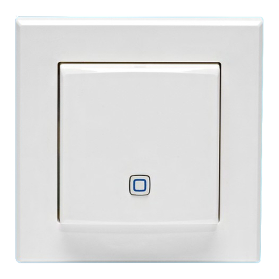
- Seite 1 Wired Temperatur- und Luftfeuchtigkeitssensor – innen Wired Temperature and Humidity Sensor – indoor HmIPW-STH | HmIPW-STH-A Installations- und Bedienungsanleitung Installation and operating manual...
- Seite 2 Installations- und Bedienungsanleitung Inhaltsverzeichnis Lieferumfang ....................3 Hinweise zur Anleitung ................3 Gefahrenhinweise ..................3 Funktion und Geräteübersicht ..............4 Allgemeine Systeminformationen .............5 Inbetriebnahme .....................5 Installationshinweise ..................5 Installation ......................6 Montage in Mehrfachkombinationen ............. 8 Anlernen ....................... 8 Fehlercodes und Blinkfolgen ..............10 Wiederherstellung der Werkseinstellungen Wartung und Reinigung ................
- Seite 3 Lieferumfang Lieferumfang Betreiben Sie das Gerät nur in trockener sowie staubfreier Um- Wired Temperatur- und gebung, setzen Sie es keinem Luftfeuchtigkeitssensor – innen Einfluss von Feuchtigkeit, Vibrati- 1x Wechselrahmen onen, ständiger Sonnen- oder 1x Montageplatte anderer Wärmeeinstrahlung, Kälte und keinen mechanischen Belas- 2x Schrauben 3,2 x 15 mm tungen aus.
- Seite 4 Das Gerät ist Teil der Gebäudeins- tallation. Bei der Planung und Geräteübersicht Errichtung sind die einschlägigen Mit dem Homematic IP Wired Tem- Normen und Richtlinien des Lan- peratur- und Luftfeuchtigkeitssensor des zu beachten. Das Gerät ist können Sie Ihre Fußbodenheizung in ausschließlich für den Betrieb am...
- Seite 5 Allgemeine Systeminformationen 5 Allgemeine Beachten Sie die auf dem Gerät angegebene Abisolierlänge der Systeminformationen anzuschließenden Leiter. Dieses Gerät ist Teil des Homematic IP Beachten Sie bei der Installation Smart-Home-Systems und kommuni- die Gefahrenhinweise gemäß (s. „2 ziert über das Homematic IP Protokoll. Hinweise zur Anleitung“...
- Seite 6 Inbetriebnahme Installation • Auswertung der Messergebnisse; • Auswahl des Elektro-Installations- Der Bus wird vom Homematic IP materials zur Sicherstellung der Wired Access Point Abschaltbedingungen; ( HmIPW-DRAP) gespeist. Weitere • IP-Schutzarten; Informationen dazu können Sie der Bedienungsanleitung des • Einbau des Elektroinstallationsma- Wired Access Points entnehmen.
- Seite 7 Inbetriebnahme • Schließen Sie den Homematic IP Wired Bus an die Busanschluss- klemmen (E) an. Zum Anschließen und Lösen der einzelnen Adern betätigen sie den orangen Betäti- gungsdrücker mit Hilfe eines klei- nen Schraubendrehers. Abbildung 5 • Setzen Sie den Rahmen Ihrer vor-...
- Seite 8 Inbetriebnahme • Stellen Sie die Spannungsversor- Die Rahmen folgender Hersteller kön- gung wieder her. nen verwendet werden: Hersteller Rahmen Berker S.1, B.1, B.3, B.7 Glas carat*, future linear*, solo*, Busch-axcent*, Busch-Jaeger Busch-dynasty*, balance SI ELSO System 55, Standard GIRA 55, E2, E22, Event, Abbildung 7 Esprit 1-M, Atelier-M, M-...
- Seite 9 Luftfeuchtigkeitssensors gehen Sie wie folgt vor: • Zur Bestätigung eines erfolgrei- chen Anlernvorgangs leuchtet die • Öffnen Sie die Homematic IP App LED grün. Das Gerät ist nun ein- auf Ihrem Smartphone. satzbereit. • Wählen Sie den Menüpunkt „Gerät •...
- Seite 10 Fehlercodes und Blinkfolgen Fehlercodes und Blinkfolgen Blinkcode Bedeutung Lösung Warten Sie, bis die Über- Kurzes oranges Blinken Datenübertragung tragung beendet ist. 1x langes grünes Leuch- Sie können mit der Bedie- Vorgang bestätigt nung fortfahren. 1x langes rotes Leuchten Vorgang fehlgeschlagen Versuchen Sie es erneut.
- Seite 11 Wartung und Reinigung 9 Wartung und Reinigung merksam, dass Sie als Endnutzer ei- genverantwortlich für die Löschung Das Gerät ist für Sie bis auf einen personenbezogener Daten auf dem zu eventuell erforderlichen Batterie- entsorgenden Elektro- und Elektronik- wechsel wartungsfrei. Überlassen Altgerät sind.
- Seite 12 Technische Daten 11 Technische Daten Geräte-Kurzbezeichnung: HmIPW-STH, HmIPW-STH-A Versorgungsspannung: 24 VDC, +5 % -20 %, SELV Stromaufnahme: 20 mA max. Leitungsart u. -querschnitt: Starre Leitung 0,12-0,50 mm² Installation: nur in Schalterdosen (Gerätedosen) gemäß DIN 49073-1 Schutzart: IP20 Schutzklasse: Umgebungstemperatur: 0 bis 50 °C...
- Seite 13 Installation and operating manual Table of contents Package contents..................14 Information about this manual ..............14 Hazard information ..................14 Function and device overview ..............15 General system information ..............16 Start-up ......................16 Installation instructions ................... 16 Installation ......................17 Installation in multiple combinations ............19 Pairing .........................
- Seite 14 Package contents Package contents Do not use the device if there are signs of damage to the housing, Wired Temperature and control elements or connecting Humidity Sensor – indoor sockets, for example. If you have 1x Clip-on frame any doubts, have the device che- 1x Mounting plate cked by an expert.
- Seite 15 Homematic IP Wired bus only. The Homematic IP Floor Heating Actuators Homematic IP Wired bus is a SELV and adapt heating phases to your indi- power circuit. Common cable vidual needs. routing of power supply and the...
- Seite 16 Installation instructions Since the bus is powered by the Consult an electrician! Homematic IP Wired Access Point (HmIPW-DRAP), you must first *Specialist knowledge required for ins- set-up a Homematic IP Wired tallation:...
- Seite 17 Start-up Installation • IP protection types; • Installation of electrical installation The bus is powered by the Home- material; matic IP Wired Access Point • Type of supply network (TN sys- (HmIPW-DRAP). For further infor- tem, IT system, TT system) and the mation, please refer to the opera- resulting connecting conditions ting manual of the corresponding...
- Seite 18 Start-up • Connect the Homematic IP wired bus to the bus connecting termi- nals (E). To connect and loosen the single wires, press the orange clamp using a small screwdriver. Figure 5 • Place the frame of your existing switch series or the supplied clip- on frame (A) to the mounting plate.
- Seite 19 Homematic IP app to enable ope- ration of other Homematic IP devices within your system. For further information, please refer to the operating manual of the Wired Access Point. Please refer to the Homematic IP Wired System Manual for detailed information on setup and control options.
- Seite 20 Homematic IP com- mode for another 3 minutes by ponents, you can also connect the pressing the system button (C) Homematic IP Wired devices to an shortly. (installed) Access Point. Therefore, connect the Homematic IP Wired Access Point to the (installed) Homematic IP Access Point, as described in the user manual.
- Seite 21 Error codes and flashing sequences Error codes and flashing sequences Flashing code Meaning Solution Wait until the transmissi- Short orange flashing Data transfer on is completed. You can continue opera- 1x long green lighting Operation confirmed tion. 1x long red lighting Operation failed Please try again.
- Seite 22 Maintenance and cleaning 9 Maintenance and cleaning Information about conformity The CE mark is a free trademark The device does not require you that is intended exclusively for the to carry out any maintenance authorities and does not imply other than replacing the battery any assurance of properties.
- Seite 23 Technical specifications 11 Technical specifications Device short name: HmIPW-STH, HmIPW-STH-A Supply voltage: 24 VDC, +5 % -20 %, SELV Current consumption: 20 mA max. Cable type and cross section Rigid cable 0.12-0.50 mm² Installation: only in normal commercial switch bo-...
- Seite 24 Kostenloser Download der Homematic IP App! Free download of the Homematic IP app! Bevollmächtigter des Herstellers: Manufacturer’s authorised representative: eQ-3 AG Maiburger Straße 29 26789 Leer / GERMANY www.eQ-3.de...