Inhaltsverzeichnis
Werbung
Verfügbare Sprachen
Verfügbare Sprachen
Quicklinks
- 1 Allgemeine Sicherheits- und Anwendungshinweise für Lenze-Antriebssteller
- 2 Allgemeine Daten und Einsatzbedingungen
- 3 Antriebssteller Typ 712 für Netzanschluss 340
- 4 Anschlussplan
- 5 Anschluss von Steuersignalen an den Antriebssteller 712
- 6 Erweiterung des Drehmomentstellbereichs
- Diese Anleitung herunterladen
Werbung
Kapitel
Inhaltsverzeichnis

Verwandte Anleitungen für Lenze 712 E.3B


Inhaltszusammenfassung für Lenze 712 E.3B
- Seite 1 EDB712 .=A7 Betriebsanleitung Operating Instructions 712 E.3B Spannungssteller Voltage controller ...
- Seite 2 Lesen Sie zuerst diese Anleitung, bevor Sie mit den Arbeiten beginnen! Beachten Sie die enthaltenen Sicherheitshinweise. Please read these instructions before you start working! Follow the enclosed safety instructions.
- Seite 3 712_000...
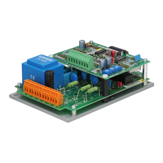
- Seite 4 Funktionselemente: Bauteilkennzeichnung Bauteilbezeichnung Bestückungsplätze R101 - R103 zur Netzanpassung Elektroniksicherung Leistungsanschlüsse Steuerklemmen Trimmer für U und U Tänzer Drahtbrücke zur Netzanpassung...
- Seite 5 Diese Dokumentation ist gültig für ..Spannungssteller 712 ab der Typenschildbezeichnung: Produktreihe Spannungssteller 712 712 = 6.6 kW Ausführung Einbaugerät Hardwarestand EDB712 DE/EN 2.1...
-
Seite 6: Dokumenthistorie
12/2008 TD29 Neuauflage wegen Neuorganisation des Unter- .=A7 nehmens 03/2010 TD00 Neue Adresse 0Abb. 0Tab. 0 Tipp! Dokumentationen und Software-Updates zu weiteren Lenze Produkten finden Sie im Internet im Bereich ”Services & Downloads” unter http://www.Lenze.com EDB712 DE/EN 2.1... -
Seite 7: Inhaltsverzeichnis
Allgemeine Sicherheits- und Anwendungshinweise für Lenze-Antriebssteller ........ - Seite 8 Inhalt Wartung/Reparatur ..........Anhang .
-
Seite 9: Vorwort Und Allgemeines
Vorwort und Allgemeines Vorwort und Allgemeines Mit dem Spannungssteller 712lassen sich Drehstromasynchronmotoren mit Wi- derstandsläuferverhalten bis zu einer Leistung von 3.3 kVA stufenlos im Dreh- moment stellen. Das Drehmoment wird beeinflusst über eine Veränderung des Schlupfes durch Phasenanschnittsteuerung der Ständerspannung. Dieser Spannungssteller stimmt mit geltenden EG-Richtlinien überein und ei- gnet sich zum Aufbau von CE-konformen Antriebssystemen. -
Seite 10: Sicherheitshinweise
Sicherheitshinweise Allgemeine Sicherheits- und Anwendungshinweise für Lenze-Antriebssteller Sicherheitshinweise Allgemeine Sicherheits- und Anwendungshinweise für Lenze-Antriebssteller (gemäß Niederspannungsrichtlinie 2006/95/EG) Allgemein Lenze-Antriebssteller (Spannungssteller) und zugehörige Komponenten kön- nen während des Betriebs - ihrer Schutzart entsprechend - spannungsführende, auch bewegliche oder rotierende Teile haben. Oberflächen können heiß sein. - Seite 11 Gehäuse verbunden sind. Öffnungen oder Durchbrüche durch das Ge- häuse auf ein Minimum reduzieren. Lenze-Antriebssteller können einen Gleichstrom im Schutzleiter verursachen. Wird für den Schutz bei einer direkten oder indirekten Berührung ein Differenz- stromgerät (RCD) verwendet, ist auf der Stromversorgungsseite des Antriebs- stellers nur ein Differenzstromgerät (RCD) vom Typ B zulässig.
- Seite 12 Sicherheitshinweise Allgemeine Sicherheits- und Anwendungshinweise für Lenze-Antriebssteller Betrieb Sie müssen Anlagen mit eingebauten Antriebsstellern ggf. mit zusätzlichen Überwachungs- und Schutzeinrichtungen gemäß den jeweils gültigen Sicher- heitsbestimmungen ausrüsten (z. B. Gesetz über technische Arbeitsmittel, Un- fallverhütungsvorschriften). Sie dürfen die Antriebssteller an Ihre Anwendung anpassen.
-
Seite 13: Restgefahren
Sicherheitshinweise Restgefahren Restgefahren Personenschutz Antriebssteller haben die Schutzart IP 00. Alle spannungsführenden Teile sind frei zugänglich. Decken Sie spannungsführende Teile ab. Dadurch verhindern Sie den ƒ unbeabsichtigten Kontakt mit lebensgefährlichen Spannungen. Schalten Sie das Netz ab, bevor Sie am Antriebssteller arbeiten. ƒ... -
Seite 14: Definition Der Verwendeten Hinweise
Sicherheitshinweise Definition der verwendeten Hinweise Definition der verwendeten Hinweise Um auf Gefahren und wichtige Informationen hinzuweisen, werden in dieser Dokumentation folgende Piktogramme und Signalwörter verwendet: Sicherheitshinweise Aufbau der Sicherheitshinweise: Gefahr! (kennzeichnet die Art und die Schwere der Gefahr) Hinweistext (beschreibt die Gefahr und gibt Hinweise, wie sie vermieden werden kann) Piktogramm und Signalwort... -
Seite 15: Technische Daten
Technische Daten Allgemeine Daten und Einsatzbedingungen Technische Daten Allgemeine Daten und Einsatzbedingungen Konformität Niederspannungsrichtlinie (2006/95/EG) EMV-Richtlinie (2004/108/EG) Verschmutzungsgrad VDE 0110 Teil 2, Verschmutzungsgrad 2 Klimatische Bedingungen nach EN 60721-3-1 bis 60721-3-4 (ohne Betauung, mittlere relative Feuchte 85 %) Lagerung 1K2 nach IEC/EN 60721-3-1 Temperatur 0 °C ... -
Seite 16: Bemessungsdaten
Technische Daten Bemessungsdaten Bemessungsdaten Antriebssteller - Baureihe 712 Typ 712 E.3B Ausgangsleistung [kW] (bezogen auf 380 V-Netzspannung) Ausgangsstrom (Dauereffektivstrom) I [A] 3 x 10 Netzfrequenz f [Hz] 50/60 Netzspannung U U [V] 190...265 L1, L2, L3 340...460 min. Spannung 0 ... 0.25 netz max. -
Seite 17: Abmessungen
Technische Daten Abmessungen Abmessungen Æ 712_001 Abb. 1 Abmessungen ∅ (mm) (mm) (mm) (mm) (mm) (mm) 712 E.3B EDB712 DE/EN 2.1... -
Seite 18: Mechanische Installation
Mechanische Installation Wichtige Hinweise Mechanische Installation Wichtige Hinweise Die Umgebungstemperatur um die Antriebssteller darf + 45°C nicht überschrei- ten. Sorgen Sie für ausreichende Belüftung, wenn Sie den Antriebssteller in ein ƒ Gehäuse einbauen. Montieren Sie den Antriebssteller senkrecht mit den Klemmen nach ƒ... -
Seite 19: Elektrische Installation
Elektrische Installation Wichtige Hinweise FI-Schutzschalter Elektrische Installation Wichtige Hinweise 5.1.1 FI-Schutzschalter Gefahr! Gefährliche elektrische Spannung Antriebssteller dieser Baureihe verfügen über einen internen Netzgleichrichter. Nach einem Körperschluss kann deshalb ein Fehlergleichstrom die Fehlerstromauslösung blockieren. Um das zu verhindern, treffen Sie folgende Maßnahmen: Nullen Sie die Anlage oder verwenden Sie allstromsensitive ƒ... -
Seite 20: Abschirmung
Elektrische Installation Wichtige Hinweise Abschirmung 5.1.3 Abschirmung Schirmen Sie alle Leitungen vom und zum Antriebssteller ab. ƒ Verbinden Sie die Abschirmung nahe der Leitungsenden mit dem ƒ zentralen Schutzleiteranschluss. 5.1.4 Erdschluss vermeiden Vor Inbetriebnahme darauf achten, daß keine Anschlussleitung einen ƒ... -
Seite 21: Emv-Gerechte Installation
Netzdrossel sowie zwischen Netzdrossel und Geschirmte Leistungsleitung mit verzinntem E-CU- Antriebssteller Geflecht mit 85 % optischer Überdeckung Motorleitungen Geschirmte Signalleitung Typ LIYCY Motor Drehstrommotor mit Widerstandsläuferverhalten Lenze Typen(reihe) ...L12, 10F4, 10F8, ...F12, ...S4, 11S6, ...S8, ...F8, 10F4, 11MF4 oder ähnlich EDB712 DE/EN 2.1... -
Seite 22: Installation Des Ce-Typischen Antriebssystem
Elektrische Installation EMV-gerechte Installation Installation des CE-typischen Antriebssystem 5.2.2 Installation des CE-typischen Antriebssystem Hinweis! Die EMV eines Antriebssystems ist installationsabhängig. Beachten Sie deshalb die Anweisungen zu Filterung, Schirmung, Erdung und Aufbau. Hinweis! Bei abweichender Installation, z.B. Verwendung ungeschirmter Leitungen ƒ... - Seite 23 Elektrische Installation EMV-gerechte Installation Installation des CE-typischen Antriebssystem Schirmung Schirmen Sie alle Leitungen zum und vom Antriebssteller ab. ƒ – Verbinden Sie den Schirm der Motorleitung nahe dem Antriebssteller großflächig mit der Montageplatte. Verwenden Sie dabei Erdungsschellen auf metallisch blanken Montageflächen. –...
- Seite 24 Elektrische Installation EMV-gerechte Installation Installation des CE-typischen Antriebssystem 4xx_012 Abb. 2 Großflächige Schirmverbindung abgeschirmte Leitung metallisch blanke Montagefläche Schirmgeflecht Erdungsschelle Trennen Sie beim Verlegen die Motorleitung von Signal- und ƒ Netzleitungen. Klemmen Sie Netzeingang und Motorausgang auf getrennte ƒ...
-
Seite 25: Anschlussplan
Elektrische Installation Anschlussplan Antriebssteller Typ 712 für Netzanschluss 340 ... 460 V Anschlussplan 5.3.1 Antriebssteller Typ 712 für Netzanschluss 340 ... 460 V FF 16 PE L1 L2 L3 712_002 Abb. 3 Anschluss Antriebssteller 712 für Netzanschluss 340 ... 460 V Das Gerät ist werkseitig auf den Netzspannungsbereich 340 ... -
Seite 26: Antriebssteller Typ 712 Für Netzanschluss 190
Elektrische Installation Anschlussplan Antriebssteller Typ 712 für Netzanschluss 190 ... 265 V 5.3.2 Antriebssteller Typ 712 für Netzanschluss 190 ... 265 V Hinweis! Der Antriebssteller 712 ist werkseitig für den Betrieb mit 340 ... 460 V eingerichtet. Für den Betrieb mit 190 ... 265 V müssen eine Lötbrücke verändert werden und drei 220 kΩ/0.5 W −... - Seite 27 Elektrische Installation Anschlussplan Antriebssteller Typ 712 für Netzanschluss 190 ... 265 V 712_004 Abb. 5 Umstellung des Antriebsstellers 712 auf Netzanschluss 190 ... 265 V durch Einlöten von 220 kΩ - Widerständen 3. Löten Sie drei Widerstände (220 kΩ, 0.5 W) an den vorgesehenen Bestückungsplätzen R101, R102 und R103 ein.
- Seite 28 Elektrische Installation Anschlussplan Antriebssteller Typ 712 für Netzanschluss 190 ... 265 V FF 16 PE L1 L2 L3 712_001 Abb. 6 Anschluss Antriebssteller 712 für Netzanschluss 190 ... 265 V EDB712 DE/EN 2.1...
-
Seite 29: Anschluss Von Steuersignalen An Den Antriebssteller 712
Elektrische Installation Anschlussplan Anschluss von Steuersignalen an den Antriebssteller 712 5.3.3 Anschluss von Steuersignalen an den Antriebssteller 712 12 13 14 16 17 10K / 1 W lin. Sollwertpoti Stellerfreigabe Leitspannung U = 10 V Tänzer 712_005 Abb. 7 Anschluss von Sollwertsignalen und der Stellerfreigabe Das Gerät kann über die Klemmen 7, 8 und 9 ein Sollwertsignal per ƒ... -
Seite 30: Erweiterung Des Drehmomentstellbereichs
Elektrische Installation Anschlussplan Erweiterung des Drehmomentstellbereichs 5.3.4 Erweiterung des Drehmomentstellbereichs Das Gerät ist im Auslieferungszustand für den Betrieb ohne Mittelpunktleiter eingerichtet. Hierbei beträgt der Drehmomentstellbereich ca. 1:20. Wird ein höherer Stellbereich gewünscht, so sind zwei Maßnahmen dazu erfor- derlich: Anschliessen des Mittelpunktleiters an den Sternpunkt des Motors ƒ... -
Seite 31: Inbetriebnahme
Inbetriebnahme Wichtige Hinweise Inbetriebnahme Wichtige Hinweise Gefahr! Gefährliche elektrische Spannung Die Inbetriebnahme darf nur von qualifizierten Fachkräften mit isoliertem Werkzeug vorgenommen werden. Gefahr! Zerstörung des Antriebsstellers bei Drehfeldumkehr, während der Motor noch dreht Die Drehfeldumkehr darf auf keinen Fall bei freigegebenem Steller und drehenden Motor aktiviert werden. -
Seite 32: Erstinbetriebnahme
Inbetriebnahme Erstinbetriebnahme Erstinbetriebnahme Schritt Abgleich für Sollwertvorgabe durch Poti Ergänzender Abgleich bei zusätzlichem (KLemmen 7, 8, 9 ) oder Leitspannung Einsatz eines Tänzerpotenziometers (Klemmen 7, 8 ) (Klemmen 12, 13, 14) Drehen Sie die Trimmer ”U ”, ”U ”, ”Tänzer” bis zum linken Anschlag. Stellen Sie Sollwertpoti oder Leitspannung auf Null. -
Seite 33: Wartung/Reparatur
Wartung und Reparatur Wartung/Reparatur Sicherungswechsel Die Sicherungen schützen den Antriebssteller vor unzulässigen Betriebsbe- dingungen. Im Fehlerfall müssen defekte Sicherungen gewechselt werden. Gefahr! Gefährliche elektrische Spannung Die Fehlersuche, die Fehlerbehebung, das Entfernen der Schutzabdeckung, und der Sicherungswechsel dürfen nur spannungslos von qualifizierten Fachkräften vorgenommen werden. -
Seite 34: Anhang
Anhang Zubehör Anhang Zubehör Zur Ergänzung von Antriebsstellern des Typs 712 E können Sie folgendes Zube- hör gesondert bestellen : Funkentstörfilter ƒ Leistungssicherungen ƒ Sicherungshalter ƒ Drehknopf und Skala für Sollwertpotentiometer ƒ Austauschwiderstand für Betrieb mit angeschlossenem Mittelpunktleiter ƒ Zinkoxid-Varistor (nur bei Betrieb mit einer Wendeschützschaltung) ƒ... - Seite 35 Anhang Zubehör EDB712 DE/EN 2.1...
- Seite 36 Elements: Part identifier Part designation Positions R101 - R103 for changing mains Electronic fuse Power terminals Control terminals Trimmers for U and U Tänzer (Dancer) Jumpers for changing mains...
- Seite 37 This documentation applies to ..Voltage controller 712 from the nameplate data: Product range Voltage controller 712 712 = 6.6 kW Design Built-in unit Hardware version EDB712 DE/EN 2.1...
-
Seite 38: Document History
New edition due to reorganisation of the com- .=A7 pany 03/2010 TD00 New address 0Abb. 0Tab. 0 Tipp! Documentation and software updates for further Lenze products can be found on the Internet in the ”Services & Downloads” area under http://www.Lenze.com EDB712 DE/EN 2.1... - Seite 39 ..........General safety instructions and application notes for Lenze drive controllers .
- Seite 40 Contents Maintenance/repair ..........Appendix .
-
Seite 41: Preface And General Information
Preface and general information Preface and general information Using the voltage controller 712, the torque of three-phase asynchronous motors with resistive rotor behaviour up to a power rating of 3.3 kVA can be steplessly adjusted. The torque is modified by changing the slip using phase control on the stator voltage. -
Seite 42: Safety Instructions
Safety instructions General safety instructions and application notes for Lenze drive controllers Safety instructions General safety instructions and application notes for Lenze drive controllers (as per Low voltage directive 2006/95/EC) General Lenze drive controllers (voltage controllers) and associated components can have, depending on their degree of protection, live parts or moving or rotating parts when in operation. - Seite 43 Openings or break-outs on the housing are to be reduced to a minimum. Lenze drive controllers can cause DC currents in the PE conductor. If a residual current device (RCD) is used for protection against direct or indirect physical contact, only a residual current device (RCD) of type B is allowed on the power supply side of the drive controller.
- Seite 44 Safety instructions General safety instructions and application notes for Lenze drive controllers Operation You must equip the drive controllers installed with additional monitoring equipment and protective equipment as per the applicable safety stipulations, if necessary (e.g. law on technical equipment, health and safety regulations).
-
Seite 45: Residual Hazards
Safety instructions Residual hazards Residual hazards Protection of persons Drive controllers have degree of protection IP 00. All live parts are freely accessible. Cover the live parts. In this way you will prevent unintentional contact ƒ with dangerous voltages. Switch off the mains before you work on the drive controller. ƒ... -
Seite 46: Definition Of Notes Used
Safety instructions Definition of notes used Definition of notes used The following pictographs and signal words are used in this documentation to indicate dangers and important information: Safety instructions Structure of safety instructions: Danger! (characterises the type and severity of danger) Note (describes the danger and gives information about how to prevent dangerous situations) -
Seite 47: Technical Data
Technical data General data and operating conditions Technical data General data and operating conditions Conformity Low-voltage directive (2006/95/EC) EMC directive (2004/108/EC) Degree of pollution VDE 0110 part 2, degree of pollution 2 Climatic conditions In accordance with EN 60721-3-1 to 60721-3-4 (no condensation, average relative humidity 85 %) Storage 1K2 in accordance with IEC/EN 60721-3-1... -
Seite 48: Rated Data
Technical data Rated data Rated data Drive controller - series 712 Type 712 E.3B Output power [kW] (referred to 380 V mains voltage) Output current (continuous effective current) I [A] 3 x 10 Mains frequency f [Hz] 50/60 Mains voltage U U [V] 190...265... -
Seite 49: Dimensions
Technical data Dimensions Dimensions Æ 712_001 Fig. 1 Dimensions ∅ Type (mm) (mm) (mm) (mm) (mm) (mm) 712 E.3B EDB712 DE/EN 2.1... -
Seite 50: Mechanical Installation
Mechanical installation Important notes Mechanical installation Important notes The ambient temperature for the drive controller must not exceed + 45°C. Provide adequate ventilation if you install the drive controller in a ƒ housing. Mount the drive controller vertical with the terminals pointing ƒ... -
Seite 51: Electrical Installation
Electrical installation Important notes Earth-leakage circuit breaker Electrical installation Important notes 5.1.1 Earth-leakage circuit breaker Danger! Dangerous electrical voltage Drive controllers in this series have an internal mains rectifier. For this reason, after a short circuit to frame a DC leakage current can block the leakage current tripping. -
Seite 52: Shielding
Electrical installation Important notes Shielding 5.1.3 Shielding Shield all wires to and from the drive controller. ƒ Connect the shield near to the ends of the wires to the central earth wire ƒ connection. 5.1.4 Prevent earth fault Prior to commissioning, ensure there are no connection cables with earth ƒ... -
Seite 53: Emc-Compliant Installation
85 % visual coverage Motor cables Shielded signal cable type LIYCY Motor Three-phase AC motor with resistive rotor behaviour Lenze type (series) ...L12, 10F4, 10F8, ...F12, ...S4, 11S6, ...S8, ...F8, 10F4, 11MF4 or similar EDB712 DE/EN 2.1... -
Seite 54: Installation Of A Ce-Typical Drive System
Electrical installation EMC-compliant installation Installation of a CE-typical drive system 5.2.2 Installation of a CE-typical drive system Note! The EMC characteristics of a drive system are installation-dependent. For this reason pay attention to the instructions on filtering, shielding, earthing and layout. ... - Seite 55 Electrical installation EMC-compliant installation Installation of a CE-typical drive system Shielding Shield all wires from and to the drive controller. ƒ – Connect the shield on the motor cable to the mounting plate near the drive controller using a large area connection. Use earthing clamps on bare metal mounting surfaces.
- Seite 56 Electrical installation EMC-compliant installation Installation of a CE-typical drive system 4xx_012 Fig. 2 Large area shield connection Shielded cable Bare metal mounting areas Braid Earthing clamp When laying cables, lay motor cable separately from signal and mains ƒ...
-
Seite 57: Connection Plan
Electrical installation Connection plan Drive controller type 712 for mains connection 340 ... 460 V Connection plan 5.3.1 Drive controller type 712 for mains connection 340 ... 460 V FF 16 PE L1 L2 L3 712_002 Fig. 3 Connection, drive controller 712 for mains connection 340 ... 460 V The device is set in the factory to a mains voltage range of ƒ... -
Seite 58: Drive Controller Type 712 For Mains Connection 190
Electrical installation Connection plan Drive controller type 712 for mains connection 190 ... 265 V 5.3.2 Drive controller type 712 for mains connection 190 ... 265 V Note! The drive controller 712 is set in the factory for operation with 340 ... - Seite 59 Electrical installation Connection plan Drive controller type 712 for mains connection 190 ... 265 V 712_004 Fig. 5 Modification of the drive controller 712 to 190 ... 265 V mains connection by soldering 220 kΩ resistors 3. Solder three resistors (220 kΩ, 0.5 W) in positions R101, R102 and R103. 4.
- Seite 60 Electrical installation Connection plan Drive controller type 712 for mains connection 190 ... 265 V FF 16 PE L1 L2 L3 712_001 Fig. 6 Connection, drive controller 712 for mains connection 190 ... 265 V EDB712 DE/EN 2.1...
- Seite 61 Electrical installation Connection plan Connection of control signals to the drive controller 712 5.3.3 Connection of control signals to the drive controller 712 12 13 14 16 17 10K / 1 W lin. Setpoint Controller potentiometer enable Master voltage U = 10 V Dancer 712_005 Fig.
-
Seite 62: Expansion Of The Torque Setting Range
Electrical installation Connection plan Expansion of the torque setting range 5.3.4 Expansion of the torque setting range As supplied the device is setup for operation without a neutral conductor. In this case the torque setting range is approx. 1:20. If a larger setting range is required, two measures must be taken: Connect the neutral conductor to the motor star point ƒ... -
Seite 63: Commissioning
Commissioning Important notes Commissioning Important notes Danger! Dangerous electrical voltage Commissioning is only allowed to be undertaken by qualified skilled personnel using insulated tools. Danger! Damage to the drive controller on field reversal if motor is still running Under no circumstances is field reversal allowed to be activated with the controller enabled and the motor rotating. -
Seite 64: Initial Commissioning
Commissioning Initial commissioning Initial commissioning Step Adjustment for setpoint selection using Further adjustment on additional use of a potentiometer (terminals 7, 8, 9 ) or dancer potentiometer (terminals 12, 13, master voltage (terminals 7, 8 ) Turn the trimmers ”U ”, ”U ”, ”Tänzer (Dancer)”... -
Seite 65: Maintenance/Repair
Maintenance/repair Maintenance/repair Fuse replacement The fuses protect the drive controller against incorrect operating conditions. In the case of a fault, faulty fuses must be replaced. Danger! Dangerous electrical voltage Troubleshooting, fault correction, the removal of the protective cover, and the replacement of fuses are only allowed to be undertaken by qualified skilled personnel with the device electrically isolated. -
Seite 66: Accessories
Appendix Accessories Appendix Accessories You can order the following accessories separately for drive controllers of type 712 E : RFI filter ƒ Power fuses ƒ Fuse holder ƒ Rotary knob and scale for setpoint potentiometer ƒ Replacement resistor for operation with neutral conductor connected ƒ... - Seite 67 Appendix Accessories EDB712 DE/EN 2.1...
- Seite 68 © 03/2010 Lenze Automation GmbH Service Lenze Service GmbH Hans-Lenze-Str. 1 Breslauer Straße 3 D-31855 Aerzen D-32699 Extertal Germany Germany +49 (0)51 54 / 82-0 00 80 00 / 24 4 68 77 (24 h helpline) +49 (0)51 54 / 82 - 28 00 +49 (0)51 54 / 82-11 12 Lenze@Lenze.de...