Inhaltsverzeichnis
Werbung
Verfügbare Sprachen
Verfügbare Sprachen
Quicklinks
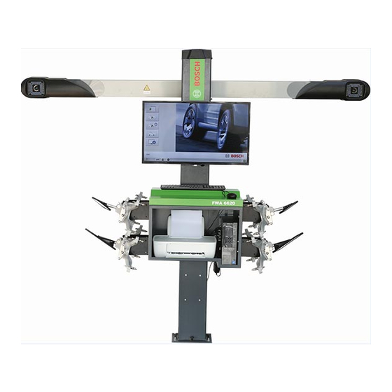
FWA 6620 / 6720 / 6820
de Originalbetriebsanleitung
3D 2cam Achsmessgerät
es Manual original
3D 2cam Indicador de alineación de
ejes
ru Pуководство по эксплуатации
3D 2cam Прибор для проверки
установки колес
en Original instructions
3D 2cam Wheel Alignment System
it Istruzioni originali
3D 2cam Sistema di controllo assetto
fr Notice originale
3D 2cam Système de contrôle de
géométrie
pl Oryginalna instrukcja eksploatacji
3D 2cam Urządzenie do pomiaru
geometrii osi
Werbung
Inhaltsverzeichnis

Verwandte Anleitungen für Bosch FWA 6620


Inhaltszusammenfassung für Bosch FWA 6620
- Seite 1 FWA 6620 / 6720 / 6820 de Originalbetriebsanleitung en Original instructions fr Notice originale 3D 2cam Achsmessgerät 3D 2cam Wheel Alignment System 3D 2cam Système de contrôle de géométrie es Manual original it Istruzioni originali pl Oryginalna instrukcja eksploatacji 3D 2cam Indicador de alineación de 3D 2cam Sistema di controllo assetto 3D 2cam Urządzenie do pomiaru...
- Seite 2 AA-AS/NE1 Harald Neumann (Development, person responsible of documents) Robert Bosch GmbH, Franz-Oechsle-Straße 4, 73207, Plochingen, DEUTSCHLAND Do kumentationsbevollmächtigter / Person authorized to compile documentation / Représentant autorisé pour la documentation / Representante legal de la documentación / Incaricato della documentazione / Befullmäktigad att sammanställa dokumentationen / Dokumentationsbefuldmægtiget / Verantwoordelijke voor de documentatie / Responsável...
- Seite 3 AA-AS/NE1 Harald Neumann (Development, person responsible of documents) Robert Bosch GmbH, Franz-Oechsle-Straße 4, 73207, Plochingen, DEUTSCHLAND Do kumentationsbevollmächtigter / Person authorized to compile documentation / Représentant autorisé pour la documentation / Representante legal de la documentación / Incaricato della documentazione / Befullmäktigad att sammanställa dokumentationen / Dokumentationsbefuldmægtiget / Verantwoordelijke voor de documentatie / Responsável...
- Seite 4 AA-AS/NE1 Harald Neumann (Development, person responsible of documents) Robert Bosch GmbH, Franz-Oechsle-Straße 4, 73207, Plochingen, DEUTSCHLAND Do kumentationsbevollmächtigter / Person authorized to compile documentation / Représentant autorisé pour la documentation / Representante legal de la documentación / Incaricato della documentazione / Befullmäktigad att sammanställa dokumentationen / Dokumentationsbefuldmægtiget / Verantwoordelijke voor de documentatie / Responsável...
-
Seite 6: Inhaltsverzeichnis
6 | FWA 6620 / 6720 / 6820 | Inhaltsverzeichnis Deutsch Contents English Sommaire Français Índice Español Indice Italiano Spis treści polski Содержание Русский 1 690 706 113 2017-10-11 Robert Bosch GmbH... -
Seite 7: Inhaltsverzeichnis Deutsch
| FWA 6620 / 6720 / 6820 | 7 Inhaltsverzeichnis Deutsch Programmgeführte Vermessung 5.7.1 Kunde neu anlegen Verwendete Symbolik 5.7.2 Fahrzeug neu anlegen In der Dokumentation 5.7.3 Kunde wählen 1.1.1 Warnhinweise – Aufbau und Bedeutung 5 5.7.4 Fahrzeug wählen 1.1.2 Symbole –... -
Seite 8: Verwendete Symbolik
8 | FWA 6620 / 6720 / 6820 | Verwendete Symbolik Verwendete Symbolik Benutzerhinweise In der Dokumentation Wichtige Hinweise 1.1.1 Warnhinweise – Aufbau und Bedeutung Wichtige Hinweise zur Vereinbarung über Urheberrecht, Warnhinweise warnen Benutzer oder umstehende Perso- Haftung und Gewährleistung, über die Benutzergruppe nen vor Gefahren. -
Seite 9: Produktbeschreibung
Produktbeschreibung | FWA 6620 / 6720 / 6820 | 9 Produktbeschreibung 3.2.2 FWA 6720 FWA 6720 besteht aus einen PC auf einem fahrbaren Bestimmungsgemäße Verwendung Gerätewagen, Kamerabalken, Standsäule, Anschlusska- FWA 6620 / 6720 / 6820 ist nur zur Fahrwerkvermes- bel und Messtafeln. - Seite 10 10 | FWA 6620 / 6720 / 6820 | Produktbeschreibung Komponenten 3.2.3 FWA 6820 FWA 6820 besteht aus einen PC auf einem fahrbaren Bezeichnung Beschreibung Gerätewagen, Kamerabalken, Standsäule, Anschlusska- Kamerabalken Der Kamerabalken enthält die beiden 3D-Ka- bel und Messtafeln. meras. Der Kamerabalken ist an der Stand- Höhenanpassung Kamerabalken:...
-
Seite 11: Übersicht Messmöglichkeiten
Produktbeschreibung | FWA 6620 / 6720 / 6820 | 11 Erstinbetriebnahme Übersicht Messmöglichkeiten Der Betrieb von FWA 6620 / 6720 / 6820 muss mit ei- Gesamtspur (VA + HA) ner Hebebühne oder Grube erfolgen. Um eine korrekte Einzelspur (VA + HA) Messung zu ermöglichen, müssen spezielle Anforderun-... -
Seite 12: Vorbereitung
12 | FWA 6620 / 6720 / 6820 | Vorbereitung Vorbereitung 4.1.2 Prüfung Hebebühne ¶ Beim Arbeiten mit der Hebebühne auf gleiches Ni- Messplatz veau der Messhöhe und Arbeitshöhe achten. ¶ Drehuntersätze und Schiebuntersätze müssen an der Messstelle Zulässige Hebebühne befestigt sein. -
Seite 13: Auf Messplatz Fahren
Vorbereitung | FWA 6620 / 6720 / 6820 | 13 Auf Messplatz fahren Universal-Spannhalter befestigen Beim Auffahren des Fahrzeugs auf den Messplatz Nach Abstellen des Fahrzeugs auf der Hebebühne müssen die Sicherungsstifte am Drehuntersatz muss das Vorderrad auf dem gesicherten Drehunter- und den Schiebeplatten eingesteckt sein. -
Seite 14: Messtafeln Montieren
14 | FWA 6620 / 6720 / 6820 | Vorbereitung Messtafeln montieren Mit dem Drehknopf der Gewindespindel wird der Universal-Spannhalter schnell von innen nach außen und von außen nach innen in der Mittelachse der Felge zentriert und auf die Felge gespannt. -
Seite 15: Bremsspanner Montieren Und Demontieren
Vorbereitung | FWA 6620 / 6720 / 6820 | 15 Bremsspanner montieren und Lenkradfeststeller montieren und demontieren demontieren Mit dem Lenkradfeststeller wird bei den Einstellarbei- ten das Lenkrad fixiert und die Räder blockiert. 1. Lenkradfeststeller auf dem Sitz abstellen und den Teller in den Sitz drücken. -
Seite 16: Bedienung
Bedienung Kamerabalken ausrichten Einschalten und Ausschalten 5.2.1 Vorbereitung 1. FWA 6620 / 6720 / 6820 über den Hauptschalter an der Steckdosenleiste innerhalb des Gerätewagens Zwischen Kamerabalken und Hebebühne oder einschalten. Grubenarbeitsfläche eine Höhe von etwa 700 mm 2. PC mit dem Schalter auf der Vorderseite einschal- einhalten. -
Seite 17: Manuell Ausrichten
Bedienung | FWA 6620 / 6720 / 6820 | 17 1. Im Fenster "Programmeinstellungen / Wartung" das 5. Programmfenster "Achsmessgeräteprüfung" öffnet. Feld "Kalibrierung" wählen. Abb. 19: Messtafeln Erkennung Abb. 16: Programmfenster Kalibrierung Dialogfenster zur Passworteingabe öffnet. Prüfung der Bildschirmanzeige, bis alle Messtafeln farbige Linien haben: ... -
Seite 18: Tastenfunktion
18 | FWA 6620 / 6720 / 6820 | Bedienung Tastenfunktion Programmstruktur Taste Funktion Taste Funktion 5.5.1 Programmfunktionen Messung zurückset- Hilfe zen. Symbol Funktion Rückwärts Drucken Sichtprüfung Vorwärts Messung angeho- Programmgeführte Vermessung Zurück zum Haupt- Strg + F3 Felgenschlag-Kom- menü... -
Seite 19: Sichtprüfung
Bedienung | FWA 6620 / 6720 / 6820 | 19 Sichtprüfung Programmgeführte Vermessung ¶ Vor der Achsvermessung Sichtprüfung durchführen. wählen: Programmgeführte Vermessung startet. ¶ Eingabefenster öffnet. wählen: Programmfenster Sichtprüfung startet. Mit der Sichtprüfung kontrollieren, welche Teile des Fahrzeugs beschädigt oder verschlissen sind. - Seite 20 20 | FWA 6620 / 6720 / 6820 | Bedienung 5.7.1 Kunde neu anlegen 5.7.3 Kunde wählen wählen: In Kundenliste suchen Fenster zur Eingabe der Kundendaten öffnet. 1. Den Kundennamen Suchfeld der Kundenliste den Kundendaten eingeben. Kundennamen eingeben.
-
Seite 21: Fahrzeug Wählen
Bedienung | FWA 6620 / 6720 / 6820 | 21 5.7.4 Fahrzeug wählen 5.7.5 Messtafeln ausrichten In Kennzeichenliste suchen 1. Das Kennzeichen im Suchfeld der Kennzeichenliste eingeben. Abb. 29: Eingabefeld Suche neben Suchfeld wählen: Kennzeichen und Kunde werden angezeigt. -
Seite 22: Felgenschlag Kompensieren
22 | FWA 6620 / 6720 / 6820 | Bedienung 5.7.6 Felgenschlag kompensieren Der Ablauf kann auch anhand der LED-Anzeigen neben 1. Feststellbremse lösen. den Kameras gesehen werden. 2. Sicherungsseil Universal-Spannhalter an der Felge Eine Zeile zeigt die Bewegungsrichtung, die andere Zei- aushängen. -
Seite 23: Einschlagroutine
Bedienung | FWA 6620 / 6720 / 6820 | 23 5.7.7 Einschlagroutine 3. Lenkung nach links drehen. 4. Von Mittelstellung Lenkung 20 0 oder 10 0 (je nach Messung des Nachlaufs, der Spreizung und des Programmeinstellung) nach rechts drehen. Lenkmittelpunkts. Während der Messung des Nachlaufs den Brems- spanner montieren, damit unerwünschte Bewegun-... -
Seite 24: Vorderachswerte Messen
24 | FWA 6620 / 6720 / 6820 | Bedienung 5.7.8 Hinterachswerte messen 5.7.10 Vorderachswerte messen 1. Lenkrad in Mittelstellung bringen. 2. Lenkradfeststeller einsetzen. 3. <Weiter> wählen: Abb. 48: Vorderachswerte Der Messbildschirm zeigt die Werte für Sturz, Spur und Gesamtspur an. -
Seite 25: Messprotokoll Drucken
Bedienung | FWA 6620 / 6720 / 6820 | 25 Schnellvermessung 5.7.12 Messprotokoll drucken 1. Hauptmenü aufrufen. Die Messwerte werden den Sollwerten des Herstel- lers gegenübergestellt. 1. <F3> wählen. Vorschau des Messprotokolls wird angezeigt. wählen: Messergebnisse werden ausgedruckt. -
Seite 26: Wahlfreie Vermessung
26 | FWA 6620 / 6720 / 6820 | Bedienung Wahlfreie Vermessung 5.8.4 Bildschirmübersicht prüfen Nach einem erfolgreichen Messvorgang werden die 5.9.1 Messung wählen Live-Werte der Vorderachse und Hinterachse ange- 1. Hauptmenü aufrufen. zeigt. Abb. 55: Hauptmenü Abb. 52: Zentrieren des Lenkrads und Verriegelung der Bremse wählen:... - Seite 27 Bedienung | FWA 6620 / 6720 / 6820 | 27 Wahlfreie Vermessung beinhaltet folgende Routinen: Bildschirmübersicht für Vorderachse und Hinterachse R Einzelspur und Gesamtspur. R Sturz R Spurdifferenzwinkel. R Messung und Einstellung von Sturz und Spur im angehobenen Zu- stand.
-
Seite 28: Programmeinstellungen
28 | FWA 6620 / 6720 / 6820 | Bedienung 5.10 Programmeinstellungen 5.10.2 Versionsinfo 1. Hauptmenü aufrufen. ¶ wählen: Fenster "Versionsinfo" öffnet. Ausführliche Versionsinformationen werden an- gezeigt. Abb. 58: Hauptmenü wählen: Fenster "Programmeinstellungen" öffnet. Abb. 60: Versionsinfo 5.10.1... -
Seite 29: Kalibrierung
Bedienung | FWA 6620 / 6720 / 6820 | 29 5.10.4 Kalibrierung 5.10.5 Datenbankverwaltung wählen: wählen: Fenster Passwortabfrage öffnet. Fenster Passwortabfrage öffnet. Abb. 62: Eingabefenster Passwort Abb. 64: Eingabefenster Passwort Passwort = admin. Passwort = admin. 2. <F3> oder <enter> wählen: 4. -
Seite 30: Werkstattadresse Eingeben
30 | FWA 6620 / 6720 / 6820 | Bedienung 5.10.6 Werkstattadresse eingeben wählen: Fenster "Werkstattadresse" öffnet. Daten der Werkstattadresse einfügen. Abb. 66: Eingabefenster Werkstattadresse 1 690 706 113 2017-10-11 Robert Bosch GmbH... -
Seite 31: Instandhaltung
Instandhaltung | FWA 6620 / 6720 / 6820 | 31 Instandhaltung Entsorgung Reinigung FWA 6620 / 6720 / 6820, Zubehör und Verpa- ckungen sollen einer umweltgerechten Wie- 6.1.1 Gerätewagen derverwertung zugeführt werden. ¶ ¶ Gerätewagen und Monitor nur mit weichen Tüchern FWA 6620 / 6720 / 6820 nicht in den Haus- und neutralen Reinigungsmitteln reinigen. - Seite 32 32 | FWA 6620 / 6720 / 6820 | Bedienung Hinweis bei Störungen Beschreibung Mögliche Ursache Behebung Achsmessgerät - keine Strom Spannungsversorgung prüfen. Bildschirmanzeige. Netzanschlussleitung Leitungsanschluss prüfen, Leitung prüfen und wechseln. Monitor nicht eingeschaltet. Sicherung prüfen. Monitor oder Grafikkarte defekt.
-
Seite 33: Technische Daten
Technische Daten | FWA 6620 / 6720 / 6820 | 33 Technische Daten Messbereiche Messmöglichkeiten Messbereich Gesamtspur (VA + HA) ±50 ° Einzelspur (VA + HA) ±25 ° Sturz (VA + HA) ±15 ° Radversatz (VA + HA) ±9 ° Fahrachswinkel ±9 ° Nachlauf ±22 °... -
Seite 34: Contents English
34 | FWA 6620 / 6720 / 6820 | Contents English Program-driven measurement 5.7.1 Creating a new customer Symbols used 5.7.2 Creating a new vehicle In the documentation 5.7.3 Selecting a customer 1.1.1 Warning notices - 5.7.4 Selecting a vehicle Structure and meaning 5.7.5... -
Seite 35: Symbols Used
Wheel Test Equipment". These instructions must be care- Warning notices have the following structure: fully studied prior to start-up, connection and operation of the FWA 6620 / 6720 / 6820 and must always be hee- KEY WORD – Nature and source of hazard! ded. -
Seite 36: Product Description
FWA 6720 consists of a PC/laptop on a moveable trol- Intended use ley, camera beams, post, power supply cable and mea- The FWA 6620 / 6720 / 6820 is only to be used for surement boards. wheel alignment on passenger cars and light commer- Height adjustment camera beam: ¶... - Seite 37 Product description | FWA 6620 / 6720 / 6820 | 37 Components 3.2.3 FWA 6820 FWA 6820 consists of a PC/laptop on a moveable trol- Denomination Description ley, camera beams, post, power supply cable and mea- Camera beam The camera beam includes both 3D came- surement boards.
-
Seite 38: Initial Commissioning
38 | FWA 6620 / 6720 / 6820 | Product description Initial commissioning Measurement options The FWA 6620 / 6720 / 6820 is to be operated in con- Total toe (front axle + rear axle) junction with a lift or over a pit. In order to ensure... -
Seite 39: Checking The Vehicle
Preparation | FWA 6620 / 6720 / 6820 | 39 Preparation 4.1.2 Checking the lift ¶ When using a vehicle lift, make sure the measuring Measurement bay and working height are identical. ¶ The turntables and sliding bases must be fastened... - Seite 40 40 | FWA 6620 / 6720 / 6820 | Preparation Driving to the measurement bay Fastening the universal clamp The securing pins and the sliding plates must be After parking the vehicle on lift, the front wheel inserted on the turntable when driving the vehicle to must sit on the secured turntable.
- Seite 41 Preparation | FWA 6620 / 6720 / 6820 | 41 Mounting the measurement boards By way of the rotary knob of the threaded spindle, the universal clamp is quickly be centered from inside to outside and from outside to inside in the center axis of the rim and clamped to the rim.
- Seite 42 42 | FWA 6620 / 6720 / 6820 | Preparation Mounting and removing brake clamps Mounting and removing the steering wheel arrester The steering wheel arrester fixes the steering wheel in position when performing adjustment work and blocks the wheels.
-
Seite 43: Switching On And Off
Aligning the camera beam Switching on and off 5.2.1 Preparation 1. Switch on the FWA 6620 / 6720 / 6820 by way of the on/off switch on the multiple socket inside of the Keep an approximate height distance of 700 mm trolley. - Seite 44 44 | FWA 6620 / 6720 / 6820 | Operation 1. Select the input box "Calibration" in the window 5. Program window "Wheel alignment test" is opened. "Program settings / maintenance". Abb. 19: Measurement board recognition Abb. 16: Program window "Calibration"...
-
Seite 45: Key Function
Operation | FWA 6620 / 6720 / 6820 | 45 Key function Program structure Function Function 5.5.1 Program functions Reset measurement. Help Icon Function Backwards Print Forwards Measurement Visual inspection raised Back to the main me- Ctrl + F3 Deactivate run-out... -
Seite 46: Visual Inspection
46 | FWA 6620 / 6720 / 6820 | Operation Visual inspection Program-driven measurement ¶ Perform visual inspection prior to the wheel align- Select Program-driven measurement is started. ment. Input window is opened. ¶ Select Program window visual inspection is started. - Seite 47 Operation | FWA 6620 / 6720 / 6820 | 47 5.7.1 Creating a new customer 5.7.3 Selecting a customer 1. Select Search in customer list Window for customer data entry is opened. 1. Enter the customer name in the search field of the ...
- Seite 48 48 | FWA 6620 / 6720 / 6820 | Operation 5.7.4 Selecting a vehicle 5.7.5 Aligning the measurement boards Search in license plate list 1. Enter the license plate in the search field of the license plate list. Abb. 29: Input box search 2.
- Seite 49 Operation | FWA 6620 / 6720 / 6820 | 49 5.7.6 Compensating the run-out The process can also be viewed by way of the LED dis- 1. Release parking brake. play next to the cameras. 2. Disengage the securing cable of the universal clamp One line displays the direction of movement, the other at the rim.
- Seite 50 50 | FWA 6620 / 6720 / 6820 | Operation 5.7.7 Steering angle routine 3. Turn steering to left. 4. From center position, turn steering to the right by Castor, steering axis inclination and steering center 20 0 or 10 0 (depending on program setting).
-
Seite 51: Adjust In Raised Position
Operation | FWA 6620 / 6720 / 6820 | 51 5.7.8 Measuring the rear axle value 5.7.10 Measuring front axle values 1. Bring steering wheel in center position. 2. Insert the steering wheel arrester. 3. Select <Continue>: Abb. 48: Front axle values ... - Seite 52 52 | FWA 6620 / 6720 / 6820 | Operation Quick measurement 5.7.12 Printing the test protocol 1. Call up main menu. The measurement values are compared to the manufacturer's setpoint values. 1. Select <F3>. Preview of the test protocol is displayed.
- Seite 53 Operation | FWA 6620 / 6720 / 6820 | 53 Random measurement 5.8.4 Checking the display overview Following a successful measurement process, the 5.9.1 Selecting a measurement live values of front and rear axle are displayed. 1. Call up main menu.
- Seite 54 54 | FWA 6620 / 6720 / 6820 | Operation Random measurement contains the following routines: Screen overview for front and rear axle R Individual toe and total toe. R Camber R Toe-out on turns. R Measurement and adjustment of camber and toe in lifted condition.
-
Seite 55: Program Settings
Operation | FWA 6620 / 6720 / 6820 | 55 5.10 Program settings 5.10.2 Version Info 1. Call up main menu. ¶ Select Dialog box "Version Info" is opened. Extended version information is displayed. Abb. 58: Main menu 2. - Seite 56 56 | FWA 6620 / 6720 / 6820 | Operation 5.10.4 Calibration 5.10.5 Database management 1. Select 3. Select Dialog box Password prompt is opened. Dialog box Password prompt is opened. Abb. 62: Password input window Abb. 64: Password input window Password = admin.
- Seite 57 Operation | FWA 6620 / 6720 / 6820 | 57 5.10.6 Entering the workshop address 1. Select Dialog box "Workshop address" is opened. Enter workshop address data. Abb. 66: Input window Workshop address Robert Bosch GmbH 1 690 706 113...
-
Seite 58: Ultrasonic Cleaning
Only for EC countries: ¶ Use a special fiber cloth to clean the monitor. The FWA 6620 / 6720 / 6820 is subject to the Disconnect the voltage supply prior to cleaning. European directive 2012/19/EC (WEEE). Don't wipe electrical components with wet cloth. -
Seite 59: Instructions In Case Of Faults
Maintenance | FWA 6620 / 6720 / 6820 | 59 Instructions in case of faults Description Possible cause Remedy Wheel alignment sys- Power Test the voltage supply. tem - none Power supply cable Check the line connection and cables, and exchange. -
Seite 60: Technical Data
60 | FWA 6620 / 6720 / 6820 | Technical Data Technical Data Measuring ranges Measurement options Measuring range Total toe (front axle + rear axle) ±50 ° Individual toe (front axle + rear axle) ±25 ° Camber (front axle + rear axle) ... -
Seite 61: Sommaire Français
| FWA 6620 / 6720 / 6820 | 61 Sommaire Français Contrôle guidé par le programme 5.7.1 Créer un nouveau client Symboles utilisés 5.7.2 Créer un nouveau véhicule Dans la documentation 5.7.3 Sélectionner le client 1.1.1 Avertissements – Conception 5.7.4 Sélectionner un véhicule... -
Seite 62: Symboles Utilisés
Bosch Wheel Test Equipment". Avant la mise en service, le raccordement et l'utilisation MOT CLÉ - Nature et source du danger ! du FWA 6620 / 6720 / 6820 il est impératif de lire et Symbole d’avertisse- d'appliquer ces consignes. -
Seite 63: Description Du Produit
Description du produit | FWA 6620 / 6720 / 6820 | 63 Description du produit 3.2.2 FWA 6720 Le FWA 6720 est composé d'un PC dans chariot mobile, Utilisation conforme une barre porte-caméras, une colonne, un câble de rac- Le FWA 6620 / 6720 / 6820 doit être utilisé uniquement cordement et des panneaux de mesure. - Seite 64 64 | FWA 6620 / 6720 / 6820 | Description du produit Composants 3.2.3 FWA 6820 Le FWA 6820 est composé d'un PC dans chariot mobile, Désignation Description une barre porte-caméras, une colonne, un câble de rac- Barre porte-ca- La barre porte-caméras comprend les deux cordement et des panneaux de mesure.
-
Seite 65: Première Mise En Service
Description du produit | FWA 6620 / 6720 / 6820 | 65 Première mise en service Vue d’ensemble des possibilités de mesure Le FWA 6620 / 6720 / 6820 doit être utilisé avec un pont élévateur ou une fosse. Pour permettre une me- Parallélisme total (AV + AR) - Seite 66 66 | FWA 6620 / 6720 / 6820 | Préparation Préparation 4.1.2 Contrôle du pont élévateur ¶ Lors du l'utilisation du pont élévateur, veiller à ce Emplacement de mesure que la hauteur de mesure et la hauteur de travail soient au même niveau.
- Seite 67 Préparation | FWA 6620 / 6720 / 6820 | 67 Conduire le véhicule sur Fixer le support à serrage universel l'emplacement de mesure Après avoir immobilisé le véhicule sur le pont Lors de l'avancée du véhicule sur l'emplacement de élévateur, la roue avant doit être sur l'appui rotatif mesure, les goupilles de fixation doivent être enfi-...
- Seite 68 68 | FWA 6620 / 6720 / 6820 | Préparation Monter les panneaux de mesure Le bouton rotatif de la vis de serrage permet de centrer le support à serrage universel rapidement de l'intérieur vers l'extérieur et de l'extérieur vers l'intérieur dans l'axe de la jante et de le serrer sur la...
- Seite 69 Préparation | FWA 6620 / 6720 / 6820 | 69 Monter et démonter le système de Monter et démonter le bloque-volant serrage de frein Le dispositif de blocage du volant permet de fixer le volant pendant les réglages et de bloquer les roues.
-
Seite 70: Allumer Et Éteindre
Orienter la barre porte-caméras Allumer et éteindre 5.2.1 Préparation 1. Mettre le FWA 6620 / 6720 / 6820 en marche avec l'interrupteur principal sur la rallonge multiprises Respecter une hauteur d'environ 700 mm entre la dans le chariot. barre porte-caméras et le pont élévateur ou une 2. - Seite 71 Utilisation | FWA 6620 / 6720 / 6820 | 71 1. Dans la fenêtre "Réglages de programme / Entreti- 5. La fenêtre du programme "Contrôle du système de en", sélectionner le champ "Calibrage". contrôle de géométrie" s'ouvre. Abb. 16: Fenêtre de programme Calibrage Abb.
-
Seite 72: Structure Du Programme
72 | FWA 6620 / 6720 / 6820 | Utilisation Fonction de touche Structure du programme Tou- Fonction Touche Fonction 5.5.1 Fonctions de programme Réinitialiser la mesure. F5 Aide Symbole Fonction En arrière Imprimer Contrôle visuel Suivant Mesure en pos. sou- levée... -
Seite 73: Contrôle Visuel
Utilisation | FWA 6620 / 6720 / 6820 | 73 Contrôle visuel Contrôle guidé par le programme ¶ Exécuter un contrôle visuel avant le contrôle de Sélectionner : Le contrôle guidé par le programme démarre. géométrie. La fenêtre de saisie s'ouvre. - Seite 74 74 | FWA 6620 / 6720 / 6820 | Utilisation 5.7.1 Créer un nouveau client 5.7.3 Sélectionner le client 1. Sélectionner : Rechercher dans la liste des clients La fenêtre pour la saisie des données client s'ouvre. 1. Saisir le nom du client dans le champ de recherche ...
- Seite 75 Utilisation | FWA 6620 / 6720 / 6820 | 75 5.7.4 Sélectionner un véhicule 5.7.5 Ajuster les panneaux de mesure Rechercher dans la liste des immatriculations 1. Saisir l'immatriculation dans le champ de recherche de la liste des immatriculations. Abb. 29: Champ de saisie Recherche 2.
- Seite 76 76 | FWA 6620 / 6720 / 6820 | Utilisation 5.7.6 Compensation du voile de jante Le déroulement peut également être vu au moyen des 1. Desserrer le frein de stationnement. affichages LED à côté des caméras. 2. Décrocher le câble de sécurité du support à serrage Une ligne montre le sens de déplacement, l'autre ligne...
- Seite 77 Utilisation | FWA 6620 / 6720 / 6820 | 77 5.7.7 Routine de braquage 3. Braquer vers la gauche. 4. A partir de la position médiane de braquage 20 0 ou Mesure du post-fonctionnement, de l'angle 10 0 (selon le réglage du programme), tourner vers d'inclinaison de l'axe de pivot et de la position médi-...
- Seite 78 78 | FWA 6620 / 6720 / 6820 | Utilisation 5.7.8 Mesurer les valeurs de l'essieu arrière 5.7.10 Mesurer les valeurs relatives à l'essieu avant 1. Amener le volant en position médiane. 2. Utiliser le bloque-volant. 3. Sélectionner <Suivant> : Abb. 48: Valeurs relatives à l'essieu avant ...
- Seite 79 Utilisation | FWA 6620 / 6720 / 6820 | 79 Contrôle rapide 5.7.12 Imprimer le protocole de mesure 1. Ouvrir le menu principal. Les valeurs mesurées sont comparées avec les va- leurs de consigne du fabricant. 1. Sélectionner <F3>. L'aperçu du protocole de mesure est affiché.
- Seite 80 80 | FWA 6620 / 6720 / 6820 | Utilisation Mesure libre 5.8.4 Vérifier la vue d'ensemble de l'écran Après la procédure de mesure, les valeurs actuelles 5.9.1 Sélectionner la mesure de l'essieu avant et de l'essieu arrière sont affichées.
- Seite 81 Utilisation | FWA 6620 / 6720 / 6820 | 81 Le contrôle libre contient les routines suivantes : Vue d'ensemble d'écran pour essieu avant et essieu arrière R Parallélisme individuel et parallélisme total. R Carrossage R Divergence de braquage. R Mesure et réglage de carrossage et de parallélisme à l'état soulevé.
-
Seite 82: Info Version
82 | FWA 6620 / 6720 / 6820 | Utilisation 5.10 Réglages de programme 5.10.2 Info version 1. Ouvrir le menu principal. ¶ Sélectionner : La fenêtre "Info version" est ouverte. Des informations de version détaillées sont affichées. -
Seite 83: Gestion De La Base De Données
Utilisation | FWA 6620 / 6720 / 6820 | 83 5.10.4 Calibrage 5.10.5 Gestion de la base de données 1. Sélectionner : 3. Sélectionner : La fenêtre de demande de mot de passe s'ouvre. La fenêtre de demande de mot de passe s'ouvre. - Seite 84 84 | FWA 6620 / 6720 / 6820 | Utilisation 5.10.6 Saisir l’adresse de l’atelier 1. Sélectionner : La fenêtre "Adresse d'atelier" s'ouvre. Ajouter les données de l'adresse d'atelier. Abb. 66: Fenêtre de saisie Adresse d'atelier 1 690 706 113...
-
Seite 85: Pièces De Rechange Et D'usure
Uniquement pour les pays de l'UE: ¶ Nettoyer l'écran avec un chiffon fibreux spécial. Le FWA 6620 / 6720 / 6820 est soumis à la Avant le nettoyage, couper l'alimentation en tension. directive européenne 2012/19/CE (DEEE). Ne pas essuyer les composants électroniques avec Les appareils électriques et électroniques... -
Seite 86: Remarque En Cas De Défauts
86 | FWA 6620 / 6720 / 6820 | Utilisation Remarque en cas de défauts Description Cause possible Remède Système de contrôle Courant Contrôler l'alimentation en tension. de géométrie - aucun Cordon secteur Vérifier le raccordement des câbles, vérifier et remplacer le câble. -
Seite 87: Caractéristiques Techniques
Caractéristiques techniques | FWA 6620 / 6720 / 6820 | 87 Caractéristiques tech- niques Plages de mesure Possibilités de mesure Plage de mesure Parallélisme total (AV + AR) ±50 ° Parallélisme individuel (AV + AR) ±25 ° Carrossage (AV + AR) ±15 ° Décalage des roues (AV + AR) ±9 ° Angle de poussée ±9 °... -
Seite 88: Índice Español
88 | FWA 6620 / 6720 / 6820 | Índice Español Alineación realizada por el programa 5.7.1 Crear nuevo cliente Símbolos empleados 5.7.2 Crear nuevo vehículo En la documentación 5.7.3 Seleccionar cliente 1.1.1 Advertencias: estructura y significado 86 5.7.4 Seleccionar vehículo 1.1.2... -
Seite 89: Símbolos Empleados
Símbolos empleados | FWA 6620 / 6720 / 6820 | 89 Símbolos empleados Indicaciones para el usuario En la documentación Indicaciones importantes 1.1.1 Advertencias: estructura y significado Encontrará indicaciones importantes relativas al acuer- Las indicaciones de advertencia advierten de peligros do sobre los derechos de autor, la responsabilidad, para el usuario o las personas circundantes. -
Seite 90: Descripción Del Producto
90 | FWA 6620 / 6720 / 6820 | Descripción del producto Descripción del producto 3.2.2 FWA 6720 El producto FWA 6720 consta de un PC sobre un car- Uso conforme a lo previsto ro portátil, travesaño con cámaras, columna soporte, El producto FWA 6620 / 6720 / 6820 solo se debe utili- cable de conexión y paneles de medición. - Seite 91 Descripción del producto | FWA 6620 / 6720 / 6820 | 91 Componentes 3.2.3 FWA 6820 El producto FWA 6820 consta de un PC sobre un car- Denominación Descripción ro portátil, travesaño con cámaras, columna soporte, Travesaño con El travesaño con cámaras tiene las dos cá- cable de conexión y paneles de medición.
-
Seite 92: Accesorios Especiales
92 | FWA 6620 / 6720 / 6820 | Descripción del producto Primera puesta en servicio del pro- Cuadro general de posibilidades de ducto medición El producto FWA 6620 / 6720 / 6820 se debe utilizar Convergencia total (eje delantero + eje trasero) con un elevador o foso. - Seite 93 Preparación | FWA 6620 / 6720 / 6820 | 93 Preparación 4.1.2 Comprobación elevador ¶ Si se trabaja con el elevador, tener en cuenta sin Puesto de medición falta que la altura de medición y la altura de trabajo tengan el mismo nivel.
- Seite 94 94 | FWA 6620 / 6720 / 6820 | Preparación Pasar al puesto de medición Fijar el soporte de fijación universal Al conducir el vehículo al puesto de medición, los Después de colocar el vehículo sobre el elevador, la pasadores del seguro de la base giratoria y las bases rueda delantera debe situarse sobre la base giratoria de deslizamiento deben estar insertados.
- Seite 95 Preparación | FWA 6620 / 6720 / 6820 | 95 Montar los paneles de medición Gracias a la perilla giratoria del tornillo tensor, el soporte de fijación universal se puede centrar rápi- damente de adentro hacia afuera y desde el exterior hacia el interior en el eje central de la llanta y fijarla a la misma.
- Seite 96 96 | FWA 6620 / 6720 / 6820 | Preparación Montar y desmontar el tensor de Montar y desmontar el fijador del freno volante Con el fijador del volante, se fija el volante y se bloque- an las ruedas durante los trabajos de ajuste.
-
Seite 97: Conexión Y Desconexión
Alinear el travesaño con cámaras Conexión y desconexión 5.2.1 Preparación 1. Conectar el producto FWA 6620 / 6720 / 6820 con el interruptor principal de la regleta de enchufes de Entre el travesaño con cámaras y el elevador o la dentro del carro. - Seite 98 98 | FWA 6620 / 6720 / 6820 | Manejo 1. En la ventana "Ajustes del programa / mantenimien- 5. Se abre la ventana de programa "Comprobación del to" seleccionar el campo "Calibración". equipo de medición de ejes". Abb. 16: Ventana del programa Calibración Abb.
-
Seite 99: Estructura Del Programa
Manejo | FWA 6620 / 6720 / 6820 | 99 Función de tecla Estructura del programa Tecla Función Tecla Función 5.5.1 Funciones del programa Restablecer la medi- Ayuda ción. Símbolo Función Atrás Imprimir Prueba visual Adelante Medición elevada Volver al menú prin-... - Seite 100 100 | FWA 6620 / 6720 / 6820 | Manejo Prueba visual Alineación realizada por el programa ¶ Realizar una prueba visual antes de la alineación del Seleccionar Comienza la alineación realizada por el programa. chasis. Se abre la ventana de entrada.
- Seite 101 Manejo | FWA 6620 / 6720 / 6820 | 101 5.7.1 Crear nuevo cliente 5.7.3 Seleccionar cliente 1. Seleccionar Buscar en la lista de clientes Se abre la ventana para introducir los datos del 1. Introducir el nombre de cliente en el campo de cliente.
- Seite 102 102 | FWA 6620 / 6720 / 6820 | Manejo 5.7.4 Seleccionar vehículo 5.7.5 Alinear los paneles de medición Buscar en la lista de matrículas 1. Introducir la matrícula en el campo de búsqueda de la lista de matrículas. Abb. 29: Campo de entrada Búsqueda 2.
- Seite 103 Manejo | FWA 6620 / 6720 / 6820 | 103 5.7.6 Compensar la excentricidad de las llantas El desarrollo también se puede ver al lado de las cáma- 1. Soltar el freno de estacionamiento. ras con los indicadores LED. 2. Enganchar el gancho de seguridad del soporte de Una línea muestra la dirección del movimiento, la otra...
- Seite 104 104 | FWA 6620 / 6720 / 6820 | Manejo 5.7.7 Rutina de desviación 3. Girar la dirección hacia la izquierda. 4. Desde la posición central, girar la dirección 20 0 o Medición del avance del pivote, de la inclinación del 10 0 (dependiendo del ajuste del programa) hacia la...
- Seite 105 Manejo | FWA 6620 / 6720 / 6820 | 105 5.7.8 Medir los valores del eje trasero 5.7.10 Medir los valores del eje delantero 1. Poner el volante en la posición central. 2. Utilizar el fijador del volante. 3. Seleccionar <Continuar>: Abb.
- Seite 106 106 | FWA 6620 / 6720 / 6820 | Manejo Alineación rápida 5.7.12 Imprimir el protocolo de medición 1. Acceder al menú principal. Los valores de medición se comparan con los valo- res nominales del fabricante. 1. Seleccionar <F3>. Se muestra la vista previa del protocolo de medi- ción.
- Seite 107 Manejo | FWA 6620 / 6720 / 6820 | 107 Alineación opcional 5.8.4 Comprobar la vista general de la pantalla Después de un proceso de medición satisfactorio se 5.9.1 Seleccionar medición muestran los valores en directo del eje delantero y 1.
- Seite 108 108 | FWA 6620 / 6720 / 6820 | Manejo La alineación opcional incluye las siguientes rutinas: Vista general de la pantalla para el eje delantero y el eje trasero R Convergencia individual y convergencia total. R Caída R Ángulo diferencial de convergencia.
-
Seite 109: Seleccionar El Programa
Manejo | FWA 6620 / 6720 / 6820 | 109 5.10 Ajustes del programa 5.10.2 Información versión 1. Acceder al menú principal. ¶ Seleccionar Se abre la ventana de la "Información versión". Se muestra información detallada sobre la versión. - Seite 110 110 | FWA 6620 / 6720 / 6820 | Manejo 5.10.4 Calibración 5.10.5 Administración de la base de datos 1. Seleccionar 3. Seleccionar Se abre la ventana de la consulta de la contrase- Se abre la ventana de la consulta de la contrase- ña.
- Seite 111 Manejo | FWA 6620 / 6720 / 6820 | 111 5.10.6 Introducir la dirección del taller 1. Seleccionar Se abre la ventana "Dirección del taller". Introducir los datos de la dirección del taller. Abb. 66: Ventana de entrada para la dirección del taller...
- Seite 112 Carro de transporte correcta. ¶ ¶ Limpiar el carro y la pantalla solamente con paños No botar el FWA 6620 / 6720 / 6820 en los suaves y detergentes neutros. desechos caseros. ¶ ¡No utilizar productos de limpieza abrasivos ni tra- pos de limpieza bastos del taller! Sólo para países de la UE:...
-
Seite 113: Instrucciones En Caso De Avería
Conservación | FWA 6620 / 6720 / 6820 | 113 Instrucciones en caso de avería Descripción Causa posible Solución Alineadora de direcci- Corriente Comprobar la alimentación de tensión. ón - ninguna Cable de conexión a red Comprobar la conexión del cable, comprobar el cable y cambiarlo. -
Seite 114: Datos Técnicos
114 | FWA 6620 / 6720 / 6820 | Datos técnicos Datos técnicos Áreas de medición Posibilidades de medición Rango de medición Convergencia total (eje delantero + eje ±50 ° trasero) Convergencia individual (eje delantero ±25 ° + eje trasero) Caída (eje delantero + eje trasero) ±15 °... -
Seite 115: Indice Italiano
| FWA 6620 / 6720 / 6820 | 115 Indice Italiano Misurazione guidata dal programma 5.7.1 Creazione di un nuovo cliente Simboli utilizzati 5.7.2 Creare un nuovo veicolo Nella documentazione 5.7.3 Selezionare un cliente 1.1.1 Indicazioni di avvertimento – struttura e 5.7.4... -
Seite 116: Simboli Utilizzati
Queste istruzioni vanno lette attentamente prima della messa in pericolo e le misure per evitarle. Le indicazioni di avver- funzione, del collegamento e dell‘uso di FWA 6620 / 6720 / 6820 timento hanno la seguente struttura: e devono essere assolutamente rispettate. -
Seite 117: Descrizione Del Prodotto
Descrizione del prodotto | FWA 6620 / 6720 / 6820 | 117 Descrizione del prodotto 3.2.2 FWA 6720 FWA 6720 comprende un computer collocato su un car- Uso conforme alle indicazioni rello mobile, un'asta porta-telecamere, una colonna, un Il prodotto FWA 6620 / 6720 / 6820 deve essere uti- cavo di allacciamento e pannelli di misurazione. - Seite 118 118 | FWA 6620 / 6720 / 6820 | Descrizione del prodotto Componenti 3.2.3 FWA 6820 FWA 6820 comprende un computer collocato su un car- Name Descrizione rello mobile, un'asta porta-telecamere, una colonna, un Asta porta-teleca- L'asta porta-telecamere contiene le due te- cavo di allacciamento e pannelli di misurazione.
-
Seite 119: Primo Avviamento
Descrizione del prodotto | FWA 6620 / 6720 / 6820 | 119 Primo avviamento Panoramica delle possibilità di misu- razione Il funzionamento di FWA 6620 / 6720 / 6820 deve av- venire in combinazione con un ponte sollevatore o una Convergenza totale (asse ant. - Seite 120 120 | FWA 6620 / 6720 / 6820 | Preparazione Preparazione 4.1.2 Controllo con ponte sollevatore ¶ Se viene utilizzato il ponte sollevatore è necessario Postazione di misurazione assicurarsi che il livello di misurazione e il livello di lavoro siano identici.
- Seite 121 Preparazione | FWA 6620 / 6720 / 6820 | 121 Guidare sulla postazione di misurazi- Fissare il supporto universale di ser- raggio Durante il posizionamento del veicolo in postazione Una volta fermato il veicolo sul ponte sollevatore, la di misurazione, i perni di arresto della piastra gire- ruota anteriore deve trovarsi sulla piastra girevole vole e le piastre scorrevoli devono essere inseriti.
- Seite 122 122 | FWA 6620 / 6720 / 6820 | Preparazione Montare i pannelli di misurazione Con la manopola del mandrino filettato, il supporto di serraggio universale può essere rapidamente cen- trato dall’interno verso l’esterno e dall’esterno verso l’interno nell’asse centrale del cerchione e quindi serrato sul cerchione.
- Seite 123 Preparazione | FWA 6620 / 6720 / 6820 | 123 Montare e smontare il dispositivo Montare e smontare il dispositivo bloccafreno bloccavolante Il dispositivo bloccavolante serve a bloccare il volante e le ruote durante i lavori di regolazione. 1. Poggiare il dispositivo bloccavolante sul sedile e spingere il piattello nell’imbottitura del sedile.
-
Seite 124: Accensione E Spegnimento
124 | FWA 6620 / 6720 / 6820 | Uso Allineare l'asta porta-telecamere Accensione e spegnimento 5.2.1 Preparazione 1. Accendere FWA 6620 / 6720 / 6820 trami- te l’interruttore principale sulla presa multipla Mantenere un'altezza di circa 700 mm tra l'asta all'interno del carrello. - Seite 125 Uso | FWA 6620 / 6720 / 6820 | 125 1. Nella finestra "Impostazioni del programma/manu- 5. Si apre la finestra di programma "controllo apparec- tenzione", selezionare il campo "Calibrazione". chio assetto ruote". Abb. 16: Finestra del programma Calibrazione Abb. 19: Riconoscimento pannelli di misurazione ...
-
Seite 126: Tasto Funzione
126 | FWA 6620 / 6720 / 6820 | Uso Tasto funzione Struttura del programma Pul- Funzione Pulsante Funzione 5.5.1 Funzioni del programma sante Reset della misurazi- Guida Simbolo Funzione one. Controllo a vista Indietro Stampa Avanti Misurazione in posi-... -
Seite 127: Controllo A Vista
Uso | FWA 6620 / 6720 / 6820 | 127 Controllo a vista Misurazione guidata dal programma ¶ Effettuare il controllo assetto ruote. Selezionare Si avvia la misurazione guidata dal programma. ¶ Si apre la finestra di immissione. - Seite 128 128 | FWA 6620 / 6720 / 6820 | Uso 5.7.1 Creazione di un nuovo cliente 5.7.3 Selezionare un cliente 1. Selezionare Cercare in elenco clienti Si apre la finestra per l'inserimento dei dati cli- 1. Inserire il nome del cliente nel campo di ricerca ente.
- Seite 129 Uso | FWA 6620 / 6720 / 6820 | 129 5.7.4 Selezionare il veicolo 5.7.5 Allineare i pannelli di misurazione Ricercare nell'elenco targhe 1. Inserire la targa nel campo ricerca dell'elenco targ- Abb. 29: Campo di immissione Ricerca 2. Selezionare accanto al campo di ricerca: ...
- Seite 130 130 | FWA 6620 / 6720 / 6820 | Uso 5.7.6 Compensazione dello squilibrio del cerchione Lo svolgimento può essere visto anche tramite le spie 1. Rilasciare il freno di stazionamento. LED accanto alle telecamere. 2. Sganciare il gancio di sicurezza della fune di sicurez- Una riga mostra la direzione del movimento, l'altra riga za dal cerchione.
- Seite 131 Uso | FWA 6620 / 6720 / 6820 | 131 5.7.7 Routine di sterzata 3. Girare lo sterzo a sinistra. 4. Girare lo sterzo verso destra di 20 0 o 10 0 gradi (in Misurazione dell'incidenza, dell'inclinazione perni di base alle impostazioni del programma).
-
Seite 132: Regolare In Posizione Sollevata
132 | FWA 6620 / 6720 / 6820 | Uso 5.7.8 Misurare il valori asse posteriore 5.7.10 Misurare valori asse anteriore 1. Portare il volante in posizione centrale. 2. Inserire il dispositivo bloccavolante. 3. Selezionare <Avanti>: Abb. 48: Valori asse ant. - Seite 133 Uso | FWA 6620 / 6720 / 6820 | 133 Misurazione rapida 5.7.12 Stampare protocollo di misurazione 1. Richiamare il menu principale. I valori misurati vengono confrontati con i valori nominali del costruttore. 1. Selezionare <F3>. Viene visualizzata l'anteprima del protocollo di misurazione.
- Seite 134 134 | FWA 6620 / 6720 / 6820 | Uso Misurazione rapida 5.8.4 Controllare panoramica Dopo una misurazione avvenuta con successo, ven- 5.9.1 Selezionare la misurazione gono visualizzati i valori attuali degli assi anteriori e 1. Richiamare il menu principale.
- Seite 135 Uso | FWA 6620 / 6720 / 6820 | 135 La misurazione facoltativa contiene le seguenti routine: Panoramica schermata asse anteriore e posteriore R Semiconvergenza e convergenza totale. R Campanatura R Differenza angolo di sterzata. R Misurazione e impostazione di campanatura e convergenza con veico- lo in stato sollevato.
- Seite 136 136 | FWA 6620 / 6720 / 6820 | Uso 5.10 Impostazioni del programma 5.10.2 Informazioni sulla versione 1. Richiamare il menu principale. ¶ Selezionare Si apre la finestra "Informazioni sulla versione". Vengono visualizzate informazioni sulla versione dettagliate.
-
Seite 137: Configurazione
Uso | FWA 6620 / 6720 / 6820 | 137 5.10.3 Configurazione 5.10.4 Calibrazione ¶ Selezionare 1. Selezionare Si apre la finestra "Configurazione". Si apre la finestra Richiesta password. Possono essere eseguite le configurazioni. Abb. 62: Finestra di immissione Password Password = admin. -
Seite 138: Gestione Banca Dati
138 | FWA 6620 / 6720 / 6820 | Uso 5.10.5 Gestione banca dati 5.10.6 Inserire indirizzo officina 3. Selezionare 1. Selezionare Si apre la finestra Richiesta password. Si apre la finestra "Indirizzo officina". Inserire i dati dell'indirizzo officina. -
Seite 139: Smaltimento
Manutenzione | FWA 6620 / 6720 / 6820 | 139 Manutenzione Smaltimento Pulizia FWA 6620 / 6720 / 6820 gli accessori e gli im- ballaggi devono essere consegnati presso un 6.1.1 Carrello centro di smaltimento a norma ambientale. ¶ ¶... -
Seite 140: Avvertenze In Caso Di Disturbi Di Funzionamento
140 | FWA 6620 / 6720 / 6820 | Uso Avvertenze in caso di disturbi di funzionamento Descrizione Causa possibile eliminare Sistema di controllo Corrente Controllare l‘alimentazione di tensione. assetto - nessuno Cavo di alimentazione Controllare i cavi , controllare la linea e sostituire. -
Seite 141: Dati Tecnici
Dati tecnici | FWA 6620 / 6720 / 6820 | 141 Dati tecnici Campi di misurazione Possibilità di misurazione Campo di misurazi- Convergenza totale (asse ant. + asse ±50 ° post.) Semiconvergenza (asse ant. + asse ±25 ° post.) Campanatura (asse ant. + asse post.) ±15 °... -
Seite 142: Spis Treści Polski
142 | FWA 6620 / 6720 / 6820 | Spis treści polski Pomiar wykonany przez program 5.7.1 Tworzenie nowego klienta Stosowane symbole 5.7.2 Tworzenie nowego pojazdu W dokumentacji 5.7.3 Wybór klienta 1.1.1 Ostrzeżenia – struktura i znaczenie 5.7.4 Wybrać pojazd 1.1.2... -
Seite 143: Stosowane Symbole
Stosowane symbole | FWA 6620 / 6720 / 6820 | 143 Stosowane symbole Wskazówki dla użytkownika W dokumentacji Ważne wskazówki 1.1.1 Ostrzeżenia – struktura i znaczenie Ważne wskazówki dotyczące praw autorskich i gwarancji, Wskazówki ostrzegawcze ostrzegają przed zagrożeniami użytkowników i zobowiązań przedsiębiorstwa znajdują... -
Seite 144: Opis Produktu
144 | FWA 6620 / 6720 / 6820 | Opis produktu Opis produktu 3.2.2 FWA 6720 FWA 6720 składa się z komputera na ruchomym wózku Zastosowanie zgodne z przeznacze- na wyposażenie, belki mocującej kamery, stojaka, kabla niem zasilającego oraz tablic pomiarowych. FWA 6620 / 6720 / 6820 stosować tylko do pomiaru Dostosowanie wysokości belki mocującej kamery:... - Seite 145 Opis produktu | FWA 6620 / 6720 / 6820 | 145 Podzespoły 3.2.3 FWA 6820 FWA 6820 składa się z komputera na ruchomym wózku Oznaczenie Opis na wyposażenie, belki mocującej kamery, stojaka, kabla Belka mocująca Belka mocująca kamery zawiera obydwie ka- zasilającego oraz tablic pomiarowych.
-
Seite 146: Pierwsze Uruchomienie
146 | FWA 6620 / 6720 / 6820 | Opis produktu Pierwsze uruchomienie Przegląd możliwości pomiarowych Do pracy FWA 6620 / 6720 / 6820 wymagany jest Całkowita zbieżność osi (przedniej i tylnej) podnośnik albo kanał. Aby umożliwić prawidłowy po- Indywidualna zbieżność osi (przedniej i tylnej) miar, należy spełnić... - Seite 147 Przygotowanie | FWA 6620 / 6720 / 6820 | 147 Przygotowanie 4.1.2 Sprawdzenie podnośnika ¶ Przy pracy z podnośnikiem musi być zapewniona Stanowisko testowe jednakowa wysokość pomiarowa i robocza. ¶ Podstawy obrotowe i przesuwne należy Punkt pomiaru Dozwolone odchyle- przymocować do podnośnika.
- Seite 148 148 | FWA 6620 / 6720 / 6820 | Przygotowanie Wjechać na stanowisko pomiarowe Zamocować uniwersalny uchwyt mocujący Przy wjeżdżaniu pojazdu na stanowisko pomia- rowe należy włożyć trzpienie zabezpieczające do Po odstawieniu pojazdu na podnośniku przednie podkładki obrotowej i płyt przesuwnych. Można je koło musi stać...
- Seite 149 Przygotowanie | FWA 6620 / 6720 / 6820 | 149 Zamontować tablice pomiarowe Przy użyciu pokrętła wrzeciona gwintowanego można szybko centrować uniwersalny uchwyt mocujący od wewnątrz do zewnątrz i od zewnątrz do wewnątrz w osi środkowej obręczy i mocować go na obręczy.
- Seite 150 150 | FWA 6620 / 6720 / 6820 | Przygotowanie Montaż i demontaż blokady pedału Montaż i demontaż blokady hamulca kierownicy Założenie blokady kierownicy podczas prac regulacyj- nych spowoduje unieruchomienie kierownicy i zabloko- wanie kół. 1. Ustawić blokadę na siedzeniu i docisnąć talerz do siedzenia.
-
Seite 151: Włączanie I Wyłączanie
Obsługa | FWA 6620 / 6720 / 6820 | 151 Obsługa Ustawić belkę mocującą kamery Włączanie i wyłączanie 5.2.1 Przygotowanie 1. Włączyć FWA 6620 / 6720 / 6820 włącznikiem głównym na listwie zasilającej znajdującej się w wóz- Zachować odstęp rzędu ok. 700 mm między belką... - Seite 152 152 | FWA 6620 / 6720 / 6820 | Obsługa 1. W oknie "Ustawienia programu/konserwacja" wybrać 5. Otwiera się okno programu "kontrola przyrządu di pole "Kalibracja". pomiaru geometrii osi". Abb. 16: Okno programu Kalibracja Abb. 19: Wykrywanie tablic pomiarowych: Otwiera się okno dialogowe do wprowadzania hasła.
- Seite 153 Obsługa | FWA 6620 / 6720 / 6820 | 153 Funkcja przycisku Struktura programu Przy- Funkcja Przycisk Funkcja 5.5.1 Funkcje programu cisk Kasowanie pomiaru. Pomoc Symbol Funkcja Do tyłu Drukuj Kontrola wzrokowa Do przodu Rozpoczęcie po- miaru Pomiar wykonany przez program Powrót do menu...
-
Seite 154: Kontrola Wzrokowa
154 | FWA 6620 / 6720 / 6820 | Obsługa Kontrola wzrokowa Pomiar wykonany przez program ¶ Przeprowadzić kontrolę wzrokową przed pomiarem Wybrać Uruchamia się pomiar wykonany przez program. geometrii osi. Otwiera się okno. ¶ Wybrać Uruchamia się okno programu Kontrola wzroko- W ramach kontroli wzrokowej sprawdzić, które... - Seite 155 Obsługa | FWA 6620 / 6720 / 6820 | 155 5.7.1 Tworzenie nowego klienta 5.7.3 Wybór klienta 1. Wybrać Wyszukiwanie w liście klientów Otwiera się okno do wprowadzania danych klienta. 1. Wprowadź nazwisko klienta w pole wyszukiwanie w Wprowadzić dane klienta.
- Seite 156 156 | FWA 6620 / 6720 / 6820 | Obsługa 5.7.4 Wybrać pojazd 5.7.5 Ustawianie tablic pomiarowych Wyszukiwanie w liście numerów rejestracyjnych 1. Wprowadzić numer rejestracyjny w pole wyszukiwa- nia listy numerów rejestracyjnych. Abb. 29: Pole wprowadzania wyszukiwanie 2. Wybrać...
- Seite 157 Obsługa | FWA 6620 / 6720 / 6820 | 157 5.7.6 Kompensowanie bicia obręczy kół Procedurę można zobaczyć również na wyświetlaczu 1. Zwolnić hamulec postojowy. LCD obok kamer. 2. Wyjąć uniwersalny uchwyt mocujący z obręczy koła. Pierwsza linijka wskazuje kierunek ruchu pojazdu , a 3.
- Seite 158 158 | FWA 6620 / 6720 / 6820 | Obsługa 5.7.7 Procedura skrętu kół 3. Obrócić kierownicę w lewo. 4. Obrócić kierownicę od położenia środkowego w Pomiar wyprzedzenia sworznia zwrotnicy, kątu po- prawo pod kątem 20 0 lub 10 0 stopni (w zależności chylenia sworznia zwrotnicy i punktu środka skrętu.
- Seite 159 Obsługa | FWA 6620 / 6720 / 6820 | 159 5.7.8 Pomiar wartości osi tylnej 5.7.10 Pomiar wartości osi przedniej 1. Kierownicę ustawić w położeniu środkowym. 2. Zastosować blokadę kierownicy. 3. Wybrać <Dalej>: Abb. 48: Wartości osi przedniej Ekran pomiarowy wyświetla wartość zbieżności, pochylenia koła oraz zbieżności całkowitej.
- Seite 160 160 | FWA 6620 / 6720 / 6820 | Obsługa Pomiar szybki 5.7.12 Drukowanie protokołu z pomiarów 1. Wywołać menu główne. Wartości pomiarowe zestawiane są z wartościami zadanymi przez producenta. 1. Wybrać <F3>. Wyświetli się protokół z pomiarów. 2. Wybrać...
- Seite 161 Obsługa | FWA 6620 / 6720 / 6820 | 161 Pomiar dowolny 5.8.4 Kontrola widoku ekranu Po prawidłowo wykonanym pomiarze wyświetlają się 5.9.1 Wybrać pomiar wartości osi przedniej i tylnej w stanie rzeczywistym. 1. Wywołać menu główne. Abb. 52: Centrowanie kierownicy i blokada hamulca postojowego Abb.
- Seite 162 162 | FWA 6620 / 6720 / 6820 | Obsługa Dowolny pomiar zawiera następujące procedury: Widok ekranów osi przedniej i tylnej R Zbieżność połówkowa i zbieżność całkowita. R Pochylenie koła R Różnica kątów skrętu kół. R Pomiar i ustawienie pochylenia koła i zbieżności w stanie podniesio- nym.
- Seite 163 Obsługa | FWA 6620 / 6720 / 6820 | 163 5.10 Ustawienia programu 5.10.2 Informacja o wersji 1. Wywołać menu główne. ¶ Wybrać Otwiera się okno "informacja o wersji". Wyświetlają się szczegółowe informacje o wersji. Abb. 58: Menu główne 2.
- Seite 164 164 | FWA 6620 / 6720 / 6820 | Obsługa 5.10.4 Kalibracja 5.10.5 Zarządzanie bazą danych 1. Wybrać 3. Wybrać Otwiera się okno zapytania o hasło. Otwiera się okno zapytania o hasło. Abb. 62: Okno do wprowadzania hasła Abb.
- Seite 165 Obsługa | FWA 6620 / 6720 / 6820 | 165 5.10.6 Wprowadzanie adresu warsztatu 1. Wybrać Otwiera się "adres warsztatu". Dodać dane dot. adresu warsztatu. Abb. 66: Okno do wprowadzania adresu warsztatu Robert Bosch GmbH 1 690 706 113...
- Seite 166 166 | FWA 6620 / 6720 / 6820 | Utrzymywanie w należytym stanie Utrzymywanie w należytym Utylizacja stanie FWA 6620 / 6720 / 6820, akcesoria i opako- wania należy oddać do ponownego przet- Czyszczenie warzania zgodnie z przepisami o ochronie środowiska. ¶ 6.1.1 Wózek na wyposażenie...
-
Seite 167: Wskazówki W Przypadku Usterek
Utrzymywanie w należytym stanie | FWA 6620 / 6720 / 6820 | 167 Wskazówki w przypadku usterek Opis Możliwa przyczyna Sposób usunięcia Urządzenie do pomiaru Prąd Sprawdzić zasilanie napięciem. geometrii osi — brak Przewód sieciowy Sprawdzić przyłącze sieciowe, sprawdzić i wymienić przewód. -
Seite 168: Dane Techniczne
168 | FWA 6620 / 6720 / 6820 | Dane techniczne Dane techniczne Zakresy pomiarowe Możliwości pomiarowe Zakres pomiaru Całkowita zbieżność osi (przedniej i tyl- ±50 ° nej) Indywidualna zbieżność osi (przedniej ±25 ° i tylnej) Pochylenie koła (oś przednia i tylna) ±15 °... -
Seite 169: Содержание Русский
| FWA 6620 / 6720 / 6820 | 169 Содержание Русский Программное измерение 5.7.1 Создание нового клиента Использованная символика 5.7.2 Создание нового автомобиля В документации 5.7.3 Выбрать клиента 1.1.1 Предупреждения: структура и 5.7.4 Выбор автомобиля значение xxx 5.7.5 Выравнивание измерительных 1.1.2 Символы: наименование... -
Seite 170: Использованная Символика
170 | FWA 6620 / 6720 / 6820 | Использованная символика Использованная символика Советы для пользователя В документации Важные указания 1.1.1 Предупреждения: структура и значение xxx Важные указания, касающиеся авторского права, Предупреждения предостерегают об опасности, ответственности и гарантии, круга пользователей угрожающей пользователю или окружающим... -
Seite 171: Описание Изделия
Описание изделия | FWA 6620 / 6720 / 6820 | 171 Описание изделия 3.2.2 FWA 6720 В комплект прибора FWA 6720 входят компьютер на Применение по назначению передвижной тележке, консоль для камер, опорная Прибор FWA 6620 / 6720 / 6820 предназначен только... - Seite 172 172 | FWA 6620 / 6720 / 6820 | Описание изделия Компоненты 3.2.3 FWA 6820 В комплект прибора FWA 6820 входят компьютер на Наименование Описание передвижной тележке, консоль для камер, опорная Консоль для На консоли расположены обе 3D-камеры. стойка, соединительный кабель и измерительные...
- Seite 173 Описание изделия | FWA 6620 / 6720 / 6820 | 173 Первый ввод в эксплуатацию Обзор возможностей измерений Работа с FWA 6620 / 6720 / 6820 должна выполняться Общее схождение колес (передний + задний с подъемной платформы или из смотровой ямы. мосты) Для...
- Seite 174 174 | FWA 6620 / 6720 / 6820 | Подготовка Подготовка 4.1.2 Проверка подъемной платформы ¶ При работе с подъемной платформы необходимо Измерительный стенд следить, чтобы измерительный и рабочий уровни были одинаковы. Место измерения Допустимое ¶ Поворотные башмаки и подвижные пластины...
- Seite 175 Подготовка | FWA 6620 / 6720 / 6820 | 175 Въезд автомобиля на Закрепление универсального измерительный стенд колесного держателя При въезде автомобиля на измерительный стенд После остановки автомобиля на подъемной платформе в поворотный башмак и подвижные пластины переднее колесо должно стоять на зафиксированном...
- Seite 176 176 | FWA 6620 / 6720 / 6820 | Подготовка Монтаж измерительных панелей С помощью регулятора резьбового шпинделя можно быстро отцентрировать универсальный колесный держатель изнутри наружу и снаружи внутрь относительно центральной оси диска и зажать на диске. Необходимо проследить, чтобы установочное...
- Seite 177 Подготовка | FWA 6620 / 6720 / 6820 | 177 Монтаж и демонтаж тормозного Монтаж и демонтаж рулевого стопорного устройства фиксатора При помощи рулевого фиксатора для проведения наладочных работ фиксируется руль и блокируются колеса. 1. Необходимо поставить рулевой фиксатор на...
-
Seite 178: Эксплуатация
178 | FWA 6620 / 6720 / 6820 | Эксплуатация Эксплуатация Выравнивание консоли для камер Включение и выключение 5.2.1 Подготовка 1. Включить FWA 6620 / 6720 / 6820 при помощи главного выключателя на блоке розеток в тележке Между консолью для камер и подъемной платформой... - Seite 179 Эксплуатация | FWA 6620 / 6720 / 6820 | 179 1. В окне "Настройки программы/техническое 5. Открывается окно "Контроль прибора для обслуживание" выбрать поле "Калибровка". проверки установки колес". Abb. 16: Окно "Калибровка" Abb. 19: Распознавание измерительных панелей Открывается диалоговое окно для ввода...
- Seite 180 180 | FWA 6620 / 6720 / 6820 | Эксплуатация Программная структура 5.2.5 Автоматическое выравнивание Консоль для камер автоматически перемещается 5.5.1 Функции программы в необходимое положение во время выполнения Символ Функция программы. Визуальная проверка Функция клавиши Программное измерение Клавиша Функция...
- Seite 181 Эксплуатация | FWA 6620 / 6720 / 6820 | 181 Визуальная проверка Программное измерение ¶ Перед проверкой установки колес выполнить Выбрать Запускается программное измерение. визуальную проверку. Открывается окно для ввода. ¶ Выбрать Открывается окно "Визуальная проверка". В ходе визуальной проверки следует проверить, какие...
- Seite 182 182 | FWA 6620 / 6720 / 6820 | Эксплуатация 5.7.1 Создание нового клиента 5.7.3 Выбрать клиента 1. Выбрать Поиск по списку клиентов Открывается окно для ввода данных клиента. 1. Ввести имя клиента в поле поиска по списку Ввод данных клиента.
- Seite 183 Эксплуатация | FWA 6620 / 6720 / 6820 | 183 5.7.4 Выбор автомобиля 5.7.5 Выравнивание измерительных панелей Поиск по списку номерных знаков 1. Ввести номерной знак в поле для поиска по списку номерных знаков. Abb. 29: Поле ввода для поиска...
- Seite 184 184 | FWA 6620 / 6720 / 6820 | Эксплуатация 5.7.6 Компенсация биения колесных дисков Процесс можно также отслеживать посредством 1. Отпустить стояночный тормоз. светодиодной индикации рядом с камерами. 2. Отсоединить предохранительный трос универсального Одна строка показывает направление движения, колесного держателя от диска.
- Seite 185 Эксплуатация | FWA 6620 / 6720 / 6820 | 185 5.7.7 Поворот колеса 3. Повернуть рулевое колесо влево. 4. Повернуть рулевое колесо из среднего положения Измерение продольного и поперечного наклонов, вправо на 20 0 или 10 0 (в зависимости от а также центра поворота рулевого колеса.
- Seite 186 186 | FWA 6620 / 6720 / 6820 | Эксплуатация 5.7.8 Измерение параметров заднего моста 5.7.10 Измерение параметров переднего моста 1. Перевод рулевого колеса в среднее положение. 2. Вставить рулевой фиксатор. 3. Выбрать <Далее>: Abb. 48: Параметры переднего моста На измерительном экране отображаются...
- Seite 187 Эксплуатация | FWA 6620 / 6720 / 6820 | 187 Ускоренное измерение 5.7.12 Печать протокола измерений 1. Вызвать главное меню. Измеренные параметры сравниваются с заданными параметрами изготовителя. 1. Выбрать <F3>. На экране отображается предварительный просмотр протокола измерений. 2. Выбрать...
- Seite 188 188 | FWA 6620 / 6720 / 6820 | Эксплуатация Выборочное измерение 5.8.4 Проверка обзора экрана После успешного процесса измерений 5.9.1 Выбор измерения отображаются фактические параметры переднего 1. Вызвать главное меню. и заднего мостов. Abb. 55: Главное меню Abb. 52: Центрирование рулевого колеса и блокировка тормоза...
- Seite 189 Эксплуатация | FWA 6620 / 6720 / 6820 | 189 Выборочное измерение включает в себя следующие операции: Обзор параметров переднего и заднего мостов на экране R Схождение отдельных колес и общее схождение колес. R Развал колес R Угол рассогласования схождения колес.
-
Seite 190: Выбор Программы
190 | FWA 6620 / 6720 / 6820 | Эксплуатация 5.10 Настройки программы 5.10.2 Информация о версии 1. Вызвать главное меню. ¶ Выбрать Открывается окно "Информация о версии". Отображается подробная информация о версии. Abb. 58: Главное меню 2. Выбрать... - Seite 191 Эксплуатация | FWA 6620 / 6720 / 6820 | 191 5.10.4 Калибровка 5.10.5 Управление базой данных 1. Выбрать 3. Выбрать Открывается окно для ввода пароля. Открывается окно для ввода пароля. Abb. 62: Окно для ввода пароля Abb. 64: Окно для ввода пароля...
- Seite 192 192 | FWA 6620 / 6720 / 6820 | Эксплуатация 5.10.6 Ввод адреса СТО 1. Выбрать Открывается окно Адрес СТО. Внести данные адреса СТО. Abb. 66: Окно для ввода адреса СТО 1 690 706 113 2017-10-11 Robert Bosch GmbH...
-
Seite 193: Утилизация
Обслуживание | FWA 6620 / 6720 / 6820 | 193 Обслуживание Утилизация Очистка FWA 6620 / 6720 / 6820, комплектующие детали и упаковку следует утилизировать 6.1.1 Тележка с инструментами должным образом без нанесения вреда ¶ Очищать тележку с инструментами и дисплей... -
Seite 194: Указания При Неисправностях
194 | FWA 6620 / 6720 / 6820 | Эксплуатация Указания при неисправностях Описание Возможная причина Устранение Прибор для проверки Ток Проверить электропитание. установки колес — Провод для подключения к сети Проверить присоединение к линии, проверить линию и отсутствует Дисплей не включен. -
Seite 195: Размеры И Масса
Технические характеристики | FWA 6620 / 6720 / 6820 | 195 Технические характеристики Диапазоны измерений Возможности измерений Диапазон измерения Общее схождение колес ±50 ° (передний + задний мосты) Схождение отдельного колеса ±25 ° (передний мост + задний мост) Развал колес (передний мост + ±15 °... - Seite 196 196 | FWA 6620 / 6720 / 6820 | Технические характеристики 1 690 706 113 2017-10-11 Robert Bosch GmbH...
- Seite 197 AA-AS/NE1 Harald Neumann (Development, person responsible of documents) Robert Bosch GmbH, Franz-Oechsle-Straße 4, 73207, Plochingen, DEUTSCHLAND Osoba zmocn ná pro dokumentaci / Osoba odpowiedzialna za dokumentacj / Dokumentointi/valtuutettu henkilö / / Volitatud esindaja / Dokumentacijos galiotas atstovas / Pilnvarotais tehnisk s dokument cijas sagatavot js / Osoba zodpovedná za dokumentáciu / Oseba,...
- Seite 198 AA-AS/NE1 Harald Neumann (Development, person responsible of documents) Robert Bosch GmbH, Franz-Oechsle-Straße 4, 73207, Plochingen, DEUTSCHLAND Osoba zmocn ná pro dokumentaci / Osoba odpowiedzialna za dokumentacj / Dokumentointi/valtuutettu henkilö / / Volitatud esindaja / Dokumentacijos galiotas atstovas / Pilnvarotais tehnisk s dokument cijas sagatavot js / Osoba zodpovedná za dokumentáciu / Oseba,...
- Seite 199 AA-AS/NE1 Harald Neumann (Development, person responsible of documents) Robert Bosch GmbH, Franz-Oechsle-Straße 4, 73207, Plochingen, DEUTSCHLAND Osoba zmocn ná pro dokumentaci / Osoba odpowiedzialna za dokumentacj / Dokumentointi/valtuutettu henkilö / / Volitatud esindaja / Dokumentacijos galiotas atstovas / Pilnvarotais tehnisk s dokument cijas sagatavot js / Osoba zodpovedná za dokumentáciu / Oseba,...
- Seite 200 Robert Bosch GmbH Automotive Service Solutions Franz-Oechsle-Straße 4 73207 Plochingen DEUTSCHLAND www.bosch.com bosch.prueftechnik@bosch.com 1 690 706 113 | 2017-10-11...