Inhaltsverzeichnis
Werbung
Verfügbare Sprachen
Verfügbare Sprachen
Quicklinks
Werbung
Inhaltsverzeichnis

Verwandte Anleitungen für Eneo VKC-1310S


Inhaltszusammenfassung für Eneo VKC-1310S
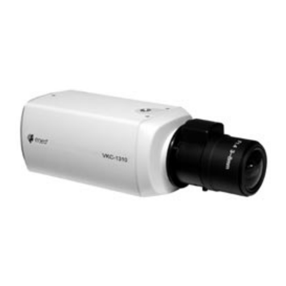
- Seite 1 Montage und Betriebsanleitung Farb-Kameras VKC-1310S und VKC-1311S Installation and Operating Instructions Colour Camera VKC-1310S and VKC-1311S Mode d’emploi Caméra Couleur VKC-1310S et VKC-1311S Instrucciones de manejo Camára Color VKC-1310S y VKC-1311S...
-
Seite 2: Inhaltsverzeichnis
Inhaltsverzeichnis Sicherheitshinweise............................4 Allgemeine Beschreibung........................... 4 Anschluss und Bedienung..........................6 3.1 Anschlussbeispiel bei Verwendung mehrerer Kameras..................7 Einstellung................................. 8 4.1 Einstellung der DIP-Schalter..........................8 Steckerbelegung.............................. 10 Objektivmontage und –anpassung ........................11 Einstellungen bei Objektiven ..........................12 Technische Daten ............................14 Maßzeichnungen ............................. - Seite 3 Sommaire Consignes de sécurité............................25 Description générale ............................25 Branchement et utilisation ..........................27 3.1 Exemple de branchement en cas d’utilisation de plusieurs caméras..............28 Réglage ................................29 4.1 Réglage des commutateurs DIP ........................29 Affectation des broches du connecteur ......................31 Montage et adaptation de l’objectif ........................
-
Seite 4: Sicherheitshinweise
• Zur Reinigung der Gerätegehäuse immer nur ein mildes Haushaltsmittel verwenden. Niemals Verdünner oder Benzin benutzen, dies kann die Oberfläche dauerhaft schädigen. 2. Allgemeine Beschreibung • 1/3” Interline Transfer CCD, VKC-1310S Standardauflösung (330 TV-Linien) • 1/3” Interline Transfer CCD, VKC-1311S hochauflösend (480 TV-Linien) • Gegenlichtkompensation (BLC) •... -
Seite 5: Lieferumfang
Lieferumfang • Kamera VKC-1310S oder VKC-1311S mit CS-Mount-Anschluss • 4-pol. Y/C-Stecker für Videosignal oder DC-Spannungsgesteuerte Objektive • C/CS-Mount-Ring • Staubschutzdeckel • Betriebsanleitung... -
Seite 6: Anschluss Und Bedienung
3. Anschluss und Bedienung Rückansicht 12VDC/24VAC 230VAC Seitenansicht D P B LED-Anzeige B leuchtet bei eingeschalteter Kamera grün auf. Spannungseingang / 12VDC/24VAC-Spannungseingang. Netzgerät siehe „Technische Daten”. 230VAC-Spannungsversorgung über Netzkabel C. Netzkabel Zuerst Anschlüsse herstellen, dann Geräte einschalten. LEVEL Signalpegel zur Einstellung des Ausgangspegels über Potentiometer D für DC-Spannungsgesteuerte Objektive. -
Seite 7: Anschlussbeispiel Bei Verwendung Mehrerer Kameras
3.1 Anschlussbeispiel bei Verwendung mehrerer Kameras Umschalteinheit VIDEO OUT-Buchse VIDEO IN-Buchse VIDEO IN-Buchse VIDEO OUT-Buchse Netzanschluss VIDEO OUT-Buchse VIDEO IN-Buchse Netzanschluss Monitor PHASE Hinweis Bedienungsanleitung der zu verwendenden Geräte und Komponenten sorgfältig lesen. Geräte und Komponenten erst nach Herstellung aller Anschlüsse einschalten. PHASE-Einstellung Am Potentiometer P der Kamera 1 so lange drehen, bis der Bildaustastimpuls mit dem der Kamera 2 zeitlich übereinstimmt. -
Seite 8: Einstellungen
4. Einstellungen 4.1 Einstellung der DIP-Schalter SW10 Schalter- aes / off / on / on / dc / AGC-N / off / on / mes / on / off / off / video / off / on / off / kennzeichnung on / int off / L/L... - Seite 9 Schalter- aes / off / on / on / dc / AGC-N / off / on / mes / on / off / off / video / off / on / off / kennzeichnung on / int off / L/L dc: Verwendung von DC-Spannungsge- video: Verwendung von videosignalge- Auto Iris...
-
Seite 10: Steckerbelegung
5. Steckerbelegung Spannungsversorgungs-Anschluss 12VDC 24VAC Hinweis Spannungsversorgung erst herstellen, wenn alle anderen Anschlüsse vorgenommen sind. Es wird die Verwendung von Netzgeräten mit stabilisierter Ausgangsspannung (12VDC ± 10%) empfohlen. DC-Spannungsgesteuerte Objektive Bezeichnung Dämpfung (-) Dämpfung (+) Antrieb (+) Antrieb (-) Objektiv-Anschluss E/I-Schalter in off-Position A/I-Schalter in dc-Position Signalhöhe... -
Seite 11: Objektivmontage Und -Anpassung
6. Objektivmontage und -anpassung Objektivmontage Vor dem Aufschrauben des Objektives Deckel N abnehmen. Staubschutzdeckel Objektiv Objektiv einschrauben und bei Objektiven mit automatischer Blende das Objektivkabel in die Buchse „LENS” stecken. Bei Verwendung eines C-Mount-Objektives den C-Mount-Ring K einschrauben. C/CS-Mount Anpassung LEVEL Hinweis Für die Video-Pegeleinstellung wird empfohlen, die Funktionen Shutter (SW 1) -
Seite 12: Einstellungen Bei Objektiven
7. Einstellungen bei Objektiven C-Mount Objektiv CS-Mount Objektiv Auflagemaßein- Diese Einstellung (Abstand zwischen Objektivfassung und Sensorfläche) muss durch- stellung bei Objektiven geführt werden, wenn mit dem Objektiv-Schärfering keine einwandfreie Scharfstellung mit fester Brennweite erzielt werden kann, bzw. um die ∞ - Position zu justieren. Bei der Scharfstellung die Kamera auf eine Vorlage richten, deren Entfernung mindes- tens die 2000-fache Brennweite ab Linsenvorderseite beträgt. - Seite 13 Begriffserklärung zur Blendeneinstellung AGC, Automatische Diese setzt ein, wenn die Beleuchtungsstärke nicht mehr ausreicht, um ein volles Verstärkungsregelung Videosignal (1Vss) zu liefern. Je größer die Verstärkung, desto mehr Rauschen kommt (automatic gain ins Bild. Der Einsatzpunkt liegt meistens zwischen 0,8 und 1,0 Vss. control) Weißclip Begrenzung des Signals bei hohen Bildamplituden.
-
Seite 14: Technische Daten
8. Technische Daten Modell VKC-1310S VKC-1311S EDV-Nr. 91934 91951 91935 91952 Aufnahmesensor 1/3" Interline Transfer CCD System CCIR/PAL Signalverarbeitung Digital (DSP) Synchronisation Netzverkoppelt / Intern Netzverkoppelt / Intern Empfindlichkeit 0,45Lux bei F1,2 1,3Lux bei F1,2 bei 50% Videosignal gemessen Horizontale Auflösung... -
Seite 15: Safety Instructions
• Use only a mild detergent to clean the housing. Never use dilution or gasoline for this can cause permanent damage to the surface. 2. General Description • 1/3” Interline Transfer CCD, VKC-1310S standard resolution (330 TV lines) • 1/3” Interline Transfer CCD, VKC-1311S high resolution (480 TV lines) • Backlight compensation (BLC) •... -
Seite 16: Connection And Operating
3. Connection and Operation Rear view 12VDC/24VAC 230VAC Side view D P B LED-indicator B lights green when the camera is switched on. Power supply / 12VDC/24VAC power supply. Power supply unit see „Specifications”. 230VAC power supply via power cord C. Make the connections first, then switch power cord the unit on. -
Seite 17: Sample Connections For The Use Of Multiple Cameras
3.1 Sample connections for the use of multiple cameras Switch over unit VIDEO OUT jack VIDEO IN jack VIDEO IN jack VIDEO OUT jack Power supply VIDEO OUT jack VIDEO IN jack Power supply Monitor PHASE Note Read the operation manual first. Power up unit and other components only after all connections are made. -
Seite 18: Settings
4. Settings 4.1 DIP switch settings SW10 Label aes / off / on / on / dc / AGC-N / off / on / mes / on / off / off / video / off / on / off / on / int off / L/L aes: The automatic shutter control (AES) - Seite 19 Label aes / off / on / on / dc / AGC-N / off / on / mes / on / off / off / video / off / on / off / on / int off / L/L off: AGC off on: Constant video signal level at low light Automatic or changing light conditions...
-
Seite 20: Pinout
5. Pinout Power Supply 12VDC 24VAC Note Only switch on the power supply when all the other connections have been carried out. The use of power supply units with stabilised output voltage (12VDC ±10%) is recommended.len. DC voltage controlled lenses Description Damping (-) Damping (+) -
Seite 21: Lens Mounting And Adjustment
6. Lens mounting and adjustment Lens mounting Remove dust cover N before screwing on the lens. Dust protection cap Lens Screw in the lens / with lenses with automatic diaphragm, plug the lens cable into the „LENS” socket. When using a C mount lens, screw on the C mount ring K. C/CS mount Adjustment LEVEL... -
Seite 22: Adjustment Of Lenses
7. Adjustment of lenses C mount lens CS mount lens Adjustment This adjustment (distance between lens casing and sensor surface) is required if a sharp of flange focus definition cannot be obtained with the lens focussing, or in order to adjust the ∞ position. for fixed focus lenses To obtain a sharp definition, point the camera at an object which is at least 2000 times further away from the front of the lens than the focal length. - Seite 23 Explanation of terms for iris setting AGC (automatic This starts tooperate when the light intensity is insufficient to deliver a full video signal gain control) (1Vp-p). The greater the gain, the greater the signal noise in the picture. It is generally activated between 0.8 and 1.0Vp-p.
-
Seite 24: Specifications
8. Specifications Model VKC-1310S VKC-1311S Part No. 91934 91951 91935 91952 Pickup Sensor 1/3" Interline Transfer CCD TV-System CCIR/PAL Signal Processing Digital (DSP) Synchronization Line Lock / Internal Line Lock / Internal Sensitivity for 50% Video Level 0.45Lux at F1.2 1.3Lux at F1.2... -
Seite 25: Consignes De Sécurité
2. Description générale • transfert interligne (Interline Transfer) 1/3" CCD, VKC-1310S résolution standard (330 lignes TV) • transfert interligne (Interline Transfer) 1/3" CCD, VKC-1311S haute résolution (480 lignes TV) • compensation du contre-jour (BLC) •... -
Seite 26: Etendue De La Livraison
Etendue de la livraison • caméra VKC-1310S ou VKC-1311S avec connexion monture CS • fiche mini-DIN, 4 pôles, Y/C pour des objectifs à commande par signal vidéo ou par tension DC • bague monture C/CS • couvercle de protection contre la poussière... -
Seite 27: Branchement Et Utilisation
3. Branchement et utilisation Vue arrière 12VDC/24VAC 230VAC Vue latérale D P B La DEL B s’allume en vert lorsque la caméra est en marche. Entrée de tension / Alimentation de tension 12VDC/24VAC. Bloc d’alimentation voir „caractéristiques techniques”. Alimentation de tension 230VAC par le câble secteur C. câble secteur Effectuez d’abord le branchement, puis mettez les appareils en marche. -
Seite 28: Exemple De Branchement En Cas D'utilisation De Plusieurs Caméras
3.1 Exemple de branchement en cas d’utilisation de plusieurs caméras Unité de commutation Douille VIDEO OUT Douille VIDEO IN Douille VIDEO IN Douille VIDEO OUT Tension Douille VIDEO OUT Douille VIDEO IN Tension Moniteur PHASE Remarque Lisez soigneusement la notice des appareils et composants à utiliser. Mettez les appareils et les composants uniquement en marche après avoir effectué... -
Seite 29: Réglage
4. Réglages 4.1 Réglage des commutateurs DIP SW10 Identification aes / off / on / on / dc / AGC-N / off / on / mes / on / off / off / video / off / on / off / commutateur on / int off / L/L... - Seite 30 Identification aes / off / on / on / dc / AGC-N / off / on / mes / on / off / off / video / off / on / off / commutateur on / int off / L/L on: Pour des objectifs à...
-
Seite 31: Affectation Des Broches Du Connecteur
5. Affectation des broches du connecteur Tension d’alimentation 12VDC 24VAC Remarque Etablir l’alimentation de tension seulement après la réalisation de tous les autres branchements. L’utilisation de blocs d’alimentation à tension de sortie stabilisée (12VDC ±10%) est recommandée. Objectifs à commande par tension DC Désignation affaiblissement (-) affaiblissement (+) -
Seite 32: Montage Et Adaptation De L'objectif
6. Montage et adaptation de l’objectif Montage de l’objectif Retirer le couvercle N avant de visser l’objectif. Couvercle de protection contre la poussière Objectif Vissez l’objectif et, pour les objectifs avec diaphragme automatique, brancher le câble d’objectif dans la prise „LENS”. Montage avec C/CS Lors de l’utilisation d’un objectif monture C, visser la bague K du monture C. -
Seite 33: Réglages Sur Objectifs
7. Réglages sur objectifs Objectif monture C Objectif monture CS Réglage Ce réglage (écart entre la monture d’objectif et le plan du détecteur) doit être effectué du côte d’appui sur s’il n’est pas possible d’atteindre une mise au point parfaite avec l’anneau de mise objectifs à... - Seite 34 Explication des termes concernant le réglage du diaphragme AGC, Réglage Celui-ci se déclenche, si l’intensité lumineuse n’est plus suffisante pour fournir un automatique du gain Celui-ci se déclenche, si l’intensité lumineuse n’est plus suffisante pour fournir un (automatic gain signal vidéo complet (1Vss). Plus le gain est grand, plus le bruit est important sur control) l’image.
-
Seite 35: Caractéristiques Techniques
8. Caractéristiques techniques Modèle VKC-1310S VKC-1311S N° informatique 91934 91951 91935 91952 Capteur de prise de vue Interline Transfer 1/3" CCD Système CCIR/PAL Traitement des signaux Numérique (DSP) Synchronisation Couplée au secteur / Interne Couplée au secteur / Interne Sensibilité mesurée 0,45Lux à... -
Seite 36: Instrucciones De Seguridad
• Utilice siempre un producto suave para limpiar la carcasa de la cámara. No emplee jamás un disolvente o gasolina que pudiera dañar permanentemente la superficie. 2. Descripción general • Interline Transfer 1/3” CCD, VKC-1310S resolución estándar (330 líneas TV) • Interline Transfer 1/3” CCD, VKC-1311S alta resolución (480 líneas TV) • Compensación de contraluz (BLC) •... -
Seite 37: Contenido Del Paquete
Contenido del paquete • Cámara VKC-1310S ó VKC-1311S con conexión montura CS • Enchufe mini-DIN, Y/C, 4 polos para objetivos controlados por señal de vídeo o tensión DC • Anillo montura C/CS • Tapa protectora contra el polvo • Manual de instrucciones... -
Seite 38: Conexión Y Manejo
3. Conexión y manejo Vista trasera 12VDC/24 VAC 230VAC Vista lateral D P B El LED B se ilumina en verde cuando la cámara está encendida. Entrada de tensión / Alimentación de corriente de 12VDC/24VAC. 12VDC Bloque de alimentación véase cable de la red „Características técnicas”. -
Seite 39: Ejemplo De Conexión Utilizando Varias Cámaras
3.1 Ejemplo de conexión utilizando varias cámaras Unidad de conmutación Casquillo VÍDEO OUT Casquillo VÍDEO IN Casquillo VÍDEO IN Casquillo VÍDEO OUT Tensión Casquillo VÍDEO OUT Casquillo VÍDEO IN Tensión Monitor PHASE Nota Lea cuidadosamente el manual de instrucciones de todos los aparatos y componentes que vaya a utilizar. -
Seite 40: Ajustes
4. Ajustes 4.1 Ajuste de los conmutadores DIP SW10 Identificación aes / off / on / on / dc / AGC-N / off / on / mes / on / off / off / video / off / on / off / del conmutador on / int off / L/L... - Seite 41 Identificación aes / off / on / on / dc / AGC-N / off / on / mes / on / off / off / video / off / on / off / del conmutador on / int off / L/L on: Para objetivos con control de diafragma off: EI desactivada con objetivos controlados Modo...
-
Seite 42: Asignación De Los Contactos
5. Asignación de los contactos Abastecimiento de tensión 12VDC 24VAC Nota No establecer la alimentación de tensión hasta que no se hayan efectuado todas las demás conexiones. Se recomienda utilizar fuentes de alimentación con tensión de salida estabilizada (12VDC ±10%). Objetivos controlados por tensión DC Descripción amortiguación (-) -
Seite 43: Montaje Y Ajuste Del Objetivo
6. Montaje y ajuste del objetivo Montaje del objetivo Antes de enroscar el objetivo se debe retirar la tapa N Tapa de protección contra el polvo Objetivo Enroscar el objetivo y, en el caso de objetivos con diafragma automático, introducir el cable del objetivo en el casquillo „LENS“. -
Seite 44: Ajustes En Objetivos
7. Ajustes en objetivos Objetivo montura C Objetivo montura CS Ajuste de la medida Este ajuste (distancia entre la montura del objetivo y la superficie sensora) se debe de asiento en objetivos realizar cuando con el anillo de nitidez del objetivo no se puede conseguir un enfoque con distancia focal fija perfecto, o bien para ajustar la posición ∞... - Seite 45 Explicación de conceptos para el ajuste del diafragma AGC, regulación auto- Empieza a actuar cuando la intensidad de iluminación ya no es suficiente para mática de ganancia proporcionar una señal de vídeo completa (1 Vss). Cuanto mayor es la ganancia, tanto (automatic gain más ruido entra en la imagen.
-
Seite 46: Características Técnicas
8. Características técnicas Modelo VKC-1310S VKC-1311S N° procesamiento de datos 91934 91951 91935 91952 Sensor de toma Interline Transfer 1/3" CCD Sistema CCIR/PAL Tratamiento de señales Numérico (DSP) Sincronización Acoplada a la red / Interna Acoplada a la red / Interna... -
Seite 47: Medidas
9. Maßzeichnung – Dimensional drawing – Croquis – Medidas 230VAC 12VDC/24VAC Maße - Dimensions - Medidas: mm... - Seite 48 ® ist eine eingetragene Marke der Videor Technical E. Hartig GmbH Vertrieb ausschließlich über den Fachhandel. ® eneo is a registered trademark of Videor Technical E. Hartig GmbH Exclusive distribution through specialised trade channels only. eneo ® est une marque propriété de Videor Technical E. Hartig GmbH Distribution et vente à...