Inhaltsverzeichnis
Werbung
Verfügbare Sprachen
Verfügbare Sprachen
Werbung
Kapitel
Inhaltsverzeichnis

Verwandte Anleitungen für Rohde & Schwarz HMP2020


Inhaltszusammenfassung für Rohde & Schwarz HMP2020
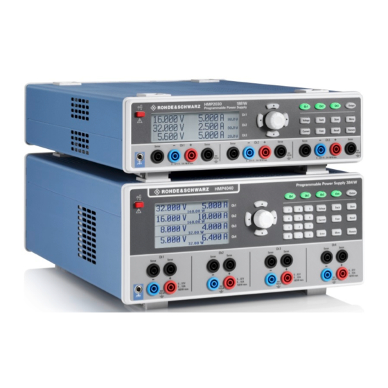
- Seite 1 ¸HMP Series Power supply Benutzerhandbuch User Manual *5800449202* 5800449202...
-
Seite 2: Allgemeine Hinweise Zur Ce-Kennzeichnung
Allgemeine Hinweise zur CE-Kennzeichnung ROHDE & SCHWARZ Messgeräte erfüllen die Bestim- mungen der EMV Richtlinie. Bei der Konformitätsprüfung werden von ROHDE & SCHWARZ die gültigen Fach- grund- bzw. Produktnormen zu Grunde gelegt. In Fällen, wo unterschiedliche Grenzwerte möglich sind, werden von ROHDE &... -
Seite 3: Inhaltsverzeichnis
Inhalt Inhalt Wichtige Hinweise ..... . 4 Symbole ........4 Auspacken . -
Seite 4: Wichtige Hinweise
Wichtige Hinweise 1 Wichtige Hin- kann. Ebenso kann die Wärmeentwicklung bei gleichzeiti- gem Betrieb aller Geräte dadurch zu groß werden. weise Transport und Lagerung Bewahren Sie bitte den Originalkarton für einen eventu- ellen späteren Transport auf. Transportschäden aufgrund einer mangelhaften Verpackung sind von der Gewährlei- Symbole stung ausgeschlossen. -
Seite 5: Bestimmungsgemäßer Betrieb
Wichtige Hinweise Vor jedem Einschalten des Produkts ist sicherzustellen, mischer Einwirkung betrieben werden. Die Betriebslage dass die am Produkt eingestellte Nennspannung und die ist beliebig, eine ausreichende Luftzirkulation ist jedoch zu Netznennspannung des Versorgungsnetzes übereinstim- gewährleisten. Bei Dauerbetrieb ist folglich eine horizontale men. -
Seite 6: Wartung
Quelle der Niederspannungsinstallation ist. Feinsicherung 5 x 20mm träge; 250V~ IEC 60127-2/5; EN 60127-2/5 ❙ Messkategorie IV: Messungen an der Quelle der Niederspannungsinstallation (z.B. an Zählern). ¸HMP2020 / ¸HMP2030: ❙ Messkategorie III: Messungen in der Netzspannung Sicherungsnennstrom Gebäudeinstallation (z.B. Verteiler, Leistungsschalter, fest... -
Seite 7: Batterien Und Akkumulatoren/Zellen
Wichtige Hinweise ¸HMP4030 / ¸HMP4040: 1.14 Produktentsorgung Netzspannung Sicherungsnennstrom 115V 2 x 10A 230V 2 x 5A Abb. 1.4: Produktkennzeichnung nach EN 1.13 Batterien und Akkumulatoren/Zellen 50419 Werden die Hinweise zu Batterien und Akkumulatoren/Zellen Das ElektroG setzt die folgenden EG-Richtlinien um: nicht oder unzureichend beachtet, kann dies Explosion, Brand ❙... -
Seite 8: Bezeichnung Der Bedienelemente
SENSE (4mm Sicherheitsbuchsen; 2 x pro Kanal) Bedienelemente Kompensation der Zuleitungswiderstände CH1 (4mm Sicherheitsbuchsen) Ausgänge Kanal 1; 0...32 V / 5 A (HMP2020 0...32 V / 10 A) CH2 (4mm Sicherheitsbuchsen) Gerätefrontseite ¸HMP2030 Ausgänge Kanal 2; 0...32 V / 5 A (beim ¸HMP2020 entfällt Kanal 3) -
Seite 9: Abb. 2.3: Gerätevorderseite ¸Hmp4040
Bezeichnung der Bedienelemente Abb. 2.3: Gerätevorderseite ¸HMP4040 Drehgeber CH1 (4mm Sicherheitsbuchsen) Drehknopf zum Einstellen und Bestätigen der Sollwerte Ausgänge Kanal 1; 0...32 V / 10 A Numerische Tastatur (Tasten) SENSE (4mm Sicherheitsbuchsen; 2 x pro Kanal) Einstellen der Sollwerte Kompensation der Zuleitungswiderstände CH1 (Taste beleuchtet) CH2 (4mm Sicherheitsbuchsen) Wahltaste Kanal 1... -
Seite 10: Kurzbeschreibung ¸Hmp Serie
5 A und bei 32 V immer noch mit 2,5 A belastet werden zelnen, logisch verknüpfbaren elektronische Sicherungen können. Wie das ¸HMP2030 liefert das ¸HMP2020 (FuseLink), die gemäß Anwendervorgabe im Fehlerfall die eine Leistung von 188 W, jedoch steht hier neben dem verknüpften Kanäle (z.B. -
Seite 11: Bedienung Der ¸Hmp Serie
Netzgerät in der gleichen Betriebsart wie vor dem letzten Einstellbare Maximalwerte Ausschalten. Alle Geräteeinstellungen (Sollwerte) werden Beim ¸HMP2020 stellen CH1 und ¸HMP2020: in einem nichtflüchtigen Speicher abgelegt und beim Wie- CH2 durchgehend 0 V bis 32 V bereit, wobei der Ausgangs- dereinschalten abgerufen. -
Seite 12: Einstellen Der Strombegrenzung
160 W pro Kanal (384 W max.) 160 W pro Kanal (384 W max.) ¸HMP4040: soll Z.B. ergibt sich beim ¸HMP2020 bei 160 W pro Ka- nal für 24 V Spannung ein maximaler Strom von 6,67 A Spannungsregelung Stromregelung bzw.3,33 A beim ¸HMP2030. -
Seite 13: Erweiterte Bedienfunktionen
Erweiterte Bedienfunktionen 5 Erweiterte den betreffenden Ausgang deaktivieren, danach die Last verbinden und erst danach den Ausgang aktivieren. Beim Aktivieren des Ausgangs wird so ein optimales Ein- Bedienfunktionen schwingverhalten realisiert. Hochempfindliche Halbleiter, wie z.B. Laserdioden, bitte nach Maßgabe des Herstellers betreiben. -
Seite 14: Überspannungsschutz (Ovp)
Erweiterte Bedienfunktionen triebsart MEASURED gilt der vom Gerät zurück gemessene Wert als Schaltschwelle für den Überspannungsschutz. In der Betriebsart PROTECTED gilt der am Gerät eingestellte Wert als Schaltschwelle für den Überspannungsschutz. Mit der linken Pfeiltaste kann eine Menüebene zurückge- Abb. 5.2: sprungen werden. -
Seite 15: Beispiel Für Eine Arbitrarykurve (¸Hmp2030)
EasyArb-Softwaremodul der HMExplorer Software. Hier kann Punkt für Punkt mit dem Editor eine Kurve er- 5.3.6 Key Brightness (nur ¸HMP2020/2030) stellt werden. Einzelne Punkte können mit der Funktion „+“ Durch Druck auf den Drehgeber wir das Menü KEy oder „–“... -
Seite 16: Display Contrast
Erweiterte Bedienfunktionen 5.3.13 Reset Device Durch Druck auf den Drehgeber wir das Menü RESET DEVICE aufgerufen. Dieser Menüpunkt setzt das Gerät in Abb. 5.8: Key seinen Ursprungszustand (Werkseinstellung) zurück. Alle Fallback Time vorgenommenen Geräteeinstellungen werden gelöscht. (¸HMP2030) 5.3.8 Display Contrast Durch Druck auf den Drehgeber wir das Menü... -
Seite 17: Remote Betrieb
Remote Betrieb 6 Remote Betrieb Die RS-232 Schnittstelle ist als 9polige D-SUB Buchse ausgeführt. Über diese bidirektionale Schnittstelle können Einstellparameter, Daten und Bildschirmausdrucke von einem externen Gerät (z.B. PC) zum Netzgerät gesendet Die ¸HMP Serie ist standardmäßig mit einer HO720 bzw. -
Seite 18: Ethernet (Option Ho730/Ho732)
Remote Betrieb kann mit einem beliebigen Terminalprogramm über Internet austauschen. SCPI-Kommandos mit der ¸HMP Serie kommuniziert werden. Damit Netzelemente mit einer privaten IP-Adresse über das Internet Daten austauschen können, müssen diese Zusätzlich kann die kostenlose Software HMExplorer über einen Router, der eine IP-Adressumsetzung durch- genutzt werden. -
Seite 19: Ethernet Einstellungen
Remote Betrieb Server (engl. DHCP; Dynamic Host Configuration Protocol) werden. In lokalen Netzwerken wird meistens die erste IP benötigt. Bei einem DHCP-Server kann ein IP-Adress- Adresse innerhalb eines Netzwerks für diesen (Gateway-) bereich für die automatische Zuteilung von IP-Adressen Router verwendet. Router die in einem lokalen Netzwerk eingestellt werden. -
Seite 20: Fortgeschrittene
Fortgeschrittene Anwendungsmöglichkeiten 7 Fortgeschrittene Wert eingestellt sein. Geht einer der Ausgänge in die Strom- begrenzung, bricht naturgmäß die Gesamtspannung ein. Nach Möglichkeit sollten die beiden Spannungen auf einen Anwendungs- ähnlichen Wert eingestellt werden, um die Belastungen zu verteilen (nicht unbedingt notwendig). Wenn ein (niederoh- möglichkeiten miger) Verbraucher angeschlossen ist, darf nie nur ein Kanal eingeschaltet sein. - Seite 21 Fortgeschrittene Anwendungsmöglichkeiten zur Verfügung gestellt. Welcher Kanal dabei den größeren Strom liefert ist nicht vorhersagbar, da auch Kanäle mit identische eingestellten Spannungswerten eine geringe Spannungsdifferenz aufweisen können. Durch eine leichte Spannungserhöhung kann die Lastverteilung beeinflusst werden. Wird bei einem Kanal die Spannung um z.B. 50mV höher gewählt (bei einem Satz identischer Kabel), wird zunächst der Strom von diesem Kanal geliefert.
-
Seite 22: Technische Daten
1,5 mV <250 µV Programmierbare Netzgeräte 2 / 3 / 4 Kanäle Strom: <1 mA HMP2020 HMP2030 HMP4030 HMP4040 Stabilisierung bei Laständerung (10…90 %): Spannung: <0,01 % + 2 mV Alle Angaben bei 23 °C nach einer Aufwärmzeit von 30 Minuten. -
Seite 23: Anhang
Geräterückseite ....10 Abb. 4.1: Einstellbare Maximalwerte ¸HMP2020 . . . 11 Abb. 4.2: Einstellbare Maximalwerte ¸HMP2030 . . . 11 Abb. - Seite 24 Anhang Display Contrast: 16 Sicherungstypen: 7 Display & Key Brightness: 16 Sicherungswechsel: 6 Dualschnittstelle: 15 Spannungsbereich: 10 Spannungsregelung: 12 EasyArb Funktion: 10 Start Waveform: 15 Edit Waveform: 14, 15 Stop Waveform: 15 Einschalten: 11, 12 Strombegrenzung: 12, 13, 14, 18, 19 Elektronische Sicherung: 12, 13 Stützpunkte: 15 Fuse Delay: 14...
- Seite 25 Anhang...
-
Seite 26: General Information Regarding The Ce Marking
General remarks regarding the CE marking General Information Regarding the CE Marking ROHDE & SCHWARZ measuring instruments comply with regulations of the EMC Directive. ROHDE & SCHWARZ is basing the conformity assessment on prevailing generic and product standards. In cases with potentially different thresholds, ROHDE &... - Seite 27 Content Content Important Notes ..... . . 28 Symbols ........28 Unpacking .
-
Seite 28: Important Notes
Important Notes 1 Important Notes Transport and Storage Please keep the original packaging for possible shipping at a later point. Damage during transport due to inappropriate packaging is excluded from the warranty. The instrument Symbols must be stored in dry, closed indoor premises. If the in- strument was transported under extreme temperatures, it is advisable to allow a minimum of two hours to reach the appropriate temperature before operating the instrument. -
Seite 29: Intended Operation
Important Notes Intended Operation Cooling The measuring instrument is intended only for use by The heat produced inside the power supply is guided personnel familiar with the potential risks of measuring to the exterior via temperature-controlled fan. This fan, electrical quantities. For safety reasons, the measuring combined with a cooling element, is located in a "cooling instrument may only be connected to properly installed duct"... -
Seite 30: Measurement Categories
❙ Measurement CAT IV: Measurements at the source of IEC 60127-2/5; EN 60127-2/5 the low voltage installations (e.g. meters) ❙ Measurement CAT III: Measurements in building R&S®HMP2020 / R&S®HMP2030: installations (e.g. power distribution installations, power Mains voltage Fuse nominal current... -
Seite 31: Product Disposal
Important Notes can be short-circuited by other conductive materials. Cells and batteries must not be removed from their original packaging until they are ready to be used. 4. Keep cells and batteries out of reach of children. Seek medical assistance immediately if a cell or battery was swallowed. -
Seite 32: Description Of The Operating Elements
Loading stored measuring instrument configurations STORE (key illuminated) Storing measuring instrument configurations Fig. 2.2: Rear panel of R&S®HMP2030 CH3 (key illuminated) Option key channel 3 (not available for the HMP2020) REMOTE / LOCAL (key illuminated) Switching between keypad and external control MENU (key illuminated) Accessing the menu options Fig. -
Seite 33: Fig. 2.3: Front Panel Of R&S®Hmp4040
Description of the Operating Elements Fig. 2.3: Front panel of R&S®HMP4040 CH1 (4mm safety sockets): Front Panel of R&S®HMP4040 Outputs channel 1; 0...32 V / 10 A (for the R&S®HMP4030, channel 4 is omitted) SENSE (4mm safety sockets; 2 x per channel): POWER (key): Power switch to switch the instrument Compensating the line resistances on and off... -
Seite 34: Brief Description
32 V channel available to benefit the double output power of up to 10 A. The R&S®HMP4030 includes R&S®HMP2020 and R&S®HMP2030 include a 2-line and three identical channels with a continuous voltage range of 3-line LCD display (240 x 64 pixel. R&S®HMP4030 and 0 to 32 V that at up to 16 V can be charged with 10 A and at R&S®HMP4040 include a 3-line and 4-line LCD display... -
Seite 35: Operating The R&S®Hmp Series
Adjustable Maximum Values When switching the instrument on, the R&S®HMP power R&S®HMP2020: For the R&S®HMP2020, CH1 and CH2 will use the same operating mode that was in use at the continuously provide 0 V to 32 V, where the output power time the unit was last switched off. -
Seite 36: Setting The Current Limit
The intent is to prevent damage to the experimen- tal circuit in case an error occurs (e.g. a short circuit). For instance, for the R&S®HMP2020 at 160 W per channel for a 24 V voltage, this would result in a maximum current of 6.67 A, and .3.33 A for the R&S®HMP2030. -
Seite 37: Advanced Operating Functions
Operating the R&S®HMP Series 5 Advanced Ope- If the current for a channel exceeds the value Imax and if the electronic fuse for this channel has been activated via FUSE key (see Setting the Current Limit), all channels rating Functions interlinked with this channel will be switched off. -
Seite 38: Example Of An Arbitrary Signal (R&S®Hmp2030)
Advanced Operating Functions 5.3.4 Arbitrary the arbitrary function. Pressing the OUTPUT key deacti- Activate the menu ARBITRARy by pressing the knob. The vates only the respective channel and does not stop the HMP series allows you to generate freely programmable function. -
Seite 39: Fig. 5.8: Key Fallback Time (R&S®Hmp2030)
Use the left arrow key to return to the previous 5.3.6 Key Brightness (only R&S®HMP2020/2030) menu level. Activate the menu KEy BRIGHTNESS by pressing the If all the channels do not have the same firmware, a firmware knob. -
Seite 40: Remote Control
Advanced Operating Functions 6 Remote Control By default, the R&S®HMP series includes a HO720 USB/ RS-232 interface. You can find the drivers for this interface on the product CD enclosed with the power supply or on the ROHDE & SCHWARZ Homepage. The LED for the remote key is illuminated in white (= Tx Data (data from power supply to external device) active), if communication to the instrument has been... -
Seite 41: Ip Networks (Ip - Internet Protocol)
Remote Control 6.3.1 IP networks (IP – Internet protocol) Apart from the organization of IP addresses into public and In order that two or several network elements (e.g. measu- private address ranges, IP addresses are also divided into ring instruments, host/PC‘s, …) can communicate over a classes (Class: A, B, C, D, E). -
Seite 42: Ethernet Settings
Remote Control one logical AND operation between IP address and subnet In general, the HO730 works with a RAW-Socket communication mask. The result is the network quota of the IP address. to control the instrument and to retrieve the measuring values. The host quota of the IP address takes place via the bit by Therefore, a TMC protocol or a similar protocol will not be used. -
Seite 43: Advanced Applications
Advanced Applications 7 Advanced Appli- should be set to the identical value. If one of the outputs exceeds the current limit, the total voltage will naturally collapse. It is advisable to set both voltages to a similar cations value to distribute the loads evenly (not absolutely neces- sary). -
Seite 44: Specifications
1,5 mV Voltage: Programmable power supplies 2 / 3 / 4 channels <250 µV HO740 HMP2020 HMP2030 HMP4030 HMP4040 Current <1 mA HZ10S All data valid at 23°C after 30 minute warm-up. Residual deviation after a load change (10 to 90 %):... -
Seite 45: Appendix
....34 HZ42 2RU 19“ rackmount kit Fig. 4.1: Adjustable maximum values R&S®HMP2020 . .35 HZ72 GPIB-cable 2 m Fig. 4.2: Adjustable maximum values R&S®HMP2030 . .35 HZP91 19“... - Seite 46 Appendix Display Contrast: 36 Total current: 39 Display & Key Brightness: 36 Tracking function: 34 Driver: 37 Tracking mode: 34 Dual Interface: 36 Transfer Waveform: 35 Transport: 26 EasyArb function: 31 Edit Waveform: 35 USB interface: 38 Electronic fuse: 33, 34 Virtual COM Port: 38 Fuse Delay: 34 VOLTAGE: 29, 30, 32, 33, 34...
- Seite 47 Appendix...
- Seite 48 © 2015 Rohde & Schwarz GmbH & Co. KG Mühldorfstr. 15, 81671 München, Germany Phone: +49 89 41 29 - 0 Fax: +49 89 41 29 12 164 E-mail: info@rohde-schwarz.com Internet: www.rohde-schwarz.com Customer Support: www.customersupport.rohde-schwarz.com Service: www.service.rohde-schwarz.com Subject to change – Data without tolerance limits is not binding. R&S is a registered trademark of Rohde &...