Werbung
Verfügbare Sprachen
Verfügbare Sprachen
Quicklinks
Figure 1a: EM201E-240 Surface Mount Output
Module with 240V Relay Contacts
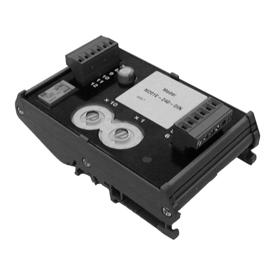
Figure 1b: EM201E-240-DIN Din Rail Mounted
Output Module with 240V Relay Contacts.
TO MOUNT, LOCATE LUG OVER TOP
OF RAIL AND ROTATE THE MODULE
DOWN TO CLIP INTO PLACE.
TO REMOVE, PUSH UPWARDS, AND
ROTATE TOP OF MODULE AWAY
FROM RAIL.
Figure 2: Module Wiring
NOTE: Wiring is the same for EM201E-240 and EM201E-240-DIN
Relay 1, N/O
7
Relay 2, N/C
8
Ground
9
Ground
10
Relay 2, N/C
11
Relay 1, N/O
12
8 9
6 7
5
4
3
2
1
0
TENS
ROTARY DECADE ADDRESS SWITCHES
Notes:
1. If short circuit isolation is not required, then the loop output should
be wired to terminal 5 rather than terminal 2. Terminal 5 is internally
connected directly to terminal 4.
2. In order to meet the requirements of European Safety Standards,
ensure that all cables carrying voltages in excess of 48V are suitably
fused.
EM201E-240:
0786
EM201E-240-DIN:
19
EN54-17: 2005, EN54-18: 2005
E200-93-01
EM201E-240
INSTALLATION INSTRUCTIONS FOR MAINS
SWITCHING OUTPUT MODULES
LOOP CABLE SCREEN TERMINAL
Loop -, Out
1
Loop +, Out - See Note 1
2
Loop -, In
3
Loop +, In
4
Loop +, Out - See Note 1
5
T6 - Not Connected
6
8 9
6 7
10
11
5
4
12
3
13
2
14
1
15
0
UNITS
Schneider Electric
DOP-IOD058
Fire and Security Oy
DOP-IOD060
Sokerilinnantie 11 C
02600 Espoo, Finland
Schneider Electric Fire & Security Oy, Sokerilinnantie 11 C, 02600 Espoo, Finland
EM201E-240-DIN
AND
This manual is intended as a quick reference installation guide. Please
refer to the control panel manufacturers installation manual for detailed
system information
GENERAL INFORMATION
The EM200+ series of modules are a family of microprocessor controlled
interface devices permitting the monitoring and/or control of auxiliary
devices. The EM201E-240 and EM201E-240-DIN are output modules,
providing 250VAC 5A rated voltage free contacts, both normally open
and normally closed.
SPECIFICATIONS
Operating Voltage Range:
Maximum Standby Current (µA): 275µA - No Communication
Fault Current:
Coil Activation/Deactivation Current: 76mA Maximum for 12mS
Relay Contact Rating:
Maximum rated continuous current with the switch closed (I
Maximum rated switching current (under short circuit) (I
Maximum leakage current (I
Maximum series impedance with the switch closed (Z
Operating Temperature:
Humidity:
Dimensions EM201E-240:
Dimensions EM201E-240-DIN:
Weight EM201E-240:
Weight EM201E-240-DIN:
Maximum Wire Gauge
INSTALLATION
Note: These modules must only be connected to control panels using
compatible proprietary analogue addressable communication
protocols for monitoring and control.
Disconnect loop power before installing modules or sensors.
High voltages may be present on terminals 7 to 12.
EM201E-240
1. The EM201E-240 includes a custom low profile surface-mounting box
with several options for fixing centres. To access all fixing points, and
the rear cable entry knock out, the circuit board must be removed. It
is held in place by two screws through the circuit board. Ensure that
these screws are replaced when refitting the circuit board.
2. If rear cable entry is not required, the box has several cover drill
points permitting the entry of cables using suitable glands.
3. Wiring to the EM201E-240 is made via two 6 way terminal strips
on the module circuit board, capable of supporting conductors up to
1.5mm². See figure 2 for connections.
4. An earthing terminal is provided in the surface mount box for
connection of the loop cable screen, if used, to ensure continuity.
See figure 1a.
EM201E-240-DIN
1. EM201E-240-DIN mounts onto standard 35mm x 7.5mm "Top Hat"
DIN rail. It must be mounted in a suitable cabinet meeting the
applicable safety standards.
2. Wiring to the EM201E-240-DIN is via plug in type terminals capable
of supporting conductors up to 2.5mm². See figure 2 for connections.
Ensure that the correct terminals are used for the loop and
switched voltage as damage may result from incorrect usage.
For both modules, the address is selected by means of rotary decade
address switches (see figure 2), accessed at the front of the module. A
screwdriver should be used to rotate the wheels to select the desired
address. (Note: The number of addresses available will be dependent on
panel capability, check the panel documentation for information on this.)
Short Circuit Isolators
All EM200+ series modules are provided with short circuit monitoring and
isolators on the intelligent loop. If required the isolators may be wired
out of the loop to facilitate the use of the modules on high current loaded
loops, for example if sounders are used. To achieve this, the loop out
positive should be wired to terminal 5 rather than terminal 2.
E N G L I S H
I 56- 1773- 015
15 to 30VDC (Min 19.5VDC to ensure LED
operation)
445µA - Communication LED blink enabled - 5 secs
375µA - Read 16 sec. LED blink 8 sec
8.8mA (Yellow LED illuminated)
5A, at 30VDC, 5A at 250VAC
max): 1A
c
max): 1A
s
max) with the switch open (isolated state): 15mA
L
max): 130 m ohm at 15Vdc
c
-20°C to 60°C
5% to 95% Relative Humidity
134mm(H) x 139mm(W) x 40mm(D)
127mm(H) x 76mm(W) x 48mm(D) (Including terminals)
195g
140g
1.5mm² - EM201E-240, 2.5mm² - (-DIN)
CAUTION
WARNING
I56-1773-015
Werbung

Verwandte Anleitungen für ESMI EM201E-240

Inhaltszusammenfassung für ESMI EM201E-240
- Seite 1 2. If rear cable entry is not required, the box has several cover drill points permitting the entry of cables using suitable glands. 3. Wiring to the EM201E-240 is made via two 6 way terminal strips on the module circuit board, capable of supporting conductors up to Figure 2: Module Wiring 1.5mm². See figure 2 for connections.
- Seite 2 Umidità: Umidità relativa compresa tra il 5% e il 95% (in assenza di condensa) Dimensioni del modello EM201E-240: 134 mm (H) x 139 mm (L) x 40 mm (P) Dimensioni del modello -DIN:127 mm (H) x 76 mm (L) x 48 mm (P) (compresi i morsetti) Figura 1b: Modulo di uscita montato su binario Din Peso del modello EM201E-240: 195 gr.
- Seite 3 -20 °C a 60 °C Humedad: 5% a 95% de humedad relativa Dimensiones de EM201E-240: 134 mm (alto) x 139 mm (ancho) x 40 mm (fondo) Dimensiones de EM201E-240-DIN: 127 mm (alto) x 76 mm (ancho) x 48 mm (fondo) (incluyendo terminales)
- Seite 4 2. Wenn die Kabeleinführung von der Rückseite nicht erforderlich ist, können die vorgesehen Bohrlöcher der Abdeckung in Verbindung mit geeigneten Kabelmanschetten genutzt werden. 3. Die Verdrahtung des EM201E-240 erfolgt über die 6-poligen Anschlussleisten auf der Platine mit einem zulässigen Kabelquerschnitt von max. 1,5mm² (Anschluss siehe Abbildung 2).