Inhaltsverzeichnis
Werbung
Verfügbare Sprachen
Verfügbare Sprachen
Montage- und Bedienungsanleitung
Mounting and operating instructions
Instructions de montage et mode d'emploi
®
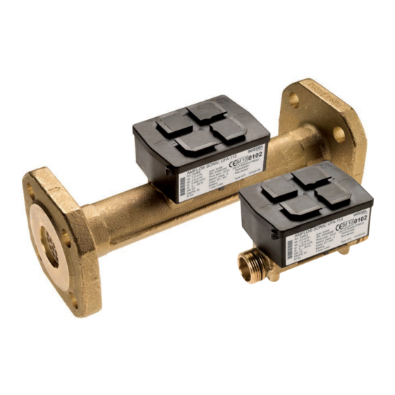
AMFLO
SONIC UFA-113
Ultraschall Durchflussgeber
Ultrasonic flow sensor
Débitmètre ultrasonique
Inhaltsverzeichnis
1
2
3
3.1
3.2
4
Table of contents
5
6
7
7.1
7.2
8
Sommaire
9
10
11
12
13
14
CE
6-255-IG-UM-EN-DE-FR-01
2
2
3
3
3
4
6
6
7
7
7
8
10
10
11
11
11
12
14
14
Werbung
Inhaltsverzeichnis

Verwandte Anleitungen für INTEGRA Metering AMFLO SONIC UFA-113

Inhaltszusammenfassung für INTEGRA Metering AMFLO SONIC UFA-113
-
Seite 1: Inhaltsverzeichnis
Montage- und Bedienungsanleitung Mounting and operating instructions Instructions de montage et mode d'emploi ® AMFLO SONIC UFA-113 Ultraschall Durchflussgeber Ultrasonic flow sensor Débitmètre ultrasonique Inhaltsverzeichnis Sicherheitshinweise Montage des Durchflussgebers Anschlüsse Spannungsversorgung Impulsausgang Technische Daten Table of contents Safety instructions Installation of flow sensor Connections Supply voltage Pulse output... -
Seite 2: Sicherheitshinweise
1 Sicherheitshinweise Diese Anleitung wendet sich an ausgebildetes Fachpersonal und enthält keine allgemeinen Arbeitsschritte. Wichtig! / Warnung! Die Plombierung am Durchflussgeber (Fig. A) darf nicht verletzt werden! Eine verletzte Plombierung hat das sofortige Erlöschen der Werksgarantie und der Eichung zur Folge. Das Impulskabel darf verlängert werden, aber die Gesamtlänge muss kleiner 10 m sein. -
Seite 3: Anschlüsse
3 Anschlüsse Das Anschlusskabel (Fig. D1) hat folgende Belegung: Farbe Batterie Fremdversorgung Weiss + Volumenimpuls Gelb Prüfimpuls / Kommunikation Blau Braun Nicht belegt + Spannungsversorgung Das Anschlusskabel vom Impulsmodul wird dazu an den Klemmen 10 (+) und 11 (-, GND) des Wärmerechen- werk angeschlossen. -
Seite 4: Technische Daten
4 Technische Daten Umgebungstemperatur: 5 ... 55 °C Mediumstemperatur: - Batterieversorgt: 90 °C - Fremdversorgt: 5 ... 130 °C / 150 °C qp ≥3.5 m3/h Es ist zu beachten, dass die Wassertemperatur über der Umgebungstemperatur liegen muss. Im Falle T ≤20 ºC oder Gefahr von Betauung ist die vergossene Zählervariante (Kälte/Klima) zu verwen- Wasser den. - Seite 5 ® AMFLO SONIC UFA-113...
-
Seite 6: Safety Instructions
5 Safety instructions This installation guide is intended for trained personnel and therefore does not include basic working steps. Important / Warnings The seal on the flow sensor (Fig. A) must not be damaged. A damaged seal will result in immediate invalidation of the factory warranty and calibration. -
Seite 7: Connections
7 Connections The connecting cable (Fig. D1) has the following assignment: colour Battery powered external supply white + volume pulse yellow Test pulse / communication blue brown not used + voltage supply The connecting cable of the pulse module is connected to the terminals 10 (+) and 11 (-, GND) of the heat cal- culator. -
Seite 8: Technical Data
8 Technical data Ambient temperature: 55 °C Medium temperature: Battery powered: 90 °C External powered: 5 ... 130 °C / 150 °C qp ≥3.5 m3/h Please notice that the water temperature must be higher than the ambient temperature. In case of T ≤20 ºC or danger of condensation, the sealed version should be used. - Seite 9 ® AMFLO SONIC UFA-113...
-
Seite 10: Consignes De Sécurité
9 Consignes de sécurité Ces instructions s’adressent à des employés qualifiés et ne contiennent pas d’indications d’ordre général. Attention! / Avertissement! Les scellés du débitmètre (Fig. A) ne doivent pas être brisés. Le bris des scellés annule automatiquement la garantie d’usine et l’étalonnage. Le câble d’impulsion peut être prolongé, mais la longueur totale ne doit pas dépasser 10 m. -
Seite 11: Connexions
11 Connexions L’attribution des câbles (Fig. D1) est la suivante : Couleur Pile Alimentation externe blanc + impulsion volumique jaune impulsion d’essai / communication bleu masse brun libre + alimentation électrique Le câble de raccordement du module d’impulsions est relié aux bornes 10 (+) et 11 (-, masse) du calculateur de chaleur. -
Seite 12: Données Techniques
12 Données techniques Température ambiante: 5 ... 55 °C Température du fluide: Alimentation à pile: 90 °C Alimentation externe: 5 ... 130 °C / 150 °C qp ≥3.5 m3/h Remarquez que la température de l’eau doit être supérieure à la température ambiante. Il faut utiliser la version étanche pour une température d’eau sous 20 °C ou en cas de condensation. - Seite 13 ® AMFLO SONIC UFA-113...
-
Seite 14: Anhang / Appendix / Appendice
13 Anhang / Appendix / Appendice Fig. A Platzierung der Plomben Placement of the seals Placement des scellés Fig. B Hinweispfeil für Durchflussrichtung Arrow indicating flow direction Flèche pour le sens d’écoulement du liquide Fig. C1 Fig. C2 ® AMFLO SONIC UFA-113... - Seite 15 Fig. D1 1: braun / brown / brun 2: gelb / yellow / jaune 3: weiss / white / blanc 4: blau / blue / bleu Fig. D2; Batterie / battery / pile 1: braun / brown / brun 2: gelb / yellow / jaune 3: weiss / white / blanc 4: blau / blue / bleu A: Prüfplus hochauflösend...
- Seite 16 info@integra-metering.com www.integra-metering.com...