Kessel 28 560 Anleitung Für Einbau, Bedienung Und Wartung
Minilift
Vorschau ausblenden
Andere Handbücher für 28 560:
- Anleitung für einbau, bedienung und wartung (24 Seiten)
Inhaltsverzeichnis
Werbung
Verfügbare Sprachen
Verfügbare Sprachen
Quicklinks
ANLEITUNG FÜR EINBAU, BEDIENUNG UND WARTUNG
KESSEL - Hebeanlage - Minilift
für fäkalienfreies Abwasser zur freien Aufstellung
Installation
Inbetriebnahme
der Anlage wurde durchgeführt von Ihrem Fachbetrieb:
Name/Unterschrift
Datum
Best. Nr. 28 560
Produktvorteile
Kompakte Bauweise
Förderhöhe bis 6,5 m
Einhand-Schnellverschluß
zur mobilen Verwendung der Pumpe
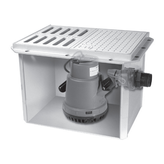
Abb. 28 560
Einweisung
Ort
Stempel Fachbetrieb
D Seite 1-12
GB Page 13-24
F Page 25-36
I
Pagina 37-48
NL Pagina 49-60
PL Strona 61-72
Änderungsstand: 2020/10
Sachnummer:
157-030
Techn. Änderungen vorbehalten
Werbung
Kapitel
Inhaltsverzeichnis

Verwandte Anleitungen für Kessel 28 560


Inhaltszusammenfassung für Kessel 28 560
- Seite 1 ANLEITUNG FÜR EINBAU, BEDIENUNG UND WARTUNG KESSEL - Hebeanlage - Minilift D Seite 1-12 GB Page 13-24 für fäkalienfreies Abwasser zur freien Aufstellung F Page 25-36 Pagina 37-48 NL Pagina 49-60 Best. Nr. 28 560 PL Strona 61-72 Produktvorteile Kompakte Bauweise Förderhöhe bis 6,5 m...
-
Seite 2: Inhaltsverzeichnis
Inhaltsverzeichnis 1. Allgemein Verwendung ..................Seite Anlagenbeschreibung ............... Seite 1.2.1 Überflurinstallation ................Seite 1.2.2 Unterflurinstallation ................Seite 2. Einsatzbereiche Dauerhafter Einbau ................Seite Mobiler Einsatz der Pumpe ............... Seite 3. Einbau Einbau in die Bodenplatte/Unterflurinstallation ........ Seite Freie Aufstellung/Überflurinstallation ..........Seite Hinweis ..................... -
Seite 3: Allgemein
Kanal-Anschlusshöhe anfallen. forderlich, wenn der Schlitzrost gegen eine Die Anlagenvariante Resistant ist überdies Abdeckplatte ausgetauscht wird. geeignet für eine Kombination aus Mit dem KESSEL-Aufsatzstück können Abwässern und salzhaltigen Medien sowie stufenlos beliebige Einbautiefen realisiert für Kondensat aus Brennwertgeräten. werden. -
Seite 4: Einsatzbereiche
- Vorsicht bei mobilem Einsatz: Eine Be- nutzung der Pum pe in Schwimmbecken und Gar tenteichen und de ren Schutz be rei- - Der KESSEL-Hebeanlage Minilift darf nur chen ist nur zu läs sig, wenn die Forderungen fäkalienfreies Abwasser zugeführt werden. -
Seite 5: Einbau
3. Einbau Einbau und Montage elektrischer Geräte dürfen nur durch eine Elektrofachkraft 5. Pumpe auf Führungsrippen am Grund erfolgen (Elektrofachkraft im Sinne VDE 0105) des Grundkörpers (1) setzen. Pumpe in 3.1 Einbau in die Bodenplatte/Unterflurinstallation der Füh rung zum Gewindestück schie- ben, da bei Anschlussstück (4) in den Gumminippel (9) einführen und mit Ver- schluß... - Seite 6 3. Einbau 9. Druckleitung aus PVC DN 40 (nach DIN 11 Grundkörper 8063) in Klebemuffe von Gewindestück (6) kleben und über Rückstauebene 12 Abdeckplatte mittels Rückstauschleife in nächstes 13 Pumpe Abwasserrohr führen. (Die Verbindung 14 Anschlussstück muss längs kraftschlüssig erfolgen) 15 Verschluss 10.
-
Seite 7: Freie Aufstellung/Überflurinstallation
3. Einbau 3.2 Freie Aufstellung/Überflurinstallation Bevor die Anlage aufgestellt wird, sind folgende Montagearbeiten zu erledi- gen: 1. Flachdichtung (8) über das Gewindeteil 2. Gumminippel (9) in das Gewindestück einstecken. 3. Komplettiertes Gewindestück von innen durch vorhandene Aussparung schie- ben. 4. Sechskantmutter (7) auf Pumpenan- schluss (6) schrauben. - Seite 8 3. Einbau 7. Druckleitung aus PVC DA 40 (nach DIN KESSEL- Zulaufstutzen (Bestellnr. 39005) Bitte beachten Sie: Die Schwimmer- 8063) in Klebemuffe von Pumpenan- oder der Rohrdurchführungsdichtung funk tion darf durch die Anbringung der seit- schluß (6) kleben und über Rückstau- (Best.
-
Seite 9: Ersatzteile
Ersatzteile Pos. Bezeichnung Art.Nr. Aktivkohlefilter mit Spannklammer 27208 Abdeckungsset mit Deckel, Kunststoffschrauben 28036 und Rändelmutter Deckeldichtung 680019 Austausch-Pumpe, 300 W 28836 Austauschset Flügelrad mit Ansaugdeckel 28039 Ansaugkorb 680013 Gumminippel 680020 Pumpenverriegelungsset 28031 Rückschlagklappe 27207 Verschlusshebel 680018 Kabeldichtung 680021 O-Ring 680014 Anschlussflansch 680017... -
Seite 10: Inbetriebnahme
4. Inbetriebnahme 4. Inbetriebnahme: Technische Daten: Die Anlage ist betriebsbereit, wenn die Laufraddurchgang: max.10 mm Elektroanschlussleitung mit dem Netzan- Temperatur: kurzfristig max. 75°C schluß verbunden ist. im Dauerbetrieb max. 50°C bei tiefster Schwimmereinstellung Für die Bedienung sind keine besonderen Leistungs- Vorkehrungen zu treffen, da die Anlage im Spannung Nennstrom... -
Seite 11: Inspektion Und Wartung
Inbetriebnahme, Inspektion/Wartung, Gewährleistung 4.2 Hinweis 5. Inspektion/Wartung - Die Installationen haben nach den gelten- den Normen und Vorschriften zu erfolgen. 5.1 Inspektion - örtliche Vorschriften und Verordnungen Die Anlage ist nach DIN EN 12056-4, monat- sind zu beachten. lich vom Betreiber durch Inaugenscheinnah- - Die Druckrohrleitungen müssen über die me auf Funktion und Dichtheit zu prüfen. -
Seite 12: Führend In Entwässerung
Führend in Entwässerung Privater Wohnungsbau ohne Kanalanbindung 1 2 3 4 1 2 3 4 Öffentlicher Bau z.B. Krankenhaus Öffentlicher Bau z.B. Freizeitanlagen 1 2 3 4 Gewerblicher Bau z.B. Hotel Gewerblicher Bau z.B. Industriebau 2 3 5 Gewerblicher Bau z.B. - Seite 13 INSTALLATION AND OPERATING INSTRUCTIONS KESSEL - Minilift Greywater Pumping System For above or below ground installation Art. nos. 28 560 / 28 570 Product advantages Compact – easy installation Pumping height up to 6.5 meters (21 feet) Quick release mechanism for pump removal Ill.
- Seite 14 Table of Contents 1. General Purpose .................... Page Product description ................Page 1.2.1 Above floor / free standing installation ..........Page 1.2.2 In the slab (below grade) installation ..........Page 2. Applications Permanent installations ..............Page Removal of pump for use elsewhere ..........Page 3.
-
Seite 15: Product Description
Deeper installation depths can be accomo- nally suitable for a combination of lease lock (Illustration 1) for pump removal dated by the use of a KESSEL variable height wastewater and salt-laden media as well as and use in other applications. -
Seite 16: Permanent Installations
2. Applications 2.1 Permanent installations standard household clothes washing ma- be sure not to remove the integrated backflow chines. flap. This flap assembly should remain atta- - The unit is delivered with a 5 meter (16.5 ched to the Minilft chamber so that no waste- feet) power chord. -
Seite 17: Installation In The Slab (Below Grade)
3. Installation tion of the quick release mechanism which 3.1 Installation in the slab (below grade) will securely fasten the entire fixt. 5. Insert the Minilift pump into the chamber and make sure that the base of the pump aligns and securely sits on the guiderails on the base of the chamber. - Seite 18 15. Suction basket 11. If deeper installations are necessary, 16. Float switch adjustment KESSEL extension section (Article 17. Back flow flap #32500) can be used. Seal between the extension section and the Minilift chamber takes place on site.
-
Seite 19: Above Floor / Free Standing Installation
3. Installation 3.2 Above floor / free standing installation Before installing the Minilift please make sure that the following steps are taken: 1. Place the flat gasket (#8) over the proper portion of the quick release mechanism (#6). 2. Insert the interior rubber seal (#9) inside the other side of the quick release me- chanism (#6). - Seite 20 6. If required, connect any additional inlets chamber of the Minilift by cutting out pre- to the body of the Minilift making sure cision DN 50 holes with the KESSEL drill Please note: The float switch operation/ that these inlets will not affect the functi- attachment (Order # 50100).
-
Seite 21: Spare Parts
Spare parts Pos. Description Article # Activated carbon filter with fixing clamp 27208 Cover set with cover, plastic screws and knurled 28036 Cover seal 680019 Replacement pump, 300 W 28836 Replacement set impeller with intake cover 28039 Intake cage 680013 Rubber nipple 680020 Pump locking set... -
Seite 22: Product Information - Data
4. Commissioning 4. Commissioning: Attention: 4.1 Product information – data Commissioning the Minilift takes place If a low level lateral inlet has been added to Power curve simply by plugging in the pump’s power the Minilift (inlet should be at least 60mm H [ m ] chord after all installation procedures have higher than the interior base of the Mini-... -
Seite 23: Tips
Commissioning, Inspection and Maintenance, Warranty 4.2 Tips 5. Inspection and Maintenance - Installation should meet the requirement of all local and national codes and stan- 5.1 Inspection dards. According to DIN 1986, Part 31, the Minilift - The oultlet pressure pipe of the Minilift unit is to be visually inspected for proper should be plumbed above the locally de- function and watertightness on a monthly... - Seite 24 Leading in Drainage Private homes without public sewage connection 1 2 3 4 1 2 3 4 Public buildings (e.g. hospital) Public buildings (e.g. leisure facility) 1 2 3 4 Commercial buildings (e.g. hotel) Commercial buildings (e.g. industrial / manufacturing facilities) 2 3 5 Commercial buildings (e.g.
- Seite 25 INSTRUCTIONS DE MONTAGE, D'UTILISATION ET DE MAINTENANCE Poste de relevage KESSEL Minilift pour eaux grises (eaux sans matières fécales) et une installation hors sol ou à enterrer N° de commande 28 560 Avantages du produit Structure compacte Hauteur de refoulement de jusqu'à 6,5 m...
- Seite 26 Sommaire 1. En général Utilisation .......................... Page Description du système ....................Page 1.2.1 Installation hors sol ....................... Page 1.2.2 Installation à enterrer ....................Page 2. Domaine d’application Installation permanente ....................Page Emploi mobile de la pompe ..................Page 3. Montage Pose dans la dalle de fondation/Installation à...
-
Seite 27: En Général
1.2.2 Installation à enterrer La pose d'une conduite de purge d'air Le poste de relevage KESSEL Minilift est séparée jusqu'au-dessus du toit est pos- composé d'un corps de base à couvercle et... -
Seite 28: Domaine D'application
49d de la directive 0100 de l'asso- - Le poste de relevage KESSEL Minilift est ciation allemande des ingénieurs électricien uniquement approprié aux eaux grises, (VDE). -
Seite 29: Montage
3. Montage La pose et le montage des équipements électriques sont réservés au domaine de compétence d'un dage dans le fond du corps de base (1). électricien [électricien selon la directive 0105 de l'association allemande des ingénieurs électriciens Glisser la pompe dans le guidage vers le (VDE)] manchon taraudé... - Seite 30 3. Montage 9. Coller la conduite de refoulement en Corps de base PVC d'un DN de 40 (selon DIN 8063) dans le manchon à coller du manchon Plaque de protection taraudé (6) et le diriger, au-dessus du ni- Pompe veau de reflux, via une lyre de relevage Raccord vers la conduite d'égout la plus proche.
-
Seite 31: Pose Libre À L'abri Du Gel/Installation Hors Sol
3. Montage Procéder aux travaux de montage suivants avant 3.2 Pose libre à l'abri du gel / Installation hors sol de mettre le système en place : 1. Glisser le joint plat (8) par-dessus le file- tage du raccord de pompe (6). 2. Emboîter l'embout en caoutchouc (9) dans le manchon taraudé. - Seite 32 à coller du raccord de pompe via la tubulure d'admission KESSEL (N° de flotteur. (6) et le diriger, au-dessus du niveau de commande 39005) ou le passage de tuyau reflux, via une lyre de relevage vers la à...
-
Seite 33: Pièces De Rechange
Pièces de rechange Pos. Désignation Nr. prod. Filtre à charbon actif avec pince 27208 Ouverture avec couvercle, vis en plastique et écrou 28036 Joint de couverture 680019 Pompe de change, 300 W 28836 Kit de remplacement de la roue 28039 Passoire 680013 Mamelon caoutchouc... -
Seite 34: Mise En Service
4. Mise en service 4. Mise en service : Données techniques : le système est prêt au fonctionnement dès Passage de roue mobile : maximum 10 mm que la fiche de connexion a été raccordée Température : service temporaire maxi- au secteur. mum 75 °C service permanent maximum 50 °C Aucune condition d'utilisation particulière si position la plus basse du flotteur... -
Seite 35: Observation
5. Inspection / maintenance tuosités échoie par deux fois ou qu'elle ne soit pas 2. KESSEL met explicitement en évidence que l'usu- 5.1 Inspection rentable, l'acheteur / le client est autorisé à résilier re n'est pas un défaut au terme de la garantie. Cette le contrat ou à... - Seite 36 Leader en solution d’assainissement Construction de logements privés sans raccordement au réseau d’assainissement public 1 2 3 4 1 2 3 4 Construction de logements privés sans raccordement au Construction publique, réseau d’assainissement public par exemple aménage- ment de loisirs 1 2 3 4 Local à...
- Seite 37 ISTRUZIONI PER L'INSTALLAZIONE, L'USO E LA MANUTENZIONE Impianto di sollevamento KESSEL Minilift per le acque di scarico non contenenti sostanze fecali, per l'installazione sopra o sotto la pavimentazione Codice articolo 28 560 Vantaggi del prodotto Struttura compatta Prevalenza fino a 6,5 m...
- Seite 38 Indice 1. In generale Uso ............................Pagina Descrizione dell'impianto ................... Pagina 1.2.1 Installazione sopra la pavimentazione ..............Pagina 1.2.2 Installazione sotto la pavimentazione..............Pagina 2. Campi d’impiego Installazione durevole ....................Pagina Impiego mobile della pompa ..................Pagina 3. Installazione Installazione nel plinto di fondazione / Installazione sotto la pavimentazione..............
-
Seite 39: Descrizione Dell'impianto
Con di scarico e fluidi salini e alla condensa dei dis- il rialzo KESSEL è possibile realizzare delle positivi a condensazione. profondità di installazione a piacere senza soluzione di continuità. -
Seite 40: Campi D'impiego
- Prudenza nell'impiego mobile: un uso della pompa in piscine e stagni da giardino, oltre - Nell'impianto di sollevamento KESSEL che nelle loro aree di protezione, è ammesso Minilift possono essere convogliate solo solo in caso di soddisfacimento dei requisiti acque di scarico non contenenti sostanze della norma VDE 0100 §... -
Seite 41: Installazione
3. Installazione Installazione e montaggio degli apparecchi elettrici possono avvenire solo a cura di un elettricista speci- inserendo il pezzo di collegamento (4) nel alizzato (elettricista specializzato come definito dalla norma VDE 0105) raccordo filettato in gomma (9) – e fissare 3.1 Installazione nel plinto di fondazione / Installazione sotto la pavimentazione con la chiusura (5). - Seite 42 3. Installazione deve avvenire con accoppiamento din- amico longitudinale). Corpo base 10. Cementare il corpo base dopo il collega- Piastra di copertura mento di tutte le tubazioni. Pompa Pezzo di collegamento ATTENZIONE: al momento di cementare, coprire Chiusura la piastra di copertura e la griglia con della pelli- cola protettiva edile! Collegamento della pompa Dado esagonale...
-
Seite 43: Installazione Libera / Installazione Sopra La Pavimentazione
3. Installazione 3.2 Installazione libera / Installazione sopra la pavimentazione Prima dell'installazione dell'impianto devono essere svolti i seguenti lavori di montaggio: 1. Spingere la guarnizione piatta (8) sulla parte filettata del collegamento della pompa (6). 2. Innestare il raccordo filettato in gomma (9) nel pezzo filettato. - Seite 44 è realizzabile tramite il bocchettone delle entrate laterali. (6) e guidarlo nel successivo tubo delle di alimentazione KESSEL (codice-articolo acque di scarico al di sopra del livello di 39005) o tramite la guarnizione per il pas- ristagno per mezzo dell'anello anti-ristag- sante tubi (codice- articolo 850114).
- Seite 45 Pezzo di ricambi Pos. Designazione Filtro carbone attivo con morsetto 27208 Coperchio set con coperchio, viti in plastica e il 28036 dado di bloccaggio Guarnizione Coperchio 680019 Pompa Exchange, 300 W 28836 Kit di sostituzione girante con coperchio 28039 di aspirazione Filtro 680013 Rubber capezzolo...
-
Seite 46: Messa In Funzione
4. Messa in funzione 4. Messa in funzione: Dati tecnici: L'impianto e pronto al funzionamento quan- Passaggio della girante: max 10 mm do il cavo di collegamento elettrico è col- Temperatura: per breve tempo max 75 °C legato al collegamento alla rete elettrica. in funzionamento continuo max 50 °C in caso di impostazione del galleggiante a Per il comando non sono necessari parti-... -
Seite 47: Avvertenza
Il § 377 HGB trova applicazione. determinato localmente. I collegamenti del unifamiliari. Oltre al regime legale, la KESSEL AG ha pro- condotto di mandata devono avvenire con Inoltre, il foro di sfiato (vedere il capitolo 4) lungato ad anni 20 il periodo di garanzia per i accoppiamento dinamico longitudinale. - Seite 48 Leader del drenaggio Edilizia residenziale privata senza collegamento alla fogna 1 2 3 4 1 2 3 4 Edilizia pubblica per es. Ospedale Edilizia pubblica per es. Impianti ricreativi 1 2 3 4 Edilizia commerciale per es. Albergo Edilizia commerciale per es.
- Seite 49 Best. nr. 28560 Productvoordelen Compacte constructie Opvoerhoogte tot 6,5 m Enkelhands snelsluiting voor mobiel gebruik van de pomp Afb. 28 560 Installatie Inbedrijfstelling Instructie van de installatie werd uitgevoerd door uw gespecialiseerd bedrijf: Stand van wijziging: 2020/10...
- Seite 50 Inhoudsopgave 1. Algemeen Gebruik ..........................Pagina Omschrijving installatie ....................Pagina 1.2.1 Inbouw boven de vloer ....................Pagina 1.2.2 Vloerinbouw ........................Pagina 2. Toepassingsgebieden Duurzame inbouw ......................Pagina Mobiel gebruik van de pomp ................... Pagina 3. Inbouw Inbouw in de vloerplaat/vloerinbouw ..............Pagina Vrijstaande opstelling/inbouw boven de vloer ..........
-
Seite 51: Algemeen
1. Algemeen 1.1 Gebruik Met de Kessel opvoerinstallatie Minilift kun- en sleufrooster. Fecaliënvrij afvalwater, conform nen ook achteraf afwateringspunten wor- De pomp kan eenvoudig door de enkel- EN 12056, dat beneden het terugstroom- den geïnstalleerd, als in de buurt daarvan... -
Seite 52: Toepassingsgebieden
- Let op bij mobiel gebruik: De pomp mag uits- luitend in zwembaden en tuinvijvers en hun beschermingsgebieden worden gebruikt wanneer voldaan is aan de eisen conform - Naar de KESSEL opvoerinstallatie Minilift VDE 0100, § 49d. mag uitsluitend fecaliënvrij afvalwater wor- - AANWIJZING betreffende ÖVE: Conform §... -
Seite 53: Inbouw
3. Inbouw Inbouw en montage van elektrische apparaten mogen uitsluitend door een gediplomeerd elektricien nippel (9) inbrengen en fixeren met sluiting plaatshebben (gediplomeerd elektricien in de zin van VDE 0105) (5). 3.1 Inbouw in de vloerplaat/vloerinbouw 6. Er moet om de kabel bij de behuizing door te voeren een doorvoerrubber DN 50 (meegeleverd) worden gemonteerd. - Seite 54 3. Inbouw 10. Basiselement na aansluiting van alle bu- 11 Basiselement isleidingen in beton vatten. 12 Afdekplaat ATTENTIE: bij het in beton vatten de afdekplaat 13 Pomp en de sleufrooster inleggen met beschermende 14 Aansluitstuk montagefolie! 15 Sluiting 11. Bij verdiepte inbouw dient een opzetstuk 16 Pompaansluiting (bestelnr.
-
Seite 55: Vrijstaande Opstelling/Inbouw Boven De Vloer
3. Inbouw 3.2 Vrijstaande opstelling/inbouw boven de vloer Voordat de installatie wordt opgesteld, moeten de volgende montagewerkzaamheden worden verricht: 1. Platte afdichting (8) over het draadgede- elte van de pompaansluiting (6) schui- ven. 2. Rubberen nippel (9) in het draadonderde- el steken. - Seite 56 8063) in lijmmof van pomponderdeel installatie en toevoerbuis kan via de aanbrenging van toevoeren aan de zijkant (6) lijmen en boven terugstroomniveau KESSEL- toevoermof (bestelnr. 39005) of niet worden geschaad. door middel van terugstroomlus naar de het doorvoerrubber (bestel. nr. 850114) volgende afvalwaterbuis voeren.
- Seite 57 Spare Parts Pos. Benaming Art.Nr. Actief koolfilter met klem 27208 Cover set met deksel, plastic schroeven en 28036 contramoer Dekselpakking 680019 Exchange pomp, 300 W 28836 Waaier vervanging kit met zuigdop 28039 Vergiet 680013 Speen 680020 Set Pompen vergrendeling 28031 Terugslagklep 27207 Vergrendelhefboom...
-
Seite 58: Inbedrijfstelling
4. Inbedrijfstelling 4. Inbedrijfstelling: Technische gegevens: De installatie is bedrijfsklaar als de aanslui- Schoepenwieldoorvoer: max.10 mm ting op het elektriciteitsnet verbonden is met Temperatuur: gedurende korte tijd max. 75 °C de netaansluiting. tijdens continue bedrijf max. 50 °C bij diepte vlotterinstelling Er hoeven voor de bediening geen speciale Vermogens- Nominale... -
Seite 59: Aanwijzing
EVU-voorschrif- 1. Indien een levering of prestatie gebreken lijkheid voor gebruik en de statische veiligheid. vertoont, dient KESSEL volgens uw keuze het ten. (EVU = energieleverancier) De voorwaarde hiervoor is een vakkundige mon- gebrek door verbetering achteraf te verhelpen of... -
Seite 60: Toonaangevend In Waterafvoertechniek
Toonaangevend in waterafvoertechniek Particuliere woningbouw zonder aansluiting op riool 1 2 3 4 1 2 3 4 Utiliteitsbouw bv. ziekenhuis Utiliteitsbouw bv. vrijetijdsvoorzieningen 1 2 3 4 Bedrijfsmatige bouw bv. hotel Bedrijfsmatige bouw bv. industriële bouw 2 3 5 Bedrijfsmatige bouw bv. - Seite 61 INSTRUKCJA MONTAŻU, OBSŁUGI I KONSERWACJI Przepompownia ścieków KESSEL - Minilift do ścieków wolnych od fekaliów do zabudowy na posadzce lub w posadzce Nr zam. 28 560 Zalety produktu Kompaktowa budowa Wysokość tłoczenia do 6,5 m Złącze zatrzaskowe do obsługi jednoręcznej i mobilnego użycia pompy...
- Seite 62 Spis treści 1. Informacje ogólne Zastosowanie ..................Strona Opis urządzenia ................Strona 1.2.1 Zabudowa na posadzce ..............Strona 1.2.2 Zabudowa w posadzce ..............Strona 2. Obszary zastosowania Zabudowa stała ................Strona Zastosowanie mobilne pompy ............Strona 3. Montaż Zabudowa w płycie podłogowej / posadzce ........Strona Zabudowa wolnostojąca / na posadzce ..........
-
Seite 63: Informacje Ogólne
1. Informacje ogólne 1.1 Zastosowanie Dzięki przepompowni ścieków KESSEL ożliwia łatwe wyjęcie pompy do konserwacji Minilift możliwa jest również późniejsza in- lub do użycia mobilnego. Ścieki wolne od fekaliów, odprowadzane w stalacja punktów odwadniających, jeżeli w Boczne króćce dopływowe / uszczelnienia sposób ciągły poniżej poziomu piętrzenia... -
Seite 64: Obszary Zastosowania
Uwaga: Przed zdjęciem sitka wlotowego pompy wyciągnąć wtyczkę sieciową. - Ostrożnie podczas użycia pompy jako urząd- zenia mobilnego: Użycie pompy w basenach - Przepompownia ścieków KESSEL Mini- i stawach ogrodowych oraz ich strefach bez- lift przeznaczona jest do odprowadzania pieczeństwa dopuszczalne jest tylko wtedy, wyłącznie ścieków wolnych od fekaliów. -
Seite 65: Montaż
3. Montaz Zabudowy i montażu urządzeń elektrycznych może dokonywać wyłącznie specjalista elektryk 5. Ustawić pompę na elementy prowadzące (specjalista elektryk w rozumieniu VDE 0105) na dnie korpusu (1). Przesunąć pompę 3.1 Zabudowa w płycie podłogowej / posadzce na prowadnicy w stronę części gwinto- wanej, wprowadzając przy tym złączkę... - Seite 66 3. Montaż 9. Przykleić przewód tłoczny z PCW DN 11 Korpus 40 (wg DIN 8063) do złączki części gwintowanej (6) i poprowadzić powyżej 12 Osłona poziomu piętrzenia poprzez pętlę pow- 13 Pompa rotną do najbliższej rury kanalizacyjnej. 14 Złączka (Połączenie musi przenosić siły podłuż- 15 Zamknięcie ne.) 10.
-
Seite 67: Zabudowa Wolnostojąca / Na Posadzce
3. Montaż 3.2 Zabudowa wolnostojąca / na posadzce Przed ustawieniem urządzenia należy wyko- nać następujące prace montażowe: 1. Nasunąć płaską uszczelkę (8) na część gwintowaną przyłącza pompy (6). 2. Wsunąć gumową końcówkę (9) do części gwintowanej. 3. Wsunąć skompletowaną część gwinto- waną... - Seite 68 Boczne dopływy nie mogą mieć negatyw- pompy (6) i poprowadzić powyżej pozio- pomocą króćca dopływowego KESSEL (nr nego wpływu na działanie pływaka. mu piętrzenia poprzez pętlę powrotną do zam. 39005) lub uszczelnienia do przepus- najbliższej rury kanalizacyjnej.
-
Seite 69: Części Zamienne
Części zamienne Pos. Oznaczenie Nr. arty. 27208 Aktywny filtr węglowy z zaciskiem 28036 Okładka zestaw z pokrywą, śrub z tworzywa sz- tucznego i nakrętki kontrującej Uszczelka pokrywy 680019 Pompa wymiany walut, 300 W 28836 28039 Wirnik zestaw wymienny z osłoną ssącą Sitko 680013 Guma brodawki... -
Seite 70: Uruchomienie
4. Uruchomienie 4. Uruchomienie: Dane techniczne: Urządzenie jest gotowe do pracy, gdy kabel Otwór przelotowy wirnika: maks.10 mm przyłączeniowy jest połączony z przyłąc- Temperatura: przez krótki czas maks. 75°C zem sieciowym. w trybie pracy ciągłej maks. 50°C przy najniższym ustawieniu pływaka Do obsługi nie jest konieczne podjęcie Pobór Prąd znamio-... -
Seite 71: Wskazówka
co roku w przypadku urządzeń używanych nadal zastosowanie. - Rurociągi tłoczne należy kłaść powyżej w domach jednorodzinnych Firma KESSEL AG wydłuża okres gwarancji w ustalonych lokalnie poziomów piętrzenia. dodatkowo kontrolować otwór odpowie- przypadku separatorów cieczy lekkich, sepa- Połączenia rurociągów tłocznych muszą... - Seite 72 Wiodący producent systemów odwadniania Budownictwo mieszkaniowebez podłączenia do kanalizacji 1 2 3 4 1 2 3 4 Budynki użyteczności publicznej, np. szpitale Budowle ogólnodostępne np. obiekty rekreacyjne 1 2 3 4 Działalność gospo- darcza np. hotele Budownictwo przemysłowe 2 3 5 Budownictwo handlowo-usługowe np.