Werbung
Verfügbare Sprachen
Verfügbare Sprachen
Quicklinks
Werbung

Verwandte Anleitungen für RTW DigitalMonitor 8ch 10689


Inhaltszusammenfassung für RTW DigitalMonitor 8ch 10689
- Seite 1 Bedienungsanleitung/Operating Manual...
- Seite 2 © 50765 50746 Hinweis: Note: Die Abbildungen in dieser Bedienungsanlei- The photos and graphics in this manual are tung illustrieren die Beschreibung der Funk- provided to illustrate the functions and dis- tionen und Anzeigen dieses Instrumentes. plays of the instrument and make the de- Es können daher und aufgrund der ständi- scriptions and instructions more compre- gen Weiterentwicklung des Gerätes kleine-...
- Seite 3 Inhaltsverzeichnis/Table of Contents Bedienungsanleitung deutsch ......7...
- Seite 4 D 5.2.2.1. Routing, Label, Color ................56 D 5.2.2.2. Dig-Errors ....................58 D 5.2.4.1. more .. für Primary Function: Vectorscope ..........61 D 5.2.4.2. more .. für Primary Function: MultiCorrelator ......... 62 D 5.2.4.3. more .. für Primary Function: Status ............62 D 5.2.7.1.
- Seite 5 Operating Manual english .......99 Toggle function ....................116 Instrument functions and button/key captions ............116 E 5.2.2.1 Routing, Label, Color ................144 E 5.2.2.2 Dig-Errors .................... 146...
- Seite 6 E 5.2.4.1 more .. for Primary Function: Vectorscope ........... 149 E 5.2.4.2 more .. for Primary Function: MultiCorrelator ........150 E 5.2.4.3 more .. for Primary Function: Status ............. 150 E 5.2.7.1 more.. for Primary Function: AES-Status ..........152 E 5.2.7.2 more .. for Primary Function: Stopwatch ..........152...
- Seite 7 Bedienungsanleitung deutsch...
- Seite 9 D 1. Bevor Sie beginnen Bild D 1-1: DigitalMonitor 8ch 10689 (links) und DigitalMonitor 8ch 10689-PLUS (rechts)
- Seite 10 ...
- Seite 15 D 2. Funktionsübersicht Multi Instrument 1: PPM-Anzeige Grafische Anzeigearten und Peak Program Meter, Loudness- AES-Channel-Statusdaten Anzeige, SPL-Spots Multi Instrument 1 PPM-Anzeige Multi Instrument 2 Multi Instrument 2: Text-basierte Informationsanzeige Bild D 2-1: Die Displayelemente des DigitalMonitor 8ch 10689...
- Seite 16 Bild D 2-2: Die PPM-Anzeige (rechts), hervorgehoben mit weißem Rahmen...
- Seite 17 Bild D 2-3: Das Multi Instrument 1 (links oben), hervorgehoben mit weißem Rah- men, zeigt das Audio-Vektorskop (Lissajous) im „4 x Stereo“-Modus...
- Seite 18 Bild D 2-4: Das Multi Instrument 1 (links oben), hervorgehoben mit weißem Rah- men, zeigt den Multi-Correlator im „4 x Stereo“-Modus...
- Seite 19 Bild D 2-5: Das Multi Instrument 1 (links oben), hervorgehoben mit weißem Rah- men, zeigt den Kanal-Status (AES Channel Status) im „4 x Stereo“-Modus...
- Seite 20 Bild D 2-6: Das Multi Instrument 2 (links unten), hervorgehoben mit weißem Rah- men, zeigt den AES-Status im „4 x Stereo“-Modus...
- Seite 21 Bild D 2-7: Das Multi Instrument 2 (links unten), hervorgehoben mit weißem Rah- men, zeigt die Stoppuhr (Stopwatch) im „4 x Stereo“-Modus...
- Seite 23 D 3. Schnellstart Multi Instrument 1: Weißer Rahmen Funktionen des MODE-Tasten Mit MODE Auswahl der zeigt angesteu- angesteuerten verfügbaren Instrumente ertes Instrument Instrumentes Grüner Spot Bild D 3-1: Die Anzeige DigitalMonitor 8ch 10689...
- Seite 25 Bild D 3-2: Das Hauptmenü des DigitalMonitor 8ch 10689...
- Seite 29 Bild D 3-3: Das Menü „Save Preset“ des DigitalMonitor 8ch 10689...
- Seite 31 : s i Ä ö ä ä ä ä t a l t a l t a l t a l • • • • • • • • r ü i t l • • • • – – –...
- Seite 32 Bild D 3-4: Das Menü „General“ des DigitalMonitor 8ch 10689...
- Seite 33 Bild D 3-5: Das Menü „Toggle selection“ des DigitalMonitor 8ch 10689...
- Seite 35 D 4. Anzeigearten Die Anordnung der Kanäle Multinorm Peak Program erfolgt automatisch ent- Meter für digitale Signale sprechend des gewählten Formats oder Presets Peakhold-Anzeige Kombinierte Anzeige für Die SPL-Pegelanzeige ist in Spitzenwert, Lautheit und bestimmten Kanal-Konfigu- SPL für jeden Kanal rationen verfügbar.
- Seite 36 Bild D 4-2: Das „PPM-Digital“-Menü mit den PPM-Parametern...
- Seite 39 Die Signalvektoren der Lissajous- Figur haben Ihren gemeinsamen Ursprung in der Mitte der grafi- schen Anzeige. 2-Kanal-Audio-Vektorskop für die Echtzeiteanzeige von Stereo-Signalen (Lissajous- Figuren) Korrelationsgradanzeige des gewählten Kanalpaars Bild D 4-3: Das 2-Kanal-Audio-Vektorskop im „Multi Instrument 1“...
- Seite 40 Bild D 4-4: Menü „Vectorscope“ mit Vektorskop-Parametern...
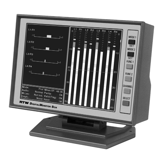
- Seite 43 Stereo-Kanalpaar L1:R1 Stereo-Kanalpaar L2:R2 Stereo-Kanalpaar L3:R3 Stereo-Kanalpaar L4:R4 Bild D 4-5: Der Multi-Corellator im „Multi Instrument 1“ im „4 x Stereo“-Modus...
- Seite 44 Bild D 4-6: Menü „Multi-Correlator“ mit Multi-Correlator-Parametern...
- Seite 46 Gewählter Eingangskanal Kanalstatus-Anzeige (Hardware-Status, Binär-An- zeige und Audio-Datenbits wählbar) Bild D 4-7: Die Kanal-Statusanzeige („Channel-Status“) im „Multi Instrument 1“...
- Seite 48 Bild D 4-8: Die AES-Status-Anzeige im „Multi Instrument 2“...
- Seite 49 Bild D 4-9: Die Stoppuhr im „Multi Instrument 2“...
- Seite 51 D 5. Menü Bild D 5-1: Das Hauptmenü des DigitalMonitor 8ch 10689...
- Seite 52 : s i Ä ö ä ä ä ä t a l t a l t a l t a l • • • • • • • • r ü i t l • • • •...
- Seite 53 Bild D 5-2: Das Menü „Modify Preset“ des DigitalMonitor 8ch 10689 ...
- Seite 54 Bild D 5-3: Das Untermenü „PPM-Digital“...
- Seite 56 Bild D 5-4: Das Untermenü „Routing, Label, Color“ im „4 x Stereo“-Modus...
- Seite 58 Fig. E 5-5: Das Ungtermenü „Digital-Errors“...
- Seite 59 P " " n r ü i t l : t r ä ä ä ä t a l t a l t a l t a l • • • • • • • • : t r –...
- Seite 60 ...
- Seite 61 Bild D 5-6: Das Untermenü „more ..“ für „Primary Function: Vectorscope“...
- Seite 62 Bild D 5-7: Das Untermenü „more ..“ für „Primary Function: MultiCorrelator“...
- Seite 63 Bild D 5-8: Das Untermenü „Toggle Selection“ für „Multi Instrument 1“...
- Seite 64 ...
- Seite 65 Bild D 5-9: Das Untermenü „Remote“ des DigitalMonitor 8ch 10689...
- Seite 66 General Bild D 5-10: Das Untermenü „General“ des DigitalMonitor 8ch 10689...
- Seite 69 D 6. Installation...
- Seite 70 Bild D 6-1: Anschlussfeld auf der Geräterückseite...
- Seite 71 P i n 1 P i n 1 4 P i n 2 P i n 1 5 P i n 3 P i n 1 6 P i n 4 P i n 1 7 P i n 5 P i n 1 8 P i n 6 P i n 1 9...
- Seite 72 P i n 6 P i n 1 P i n 1 1 P i n 7 P i n 2 P i n 1 2 P i n 8 P i n 1 3 P i n 3 P i n 9 P i n 1 4 P i n 4 P i n 1 0...
- Seite 73 Ω Ω Ω Ω Ω Ω Bild D 6-2: Teilansicht der Hauptplatine mit DIP-Schalter...
- Seite 75 D 7. Service...
- Seite 76 Bild D 7-1: Entfernen des Tischfußes (10689-PLUS) Bild D 7-2: Entfernen des rückwärtigen Abdeckblechs...
- Seite 77 Bild D 7-3: Lösen des Flachband-Anschlusskabels...
- Seite 78 Schraube in der Mitte nur bei 10689 Bild D 7-4: Lösen und Entnehmen von Anschlusswinkel und Hauptplatine Bild D 7-5: Entfernen des Flachband-Anschlusskabels von der Displayplatine...
- Seite 79 Bild D 7-6: Herauslösen der Display-Einheit...
- Seite 80 Bild D 7-7: Einsetzen und Befestigen der neuen Display-Einheit...
- Seite 81 Bild D 7-8: Einsetzen und Befestigen der neuen Skala Bild D 7-9: Aufstecken des Flachband-Anschlusskabels auf die Displayplatine...
- Seite 82 Schraube in der Mitte nur bei 10689 Bild D 7-10: Einsetzen und Befestigen der Hauptplatine und des Anschlusswinkels...
- Seite 83 Bild D 7-11: Aufstecken des Flachband-Anschlusskabels auf die Hauptplatine Bild D 7-12: Einsetzen und Befestigen des rückwärtigen Abdeckblechs...
- Seite 84 Bild D 7-13: Befestigen des Tischfußes (10689-PLUS)
- Seite 85 D 8. Zeichnungen...
- Seite 86 90 - 264 V AC/24 DC, 630 mA • passendes Netzanschlusskabel • Eurostecker • Kleinspannungsstecker 4-pol. • Kleinspannungsstecker 4-pol. DigitalMonitor 8ch 10689 Einbaukit 13713 für den Frontplatteneinbau Adapterrahmen 13711, 200 x 190 mm • Erforderlicher Frontplattenausschnitt: • zum Einbau von SurroundMonitoren...
-
Seite 91: Anhang A: Technische Daten
Anhang A: Technische Daten Ω... -
Seite 95: Anhang B: Ce-Konformitätserklärung
RTW GmbH & Co. KG Elbeallee 19 · 50765 Köln · Germany erklären in alleiniger Verantwortung, dass das Produkt: RTW DigitalMonitor 8ch der Serie 106nn einschl. aller Optionen auf das sich diese Erklärung bezieht, mit den folgenden Normen bzw. normativen Dokumenten übereinstimmt:... -
Seite 97: Anhang C: Index
Anhang C: Index... - Seite 99 Operating Manual english...
- Seite 101 E 1 Before you begin Fig. E 1-1: DigitalMonitor 8ch 10689 (left) and DigitalMonitor 8ch 10689-PLUS (right)
- Seite 102 ...
- Seite 107 PPM Section: graphical display modes and Peak Program Meter, loudness AES status data indicator, SPL spots Multi Instrument 1 PPM Section Multi Instrument 2 Multi Instrument 2: text-based information display Fig. E 2-1: The display elements of the DigitalMonitor 8ch 10689...
- Seite 108 Fig. E 2-2: The PPM section of the display highlighted with a white frame...
- Seite 109 Fig. E 2-3: The Multi Instrument 1 highlighted with a white frame showing the Vectorscope (Lissajous) in 4 x Stereo mode...
- Seite 110 Fig. E 2-4: The Multi Instrument 1 highlighted with a white frame showing the Multi Correlator in 4 x Stereo mode...
- Seite 111 Fig. E 2-5: The Multi Instrument 1 highlighted with a white frame showing the Channel Status in 4 x Stereo mode...
- Seite 112 Fig. E 2-6: The Multi Instrument 2 highlighted with a white frame showing the AES Status in 4 x Stereo mode...
- Seite 113 Fig. E 2-7: The Multi Instrument 2 highlighted with a white frame showing the Stopwatch in 4 x Stereo mode...
- Seite 115 E 3 Quick Start Multi Instrument 1: White frame shows Functions MODE buttons MODE cycles through all currently selected of selected available instruments instrument instrument Green spot Fig. E 3-1: The display of the DigitalMonitor 8ch 10689...
- Seite 117 Fig. E 3-2: The main menu of the DigitalMonitor 8ch 10689...
- Seite 121 Fig. E 3-3: The Save Preset screen of the DigitalMonitor 8ch 10689...
- Seite 122 e i f ! x i t a l t a l t a l t a l • • • • • • • • i t l • • • • – – – – i t l t a l •...
- Seite 123 Fig. E 3-4: The General menu of the DigitalMonitor 8ch 10689...
- Seite 124 Fig. E 3-5: The Toggle selection menu of the DigitalMonitor 8ch 10689...
- Seite 125 E 4 Display Modes The order of the channels Multi-standard peakmeters is adjusted automatically for digital signals according to the selected format or selected preset Peak hold indicator Combined display of peak Depending on the operating value, loudness and SPL for mode level display for SPL each channel is available.
- Seite 126 Fig. E 4-2: PPM Digital menu display with PPM parameters...
- Seite 128 The signal vectors of the Lissajous figure have their common source in the center of the graph 2-channel audio vectorscope for real time display of the stereo signal (Lissajous figures) Phase meter for selected channel pair Fig. E 4-3: The stereo vectorscope display in Multi Instrument 1 section...
- Seite 129 Fig. E 4-4: Vectorscope menu display with Vectorscope parameters...
- Seite 131 Stereo channel pair L1:R1 Stereo channel pair L2:R2 Stereo channel pair L3:R3 Stereo channel pair L4:R4 Fig. E 4-5: The Multi Corellator display in Multi Instrument 1 section...
- Seite 132 Fig. E 4-6: Multi Correlator menu display with Multi Correlator parameters...
- Seite 134 Selected input channel Channel status display (the display of hardware status, binary and audio data bits can be selected) Fig. E 4-7: The Channel Status display in Multi Instrument 1 section...
- Seite 136 Fig. E 4-8: The AES Status display in Multi Instrument 2 section...
- Seite 137 Fig. E 4-9: The Stopwatch display in Multi Instrument 2 section...
- Seite 139 E 5 Menu Fig. E 5-1: The Main menu of the DigitalMonitor 8ch 10689...
- Seite 140 e i f ! x i t a l t a l t a l t a l • • • • • • • • i t l • • • • – – – – i t l t a l •...
- Seite 141 Fig. E 5-2: The Modify Preset menu of the DigitalMonitor 8ch 10689 ...
- Seite 142 Fig. E 5-3: The PPM-Digital submenu...
- Seite 144 Fig. E 5-4: The Routing, Label, Color submenu in 4 x Stereo mode...
- Seite 146 Fig. E 5-5: The Digital-Errors submenu...
- Seite 147 i t l t a l t a l t a l t a l • • • • • • • • – – – – i t l t a l – – – – i t c i t c •...
- Seite 148 ...
- Seite 149 Fig. E 5-6: The more .. submenu for Primary Function: Vectorscope...
- Seite 150 Fig. E 5-7: The more .. submenu for Primary Function: MultiCorrelator...
- Seite 151 Fig. E 5-8: The Toggle Selection submenu for Multi Instrument 1...
- Seite 152 ...
- Seite 153 Fig. E 5-9: The Remote submenu of the DigitalMonitor 8ch 10689...
- Seite 154 Fig. E 5-10: The General submenu of the DigitalMonitor 8ch 10689...
- Seite 157 E 6 Installation...
- Seite 158 Fig. E 6-1: Connector panel on the rear side of the units...
- Seite 159 P i n 1 P i n 1 4 P i n 2 P i n 1 5 P i n 3 P i n 1 6 P i n 4 P i n 1 7 P i n 5 P i n 1 8 P i n 6 P i n 1 9...
- Seite 160 P i n 6 P i n 1 P i n 1 1 P i n 7 P i n 1 2 P i n 2 P i n 8 P i n 3 P i n 1 3 P i n 9 P i n 4 P i n 1 4 P i n 1 0...
- Seite 161 Ω Ω Fig. E 6-2: Partitial view of the main pcb with the DIP switch...
- Seite 163 E 7 Service...
- Seite 164 Fig. E 7-1: Removing the table stand (10689-PLUS) Fig. E 7-2: Removing of the backplane cover...
- Seite 165 Fig. E 7-3: Loosen the connecting cable...
- Seite 166 Screw in the middle with 10689 only Fig. E 7-4: Unscrew and removal of connector panel and main pcb Fig. E 7-5: Removal of the connecting flat cable from the display pcb...
- Seite 167 Fig. E 7-6: Removing the mounting unit with the display...
- Seite 168 Fig. E 7-7: Placing and fastening the new mounting unit...
- Seite 169 Fig. E 7-8: Placing and fastening the new scale Fig. E 7-9: Attaching the connecting flat cable...
- Seite 170 Screw in the middle with 10689 only Fig. E 7-10: Remounting the main pcb and the connector panel...
- Seite 171 Fig. E 7-11: Fastening the connecting flat cable to the main pcb Fig. E 7-12: Mounting the backplane cover...
- Seite 172 Fig. E 7-13: Fastening the table stand (10689-PLUS)
- Seite 173 E 8. Drawings...
- Seite 174 • corresponding power cable • Euro plug • locking 4-pin low voltage connector • Locking 4-pin low voltage connector DigitalMonitor 8ch 10689 Panel mounting kit 13713 for front panel installation Adapter frame 13711, 200 x 190 mm • Panel cut out: •...
- Seite 179 Appendix A: Specifications Ω...
- Seite 183 Co. KG Elbeallee 19 · 50765 Köln · Germany declare under sole responsibility that the product: RTW DigitalMonitor 8ch of the 106nn series incl. all options meets the intend of the Directive 89/336/EEC and Directive 73/23/ECC. Compliance was demonstrated to the following specifications as listed in the official journal of the European...
- Seite 185 Appendix C: Index...