Inhaltsverzeichnis
Werbung
Verfügbare Sprachen
Verfügbare Sprachen
Werbung
Inhaltsverzeichnis

Verwandte Anleitungen für Franke FQD 907


Inhaltszusammenfassung für Franke FQD 907
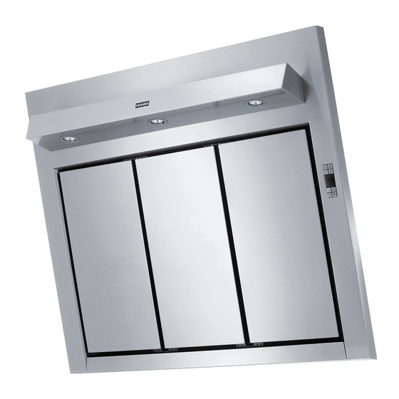
- Seite 1 Istruzioni per l’uso e l’installazione Cappa Instructions for use and installation Cooker Hood Mode d’emploi et installation Hotte de Cuisine Bedienungsanleitung und Einrichtung Dunstabzugshaube Kullanım ve montaj talimatları Davlumbaz FQD 907...
-
Seite 2: Inhaltsverzeichnis
Libretto di Istruzioni INDICE CONSIGLI E SUGGERIMENTI ..............................7 CARATTERISTICHE ................................8 INSTALLAZIONE..................................9 USO ......................................12 MANUTENZIONE .................................13... - Seite 3 Instructions Manual INDEX RECOMMENDATIONS AND SUGGESTIONS ........................16 CHARACTERISTICS................................17 INSTALLATION ..................................18 USE.......................................21 MAINTENANCE..................................22...
- Seite 4 Manuel d’Instructions SOMMAIRE CONSEILS ET SUGGESTIONS ............................25 CARACTERISTIQUES .................................26 INSTALLATION ..................................27 UTILISATION..................................30 ENTRETIEN..................................31...
- Seite 5 Bedienungsanleitung INHALTSVERZEICHNIS EMPFEHLUNGEN UND HINWEISE............................34 CHARAKTERISTIKEN................................35 MONTAGE....................................36 BEDIENUNG..................................39 WARTUNG....................................40...
- Seite 6 Kullanim Kilavuku IÇERIKLER TAVSIYELER VE ÖNERILER ..............................43 ÖZELLIKLER ..................................44 MONTAJ ....................................45 KULLANIM ....................................48 BAKIM....................................49...
-
Seite 7: Consigli E Suggerimenti
CONSIGLI E SUGGERIMENTI INSTALLAZIONE • Il produttore declina qualsiasi responsabilità per danni dovuti ad in- stallazione non corretta o non conforme alle regole dell’arte. • Verificare che la tensione di rete corrisponda a quella riportata nella targhetta posta all’interno della Cappa. •... -
Seite 8: Caratteristiche
CARATTERISTICHE Ingombro 7.2.1 Componenti Rif. Q.tà Componenti di Prodotto Corpo Cappa completo di: Comandi, Luce, Gruppo Ventilatore, Filtri Camino Superiore Camino Inferiore Griglia direzionata Uscita Aria Flangia Angolare Coperchio filtrante Rif. Q.tà Componenti di Installazione 7.2.1 Staffe Fissaggio Camino Superiore Tasselli Tasselli SB 12/10 Viti 4,2 x 44,4... -
Seite 9: Installazione
INSTALLAZIONE Foratura Parete e Fissaggio Staffe 7.2.1 200 200 180 180 Tracciare sulla Parete: • una linea Verticale fino al soffitto o al limite superiore, al centro della zona prevista per il montaggio della Cappa; • una linea Orizzontale a 960 mm min. sopra il Piano di Cottura. •... - Seite 10 Montaggio Corpo Cappa • Aprire i pannelli aspiranti. • Sganciare il pannello dal corpo cappa facendo scorre- re l’apposita leva del perno di fissaggio.(A) • Togliere i Filtri Antigrasso agendo sulle apposite maniglie. • Regolare le due viti Vr, delle staffe 11a, ad inizio corsa.(B) •...
-
Seite 11: Connessione Elettrica
Montaggio Camino Il camino può essere installato solo con la cappa colle- gata in versione aspirante. • Fissare l’angolare 15 al corpo cappa con le viti 12d (2,9 x 9,5) in dotazione. 7.2.1 Camino superiore • Allargare leggermente le due falde laterali, aggan- ciarle dietro le Staffe 7.2.1 e richiuderle fino a battu- •... -
Seite 12: Uso
Quadro comandi Tasto Funzione Display Accende e spegne il motore di aspirazione Visualizza la velocità impostata all’ultima velocità utilizzata. Decrementa la velocità di esercizio. Incrementa la velocità di esercizio. Attiva la velocità intensiva da qualsiasi velo- Visualizza HI e il punto in basso a destra lam- cità... -
Seite 13: Manutenzione
MANUTENZIONE TELECOMANDO (OPZIONALE) Questo apparecchio può essere comandato per mezzo di un tele- comando, alimentato con pile alcaline zinco-carbone da 1,5 V del tipo standard LR03-AAA. • Non riporre il telecomando in prossimità di fonti di calore. • Non disperdere le pile nell’ambiente, depositarle negli appositi contenitori. - Seite 14 Pannelli Aspiranti • Aprire i pannelli aspiranti. • Sganciare i pannelli laterali dal corpo cappa facendo scorrere l’apposita leva del perno di fissaggio. • Sganciare il pannello Centrale tirandolo energicamente, con entrambe le mani. • Pulire esternamente con un panno umido e detersivo liquido neutro.
-
Seite 15: Sostituzione Lampade
Illuminazione SOSTITUZIONE LAMPADE Lampade alogene da 20 W. • Togliere le due viti che fissano il Supporto illuminazione e sfi- larlo dalla Cappa. • Estrarre la Lampada dal Supporto. • Sostituirla con una nuova di uguali caratteristiche, facendo at- tenzione di inserire correttamente i due spinotti nella sede del Supporto. -
Seite 16: Recommendations And Suggestions
RECOMMENDATIONS AND SUGGESTIONS INSTALLATION • The manufacturer will not be held liable for any damages resulting from incorrect or improper installation. • Check that the mains voltage corresponds to that indicated on the rating plate fixed to the inside of the hood. •... -
Seite 17: Characteristics
CHARACTERISTICS Dimensions 7.2.1 Components Ref. Q.ty Product Components Hood Body, complete with: Controls, Light, Blower, Filters Upper Section Lower Section Directional Air Outlet grille Flange Angle iron Filter cover Ref. Q.ty Installation Components 7.2.1 Upper Chimney Section Fixing Brackets Wall Plugs Wall Plugs SB 12/10 Screws 4,2 x 44,4 Screws 2,9 x 6,5... -
Seite 18: Installation
INSTALLATION Wall drilling and bracket fixing 7.2.1 200 200 180 180 On the wall, draw • a Vertical line up to the ceiling or upper limit, at the centre of the area in which the Hood is to be fitted; •... - Seite 19 Mounting the hood body • Open the ducting panels. • Disconnect the panel from the hood canopy by slid- ing the fixing pin lever.(A) • Remove the metal grease filters by turning the han- dles provided. • Adjust the two screws Vr, on brackets 11a, to a mini- mum.(B) •...
-
Seite 20: Electrical Connection
Flue assembly The chimney can only be installed with exhausting hood • Fasten the angle iron 15 to the hood canopy using the screws 12d (2,9 x 9,5) provided. 7.2.1 Upper exhaust flue • Slightly widen the two sides of the upper flue and hook them behind the brackets 7.2.1, making sure that they are well seated. -
Seite 21: Use
Control board Function Display Switches the extractor motor on and off at the Indicates the selected speed. latest selected speed Decreases the suction speed. Increases the suction speed. By pressing this key it is possible to activate HI appears. The spot down on the right side the intensive speed from any previously se- flashes once a second. -
Seite 22: Maintenance
MAINTENANCE REMOTE CONTROL (OPTIONAL) The appliance can be controlled using a remote control powered by a 1.5 V carbon-zinc alkaline batteries of the standard LR03- AAA type. • Do not place the remote control near to heat sources. • Used batteries must be disposed of in the proper manner. Metal grease filters Filters can be washed in the dish machine. - Seite 23 Comfort panels • Open the comfort panels. • To unfasten the side panels from the hood casing it is necessa- ry to slide the fixing pivot lever. • When unfastening the central comfort panel pull it forcefully using both hands. •...
-
Seite 24: Light Replacement
Lighting LIGHT REPLACEMENT 20 W halogen light. • Remove the 2 screws fixing the Lighting support, and pull it out of from the Hood. • Extract the lamp from the Support. • Replace with another of the same type, making sure that the two pins are properly inserted in the lamp holder socket holes. -
Seite 25: Conseils Et Suggestions
CONSEILS ET SUGGESTIONS INSTALLATION • Le fabricant décline toute responsabilité en cas de dommage dû à une installation non correcte ou non conforme aux règles de l’art. • Vérifier que la tension du secteur correspond à la valeur qui figure sur la plaquette apposée à... - Seite 26 CARACTERISTIQUES Encombrement 7.2.1 Composants Réf. Q.té Composants de Produit Corps Hotte équipé de:Comandes, Lumière, Groupe Ventilateur, Filtres Cheminée Supérieure Cheminée Inférieure Grille orientée Sortie de l’Air Flasque Cornière Couvercle filtrant Réf. Q.té Composants pour l ’installation 7.2.1 Brides Fixation Cheminée Supérieure Chevilles Chevilles SB 12/10 Vis 4,2 x 44,4...
- Seite 27 INSTALLATION Perçage Paroi et Fixation Brides 7.2.1 200 200 180 180 Tracer sur la Paroi : • une ligne Verticale jusqu’au plafond ou à la limite supérieure, au centre de la zone prévue pour le montage de la Hotte ; •...
- Seite 28 Montage Corps Hotte • Ouvrir les panneaux aspirants. • Décrocher le panneau du corps de la hotte, en faisant coulisser le levier du goujon de fixation spécialement prévu.(A) • Enlever les filtres Anti-graisse, en intervenant sur les poignées spécialement prévues. •...
-
Seite 29: Branchement Electrique
Montage Cheminée La Cheminée peut être installée uniquement en version aspirante • Fixer la cornière 15 au corps de hotte avec le vis 12d (2,9 x 9,5) fournies. 7.2.1 Cheminée supérieure • Elargir légèrement les deux bords latériaux, et les accrocher derrières les brides 7.2.1 ;... - Seite 30 UTILISATION Tableau des commandes Touche Fonction Afficheur Allume et éteint le moteur d’aspiration à la Affiche la vitesse choisie dernière vitesse utilisée Diminue la vitesse de service Augmente la vitesse de service Active la vitesse intensive à partir de Affiche HI et le point en bas à droite clignote n’importe quelle vitesse, même du moteur une fois par seconde.
- Seite 31 ENTRETIEN TELECOMMANDE (FOURNIE SUR DEMANDE) Il est possible de commander cet appareil au moyen d’une télé- commande, alimentée avec des piles alcalines zinc-charbon 1,5 V du type standard LR03-AAA. • Ne pas ranger la télécommande à proximité de sources de cha- leur.
- Seite 32 Panneaux Aspirants • Ouvrir les panneaux aspirants. • Décrocher les panneaux latéraux du corps de la hotte en faisant coulisser le levier spécialement prévu du tourbillon de fixation. • Décrocher le panneau Central en le tirant énergiquement, des deux mains. •...
- Seite 33 Eclairage REMPLACEMENT LAMPES Lampe halogène de 20 W. • Retirer les 2 Vis qui fixent le Support éclairage et ôter ce der- nier de la Hotte. • Extraire la Lampe du Support. • Remplacer par une nouvelle lampe possédant les mêmes carac- téristiques, en veillant à...
-
Seite 34: Empfehlungen Und Hinweise
EMPFEHLUNGEN UND HINWEISE MONTAGE • Der Hersteller haftet nicht für Schäden, die auf eine fehlerhafte und unsachgemäße Montage zurückzuführen sind. • Prüfen, ob die Netzspannung mit dem Wert auf dem im Haubeninne- ren angebrachten Schild übereinstimmt. • Bei Geräten der Klasse I ist sicherzustellen, dass die elektrische An- lage des Wohnhauses über eine vorschriftsmäßige Erdung verfügt. - Seite 35 CHARAKTERISTIKEN Platzbedarf 7.2.1 Komponenten Pos. Produktkomponenten Haubenkörper mit Schaltern, Beleuchtung, Gebläse- gruppe, Filter oberer Kaminteil (option) unterer Kaminteil (option) Luftleitgitter Luftaustritt (option) Flansch (option) Winkel (option) Filterdeckel Pos. Montagekomponenten 7.2.1 Befestigungsbügel oberer Kaminteil (option) Dübel ( 4 option ) Dübel SB 12/10 Schrauben 4,2 x 44,4 ( 4 option ) Schrauben 2,9 x 6,5 ( 6 option ) Schrauben 2,9 x 9,5 ( 4 option )
- Seite 36 MONTAGE Bohren der Befestigungslöcher und Fixieren der Befestigungsbügel 7.2.1 200 200 180 180 An der Wand: • eine vertikale Linie bis zur Decke oder oberen Begrenzung zeichnen, und zwar in der Mitte des Bereiches, der zur Montage der Haube vorgesehen ist; •...
-
Seite 37: Anschluss In Abluftversion
Montage des Haubenkörpers • Die Filterpaneele öffnen. • Die Fettfilter mit den entsprechenden Griffen demon- tieren.(A) • Die Platte vom Haubenkörper aushaken, indem der Hebel des Befestigungsstiftes verschoben wird. • Die beiden Schrauben Vr der Bügel 11a so regulie- ren, dass sie nur bis zum Gewindebeginn einge- schraubt sind.(B) ( B ) •... -
Seite 38: Elektroanschluss
Kaminmontage Der Kamin Kann nur bei der Haube in der Abluftaus- führung angebracht werden. • Das Winkelstück 15 am Lüftereil mit 5 der Lieferung beigefügten Schrauben 12d (2,9x9,5) befestigen. 7.2.1 Oberer Kaminteil • Die beiden seitlichen Schenkel leicht auseinander- biegen, hinter den Bügeln 7.2.1 einhängen und bis zum Anschlag wieder schließen. -
Seite 39: Bedienung
BEDIENUNG Bedienblende Taste Funktion Display Schaltet den Motor der Absauganlage bei der Zeigt die eingestellte Geschwindigkeit an zuletzt verwendeten Geschwindigkeit ein und aus. Vermindert die Betriebsgeschwindigkeit. Erhöht die Betriebsgeschwindigkeit. Aktiviert von jeder Geschwindigkeit aus, auch Zeigt HI an und der Punkt unten rechts blinkt bei abgestelltem Motor, die Intensivgeschwin- einmal pro Sekunde. -
Seite 40: Wartung
WARTUNG FERNBEDIENUNG (OPTION) Dieses Gerät kann mit einer Fernbedienung gesteuert werden, welche mit alkalischen Zink-Kohle-Batterien 1,5 V des Standard- typs LR03-AAA versorgt wird. • Die Fernbedienung nicht in die Nähe von Hitzequellen legen. • Batterien müssen vorschriftsmäßig entsorgt werden. Metallfettfilter Die Fettfilter sind spülmaschinengeeignet und müssen gewaschen werden, sobald am Display die Aufschrift FF erscheint oder mindestens alle 2 Monate, oder auch öfter, je nach Intensität des... -
Seite 41: Auswechseln Des Aktivkohle-Geruchsfilters
Filterpaneele • Die Filterpaneele öffnen. • Den entsprechenden Hebel des Befestigungszapfens drehen und die Seitenpaneele vom Haubenkörper abhaken. • Das Mittelpaneel durch energisches Ziehen mit beiden Händen aushaken. • Die Außenseite mit einem feuchten Tuch und neutralem Flüs- sigreiniger säubern. •... -
Seite 42: Auswechseln Der Lampen
Beleuchtung AUSWECHSELN DER LAMPEN Halogenlampe 20 W • Die beiden Schrauben, die Lampenhalterung fixieren, lösen und die Halterung aus der Dunstabzugshaube ziehen. • Die Lampe aus der Halterung nehmen. • Die Lampe durch eine gleichwertige ersetzen und bei der Re- montage darauf achten, daß... -
Seite 43: Tavsiyeler Ve Öneriler
TAVSIYELER VE ÖNERILER MONTAJ • Yalnιş veya eksik montajdan doğan herhangi bir zararιn sorum- luluğu üreticiye ait değildir. • Besleme voltajιnιn, davlumbaz içerisine yerleştirilen bilgi etike- tinde belirtilenle aynι olup olmadιğιnι kontrol edin. • Sιnιf I elektrikli aletleri için, güç kaynağιnιn yeterli topraklamayι sağlayιp sağlamadιğιnι... - Seite 44 ÖZELLIKLER Boyutlar 7.2.1 Komponentler Ref. Miktar Ürün komponentleri Kumandaları, ışık, vantilatör grupları, filtreleri ile birlikte bir davlumbaz gövdesi Üst baca Alt baca İstikamet ayarlı hava çıkış ızgarası Flanş Dirsek Filtre kapak Rif. Miktar Montaj komponentleri 7.2.1 Üst baca tespit unsurları Dubel Dubel SB 12/10 Vida 4,2 x 44,4...
- Seite 45 MONTAJ Duvarın delinmesi ve kancaların vidalanması 7.2.1 200 200 180 180 Duvara şunları çizin: • Tavana veya üst sınıra kadar, Davlumbazın monte edilmesi öngörülen bölgenin merkezinde bir dikey çizgi çizin; • Pişirme hattının minimum 960 mm üzerinde yatay bir çizgi. •...
- Seite 46 Davlumbaz gövdesinin montajı • Emme panellerini açın. • Tespit ayağının ilgili kolunu sürerek paneli davlum- baz gövdesinden ayırın (A) • İlgili tespit unsurlarını açarak Yağ Filtrelerini çıkar- tın. • Yol başında 11a tespit unsurlarındaki iki adet Vr vi- dasını ayarlayın.(B) •...
-
Seite 47: Elektri̇k Bağlantisi
Baca Montajı Baca, sadece, davlumbaz emme versiyonunda bağlı i- ken monte edilebilir. • 15 dirseğini verilen 12d (2,9 x 9,5) vidaları ile dav- lumbaz gövdesine tespit edin. 7.2.1 Üst baca • Yan eteklerini hafifçe genişleterek 7.2.1 tespit unsur- larının arkasına takın ve pervaza yapışana kadar ka- patın. - Seite 48 KULLANIM Kumanda Tablosu Tuş Fonksiyon Gösterge Aspiratör motorunu, kullanılan en son hızda Ayarlanan hızı görüntüler. açıp kapatır. O an devrede olan hızı düşürür. O an devrede olan hızı arttırır. Motor kapalıyken bile herhangi bir hızdan yo- HI işaretini görüntüler ve sağ alttaki nokta sa- ğun hızı...
- Seite 49 BAKIM TELEKUMANDA (OPSİYONEL) Bu cihaza bir telekumanda ile de komut verilebilir; bu kumanda 1,5 Voltluk çinko-karbonlu LR03-AAA tipi standart alkalin pil- lerle çalışır. • Telekumandayı ısı kaynakları yakınında bırakmaynız. • Pilleri çevreye atmayınız, bunlara ayrılmış çöp toplama ka- plarına atınız. Madeni yağ...
- Seite 50 Emme panelleri • Emme panellerini açın. • Tespit ayağının ilgili kolunu çekerek yan panelleri davlumbaz gövdesinden çıkartın. • İki el ile kuvvetli bir şekilde çekerek orta paneli yerinden çı- kartın. • Dış taraftan nemli bir bez ve nötr sıvı deterjan ile temizleyin. •...
- Seite 51 Aydınlatma AMPUL DEĞİŞTİRME 20 W halojen ampuller • Lamba Destek parçasını sabitleyen iki vidayı söküp, parçayı Davlumbazdan çıkarınız. • Ampulü Destek parçasından çıkarınız. • Aynı özelliklere sahip yenisi ile değiştiriniz ve iki küçük (iğne) fişini Destek parçası içindeki yuvalarına takarken dikkat edi- niz.
- Seite 52 çevre ve insan sağlığı üzerindeki olumsuz etkilerini bertaraf etmeye katkı sağlamış olursunuz. Bu ürünün geri dönüşüm koşulları hakkında daha ayrıntılı bilgi için hudutları içinde bulunduğunuz belediyenin ilgili diaresine, atık yoketme servisine veya ürünün satıcısına danışınız. Franke S.p.a. Via Pignolini,2 37019 Peschiera del Garda (VR) www.franke.it...