Werbung
Quicklinks
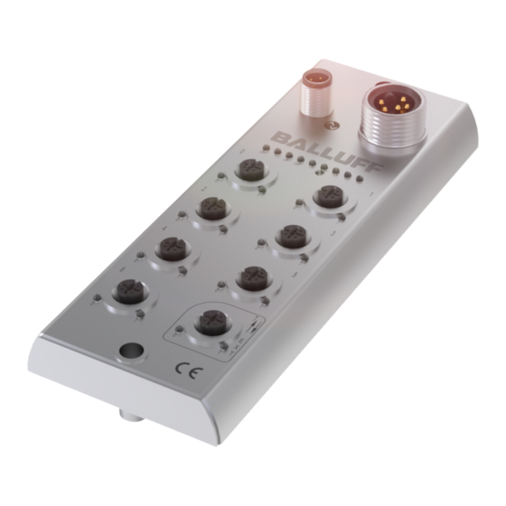
Balluff Network Interface IO-Link
Montageanleitung / Installation Guide
BNI IOL-302-002-E013
Diese Montageanleitung ersetzt nicht die Bedienungsanleitung. Für eine
ordnungsgemäße Installation und Betrieb lesen Sie bitte die
Bedienungsanleitung und die dazugehörigen Sicherheitshinweise
sorgfältig durch.
Diese finden Sie zum Download unter http://www.balluff.de.
Bitte wenden Sie sich bei weiteren Fragen an unseren Kundenservice.
This Installation Guide does not replace the User´s Guide. For proper
installation and operation, please read the User´s Guide and the asso-
ciated safety instructions carefully.
This is ready for you to download at http://www.balluff.com.
For any further question please contact our Customer Service.
Modulübersicht / Module overview
14
13
12
11
10
9
8
1
Befestigungsbohrung/
Mounting hole
2
Spannungsversorgung/
supply voltage connection
3
Status LED: Kommunikation/
Communication
4
Port 1
5
Port 3
6
Port 5
7
Port 7 Erweiterungsport/
Extension port
BNI IOL-302-002-E013
Mechanische Anbindung / Mechanical connections
Das Modul wird mit 2 Schrauben maximal M6 und 2 Unterlegscheiben
befestigt.
The module is attached using 2 M6 screws and 2 washers.
www.balluff.com
16 Ein- oder Ausgänge mit Erweiterungsport / 16 Inputs Outputs with extension port
1
2
3
4
5
6
7
1
8
Pin/Port LED: Signalstatus
9
Port 6
10 Port 4
11 Port 2
12 Port 0
13 Status LED: Modul Versor-
gung / Module supply
14 IO-Link Schnittstelle /
IO-Link interface
Port
0 - 7
IN / OUT
Elektrische Verbindungen / Electrical connection
Erdung / Grounding
Die Verbindung des FE-Anschlusses vom Gehäuse zur Maschine
muss niederohmig sein und erfolgt über die Befestigungs-
schraube.
The FE connection from the housing to the machine must be low-
impedance and and via mounting screw.
IO-Link Interface
M12 A-coded
Pin
Versorgungsspannung Controller +24V /
1
2
3
C/Q, IO-Link-Datenübertragungskanal /
4
C/Q, IO-Link data transmission channel
Nicht verwendete Buchsen müssen mit Blindkappen versehen
werden, damit die Schutzart IP 67 gewährleistet ist
Unused ports socket must be fitted with cover caps to ensure
IP67 protection rating.
Port
Pin
1
2
3
M12
4
A-coded
5
female
Die digitalen Eingänge entsprechen der Eingangskennlinie nach
EN 61131-2, Typ 3.
For the digital sensor inputs follow the input guideline per
EN61131-2, type 3.
Power IN
Funktion /
Pin
Function
IN
1
0 V
2
3
FE
7/8", male
4
+24 V
5
+24 V
Funktion / Function
Power supply controller+24V
n. c
GND, Bezugspotential /
GND, reference potential
Funktion / Function
IN / OUT
+24V
In /Out
0V
In / Out
FE
Beschreibung /
Description
GND Aktor- und Sensorversorgung /
GND actuator- and sensor power
supply
Funktionserde / Function earth
Modul- / Sensorversorgung /
Module / sensor power supply
Aktorversorgung /
Actuator power supply
1
Werbung

Verwandte Anleitungen für Balluff BNI IOL-302-002-E013


Inhaltszusammenfassung für Balluff BNI IOL-302-002-E013
- Seite 1 User´s Guide and the asso- ciated safety instructions carefully. This is ready for you to download at http://www.balluff.com. For any further question please contact our Customer Service. Die Verbindung des FE-Anschlusses vom Gehäuse zur Maschine muss niederohmig sein und erfolgt über die Befestigungs-...
- Seite 2 Balluff Network Interface IO-Link Funktionsanzeige / Function indicators Technische Daten / Technical data Dimension Pin- Port Module status Status Funktion / Function Grün / Versorgung Modul OK / Green Supply Module OK Versorgung Modul Unterspannung / Rot / Red Supply Module undervoltage Grün /...